1989 FORD FIESTA coolant level
[x] Cancel search: coolant levelPage 75 of 296
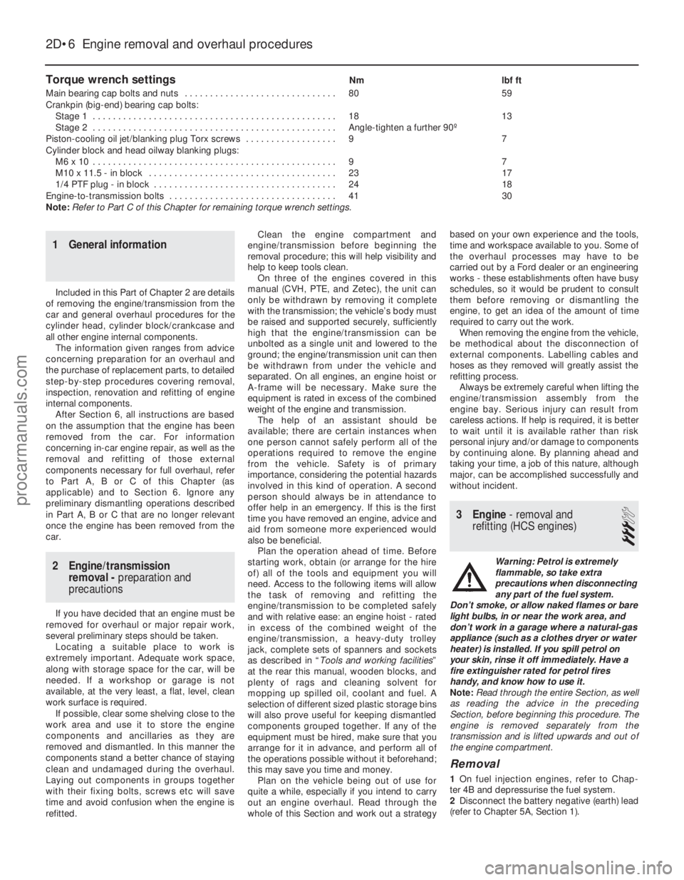
Torque wrench settingsNmlbf ft
Main bearing cap bolts and nuts . . . . . . . . . . . . . . . . . . . . . . . . . . . . . . 8059
Crankpin (big-end) bearing cap bolts: Stage 1 . . . . . . . . . . . . . . . . . . . . . . . . . . . . . . . . . . . .\
. . . . . . . . . . . . 1813
Stage 2 . . . . . . . . . . . . . . . . . . . . . . . . . . . . . . . . . . . .\
. . . . . . . . . . . . Angle-tighten a further 90º
Piston-cooling oil jet/blanking plug Torx screws . . . . . . . . . . . . . . . . . . 9 7
Cylinder block and head oilway blanking plugs:
M6 x 10 . . . . . . . . . . . . . . . . . . . . . . . . . . . . . . . . . . . .\
. . . . . . . . . . . . 9 7
M10 x 11.5 - in block . . . . . . . . . . . . . . . . . . . . . . . . . . . . . . . . . . . .\
. 2317
1/4 PTF plug - in block . . . . . . . . . . . . . . . . . . . . . . . . . . . . . . . . . . . .\
2418
Engine-to-transmission bolts . . . . . . . . . . . . . . . . . . . . . . . . . . . . . . . . . 4130
Note: Refer to Part C of this Chapter for remaining torque wrench settings.
2D•6 Engine removal and overhaul procedures
1595Ford Fiesta Remake
1 General information
Included in this Part of Chapter 2 are details
of removing the engine/transmission from the
car and general overhaul procedures for the
cylinder head, cylinder block/crankcase and
all other engine internal components.
The information given ranges from advice
concerning preparation for an overhaul and
the purchase of replacement parts, to detailed
step-by-step procedures covering removal,
inspection, renovation and refitting of engine
internal components.
After Section 6, all instructions are based
on the assumption that the engine has been
removed from the car. For information
concerning in-car engine repair, as well as the
removal and refitting of those external
components necessary for full overhaul, refer
to Part A, B or C of this Chapter (as
applicable) and to Section 6. Ignore any
preliminary dismantling operations described
in Part A, B or C that are no longer relevant
once the engine has been removed from the
car.
2 Engine/transmission removal - preparation and
precautions
If you have decided that an engine must be
removed for overhaul or major repair work,
several preliminary steps should be taken.
Locating a suitable place to work is
extremely important. Adequate work space,
along with storage space for the car, will be
needed. If a workshop or garage is not
available, at the very least, a flat, level, clean
work surface is required. If possible, clear some shelving close to the
work area and use it to store the engine
components and ancillaries as they are
removed and dismantled. In this manner the
components stand a better chance of staying
clean and undamaged during the overhaul.
Laying out components in groups together
with their fixing bolts, screws etc will save
time and avoid confusion when the engine is
refitted. Clean the engine compartment and
engine/transmission before beginning the
removal procedure; this will help visibility and
help to keep tools clean. On three of the engines covered in this
manual (CVH, PTE, and Zetec), the unit can
only be withdrawn by removing it complete
with the transmission; the vehicle’s body must
be raised and supported securely, sufficiently
high that the engine/transmission can be
unbolted as a single unit and lowered to the
ground; the engine/transmission unit can then
be withdrawn from under the vehicle and
separated. On all engines, an engine hoist or
A- frame will be necessary. Make sure the
equipment is rated in excess of the combined
weight of the engine and transmission. The help of an assistant should be
available; there are certain instances when
one person cannot safely perform all of the
operations required to remove the engine
from the vehicle. Safety is of primary
importance, considering the potential hazards
involved in this kind of operation. A second
person should always be in attendance to
offer help in an emergency. If this is the first
time you have removed an engine, advice and
aid from someone more experienced would
also be beneficial. Plan the operation ahead of time. Before
starting work, obtain (or arrange for the hire
of) all of the tools and equipment you will
need. Access to the following items will allow
the task of removing and refitting the
engine/transmission to be completed safely
and with relative ease: an engine hoist - rated
in excess of the combined weight of the
engine/transmission, a heavy-duty trolley
jack, complete sets of spanners and sockets
as described in “ Tools and working facilities ”
at the rear this manual, wooden blocks, and
plenty of rags and cleaning solvent for
mopping up spilled oil, coolant and fuel. A
selection of different sized plastic storage bins
will also prove useful for keeping dismantled
components grouped together. If any of the
equipment must be hired, make sure that you
arrange for it in advance, and perform all of
the operations possible without it beforehand;
this may save you time and money. Plan on the vehicle being out of use for
quite a while, especially if you intend to carry
out an engine overhaul. Read through the
whole of this Section and work out a strategy based on your own experience and the tools,
time and workspace available to you. Some of
the overhaul processes may have to be
carried out by a Ford dealer or an engineering
works - these establishments often have busy
schedules, so it would be prudent to consult
them before removing or dismantling the
engine, to get an idea of the amount of time
required to carry out the work.
When removing the engine from the vehicle,
be methodical about the disconnection of
external components. Labelling cables and
hoses as they removed will greatly assist the
refitting process.
Always be extremely careful when lifting the
engine/transmission assembly from the
engine bay. Serious injury can result from
careless actions. If help is required, it is better
to wait until it is available rather than risk
personal injury and/or damage to components
by continuing alone. By planning ahead and
taking your time, a job of this nature, although
major, can be accomplished successfully and
without incident.
3 Engine - removal and
refitting (HCS engines)
3
Warning: Petrol is extremely
flammable, so take extra
precautions when disconnecting
any part of the fuel system.
Don’t smoke, or allow naked flames or bare
light bulbs, in or near the work area, and
don’t work in a garage where a natural-gas
appliance (such as a clothes dryer or water
heater) is installed. If you spill petrol on
your skin, rinse it off immediately. Have a
fire extinguisher rated for petrol fires
handy, and know how to use it.
Note: Read through the entire Section, as well
as reading the advice in the preceding
Section, before beginning this procedure. The
engine is removed separately from the
transmission and is lifted upwards and out of
the engine compartment.
Removal
1 On fuel injection engines, refer to Chap-
ter 4B and depressurise the fuel system.
2 Disconnect the battery negative (earth) lead
(refer to Chapter 5A, Section 1).
procarmanuals.com
http://vnx.su
Page 77 of 296
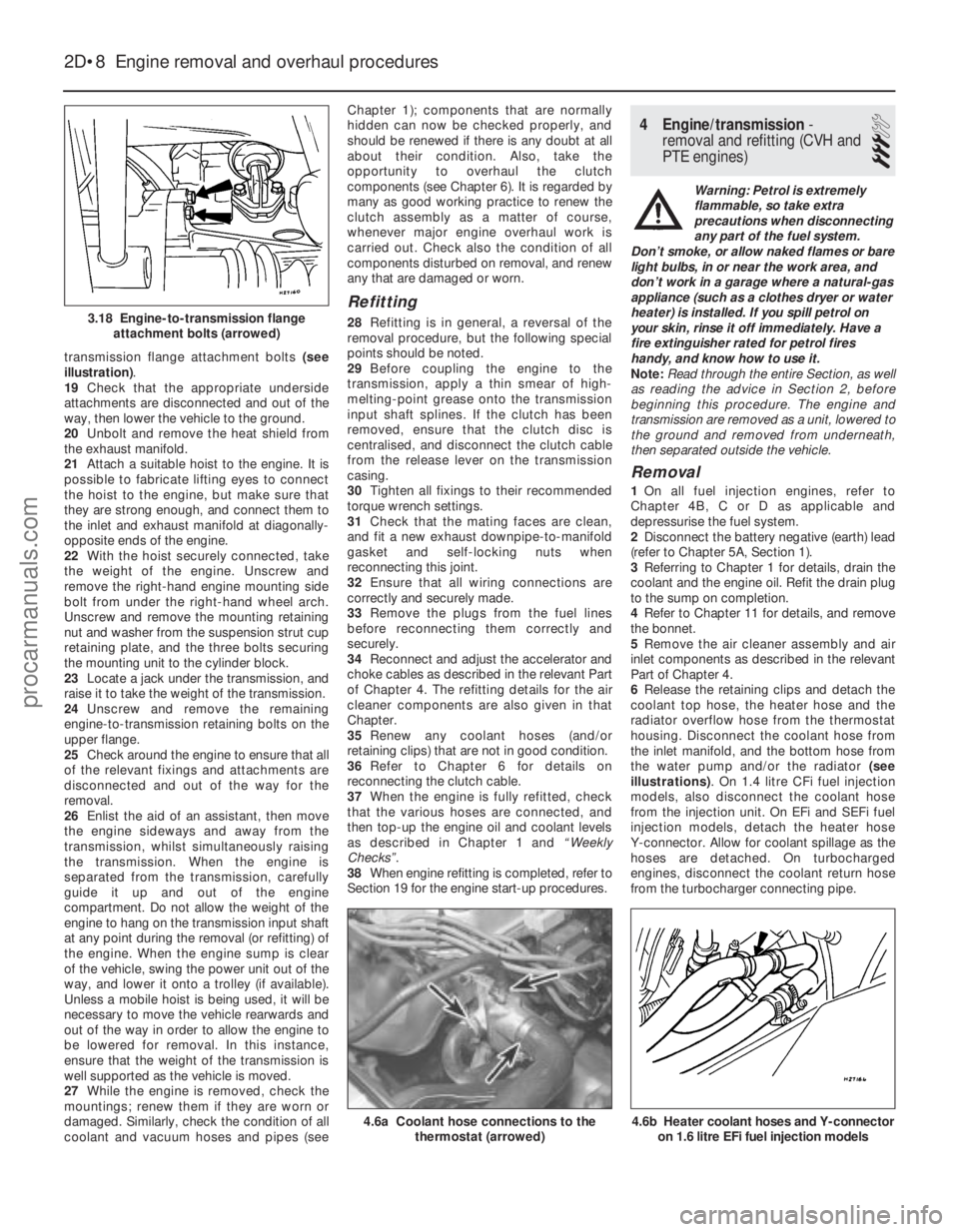
transmission flange attachment bolts (see
illustration) .
19 Check that the appropriate underside
attachments are disconnected and out of the
way, then lower the vehicle to the ground.
20 Unbolt and remove the heat shield from
the exhaust manifold.
21 Attach a suitable hoist to the engine. It is
possible to fabricate lifting eyes to connect
the hoist to the engine, but make sure that
they are strong enough, and connect them to
the inlet and exhaust manifold at diagonally-
opposite ends of the engine.
22 With the hoist securely connected, take
the weight of the engine. Unscrew and
remove the right-hand engine mounting side
bolt from under the right-hand wheel arch.
Unscrew and remove the mounting retaining
nut and washer from the suspension strut cup
retaining plate, and the three bolts securing
the mounting unit to the cylinder block.
23 Locate a jack under the transmission, and
raise it to take the weight of the transmission.
24 Unscrew and remove the remaining
engine-to-transmission retaining bolts on the
upper flange.
25 Check around the engine to ensure that all
of the relevant fixings and attachments are
disconnected and out of the way for the
removal.
26 Enlist the aid of an assistant, then move
the engine sideways and away from the
transmission, whilst simultaneously raising
the transmission. When the engine is
separated from the transmission, carefully
guide it up and out of the engine
compartment. Do not allow the weight of the
engine to hang on the transmission input shaft
at any point during the removal (or refitting) of
the engine. When the engine sump is clear
of the vehicle, swing the power unit out of the
way, and lower it onto a trolley (if available).
Unless a mobile hoist is being used, it will be
necessary to move the vehicle rearwards and
out of the way in order to allow the engine to
be lowered for removal. In this instance,
ensure that the weight of the transmission is
well supported as the vehicle is moved.
27 While the engine is removed, check the
mountings; renew them if they are worn or
damaged. Similarly, check the condition of all
coolant and vacuum hoses and pipes (see Chapter 1); components that are normally
hidden can now be checked properly, and
should be renewed if there is any doubt at all
about their condition. Also, take the
opportunity to overhaul the clutch
components (see Chapter 6). It is regarded by
many as good working practice to renew the
clutch assembly as a matter of course,
whenever major engine overhaul work is
carried out. Check also the condition of all
components disturbed on removal, and renew
any that are damaged or worn.
Refitting
28
Refitting is in general, a reversal of the
removal procedure, but the following special
points should be noted.
29 Before coupling the engine to the
transmission, apply a thin smear of high-
melting-point grease onto the transmission
input shaft splines. If the clutch has been
removed, ensure that the clutch disc is
centralised, and disconnect the clutch cable
from the release lever on the transmission
casing.
30 Tighten all fixings to their recommended
torque wrench settings.
31 Check that the mating faces are clean,
and fit a new exhaust downpipe-to-manifold
gasket and self-locking nuts when
reconnecting this joint.
32 Ensure that all wiring connections are
correctly and securely made.
33 Remove the plugs from the fuel lines
before reconnecting them correctly and
securely.
34 Reconnect and adjust the accelerator and
choke cables as described in the relevant Part
of Chapter 4. The refitting details for the air
cleaner components are also given in that
Chapter.
35 Renew any coolant hoses (and/or
retaining clips) that are not in good condition.
36 Refer to Chapter 6 for details on
reconnecting the clutch cable.
37 When the engine is fully refitted, check
that the various hoses are connected, and
then top-up the engine oil and coolant levels
as described in Chapter 1 and “Weekly
Checks”.
38 When engine refitting is completed, refer to
Section 19 for the engine start-up procedures.
4 Engine/transmission -
removal and refitting (CVH and
PTE engines)
3
Warning: Petrol is extremely
flammable, so take extra
precautions when disconnecting
any part of the fuel system.
Don’t smoke, or allow naked flames or bare
light bulbs, in or near the work area, and
don’t work in a garage where a natural-gas
appliance (such as a clothes dryer or water
heater) is installed. If you spill petrol on
your skin, rinse it off immediately. Have a
fire extinguisher rated for petrol fires
handy, and know how to use it.
Note: Read through the entire Section, as well
as reading the advice in Section 2, before
beginning this procedure. The engine and
transmission are removed as a unit, lowered to
the ground and removed from underneath,
then separated outside the vehicle.
Removal
1 On all fuel injection engines, refer to
Chapter 4B, C or D as applicable and
depressurise the fuel system.
2 Disconnect the battery negative (earth) lead
(refer to Chapter 5A, Section 1).
3 Referring to Chapter 1 for details, drain the
coolant and the engine oil. Refit the drain plug
to the sump on completion.
4 Refer to Chapter 11 for details, and remove
the bonnet.
5 Remove the air cleaner assembly and air
inlet components as described in the relevant
Part of Chapter 4.
6 Release the retaining clips and detach the
coolant top hose, the heater hose and the
radiator overflow hose from the thermostat
housing. Disconnect the coolant hose from
the inlet manifold, and the bottom hose from
the water pump and/or the radiator (see
illustrations) . On 1.4 litre CFi fuel injection
models, also disconnect the coolant hose
from the injection unit. On EFi and SEFi fuel
injection models, detach the heater hose
Y-connector. Allow for coolant spillage as the
hoses are detached. On turbocharged
engines, disconnect the coolant return hose
from the turbocharger connecting pipe.
2D•8 Engine removal and overhaul procedures
4.6b Heater coolant hoses and Y-connector on 1.6 litre EFi fuel injection models4.6a Coolant hose connections to the thermostat (arrowed)
3.18 Engine-to-transmission flangeattachment bolts (arrowed)
1595Ford Fiesta Remakeprocarmanuals.com
http://vnx.su
Page 79 of 296
25Unscrew the retaining bolt, and detach
the shift rod stabiliser from the transmission.
As it is detached, note the washer located
between the stabiliser and the transmission.
Tie the stabiliser and the shift rod up out of
the way.
Automatic transmission models
26 Unclip and detach the wiring connector
from the starter inhibitor switch (on the
transmission housing).
27 Referring to the relevant Part of Chapter 4
for details, unhook the accelerator (cam plate)
cable from the carburettor or fuel injection unit
(as applicable) at the transmission end of
the cable. Undo the retaining bolt and
detach the cable sheath bracket from the
transmission. Detach the cam plate cable
from the link.
28 Undo the two nuts from the selector cable
bracket which connects it to the lever on the
selector shaft. Disconnect the yoke from the
lever on the selector shaft and the cable from
the lever.
29 Unscrew the union nuts, and disconnect
the oil cooler feed and return pipes from the
transmission. Allow for a certain amount of
spillage, and plug the connections to prevent
the ingress of dirt.
All models
30 Unscrew the retaining nut and withdraw
the Torx-type clamp bolt securing the lower
suspension arm to the spindle carrier on each
side.
31 Refer to Chapter 10 for details, and
detach the right-hand and left-hand track rod
end balljoints from the spindle carriers.
32 On vehicles fitted with the anti-lock
braking system, refer to Chapter 9 and release
the right-hand modulator from its mounting
bracket without disconnecting the rigid brake
pipes or return hose. Tie the modulator
securely to the bulkhead. Additionally, undo
the three bolts securing the modulator
bracket.
33 Insert a suitable lever between the right-
hand driveshaft inner joint and the
transmission housing, and prise free the
driveshaft from the transmission; be prepared
for oil spillage from the transmission case
through the vacated driveshaft aperture. As it
is being prised free, simultaneously pull the
roadwheel outwards on that side, to enable
the driveshaft inboard end to separate
from the transmission. Once it is free,
suspend and support the driveshaft from the
steering gear, to prevent unnecessary strain
being placed on the driveshaft joints.
34 Insert a suitable plastic plug (or if
available, an old driveshaft joint), into the
transmission driveshaft aperture, to
immobilise the gears of the differential unit.
35 Proceed as described above in
paragraphs 33 and 34, and disconnect the
left-hand driveshaft from the transmission.
36 Connect a suitable lift hoist and sling to
the engine, connecting to the lifting eyes. When securely connected, take the weight of
the engine/transmission unit so that the
tension is relieved from the mountings.
37
Undo the retaining bolts and nuts and
detach the right-hand engine mounting from
the vehicle body.
38 Undo the four bolts securing the
transmission bearer to the underside of the
vehicle body. The transmission bearer is
removed with the engine/transmission
assembly.
39 Unscrew the three retaining bolts, and
remove the auxiliary drivebelt cover from
under the crankshaft pulley.
40 The engine/transmission unit should now
be ready for removal from the vehicle. Check
that all of the associated connections and
fittings are disconnected from the engine and
transmission, and positioned out of the way.
41 Enlist the aid of an assistant to help
steady and guide the power unit down
through the engine compartment as it is
removed. If available, position a suitable
engine trolley or crawler board under the
engine/transmission so that when lowered,
the power unit can be withdrawn from the
front end of the vehicle, and then moved to
the area where it is to be cleaned and
dismantled. On automatic transmission
models, particular care must be taken not to
damage the transmission fluid pan (sump)
during the removal and subsequent refitting
processes.
42 Carefully lower the engine and
transmission unit, ensuring that no fittings
become snagged. Detach the hoist and
remove the power unit from under the vehicle.
43 Referring to the relevant Part of Chapter 7,
separate the transmission from the engine.
44 While the engine/transmission is removed,
check the mountings; renew them if they are
worn or damaged. Similarly, check the
condition of all coolant and vacuum hoses
and pipes (see Chapter 1). Components that
are normally hidden can now be checked
properly, and should be renewed if there is
any doubt at all about their condition. Where
the vehicle is fitted with manual transmission,
take the opportunity to inspect the clutch
components (see Chapter 6). It is regarded by
many as good working practice to renew the
clutch assembly as a matter of course,
whenever major engine overhaul work is
carried out. Check also the condition of all
components (such as the transmission oil
seals) disturbed on removal, and renew any
that are damaged or worn.
Refitting
45 Refitting is a reversal of removal, however
note the following additional points:
a) Refer to the applicable Chapters and Sections as for removal.
b) Fit new spring clips to the grooves in the
inboard end of the right- and left-hand
driveshaft joints. Lubricate the splines
with transmission oil prior to fitting. c) Renew the exhaust flange gasket when
reconnecting the exhaust. Ensure that all
wires are routed clear of the exhaust
system and, on catalytic converter
models, ensure that the heat shields are
securely and correctly fitted.
d) Ensure that all earth lead connections are
clean and securely made.
e) Tighten all nuts and bolts to the specified torque.
f) Fit a new oil filter, and refill the engine and transmission with oil, with reference to
Chapter 1.
g) Refill the cooling system with reference to Chapter 1.
h) Refit the alternator and starter motor with reference to Chapter 5A.
i) Where applicable, refit the power steering pump with reference to Chapter 10.
46 When engine and transmission refitting is
complete, refer to the procedures described
in Section 19 before restarting the engine.
5 Engine/transmission -
removal and refitting
(Zetec engines)
3
Warning: Petrol is extremely
flammable, so take extra
precautions when disconnecting
any part of the fuel system.
Don’t smoke, or allow naked flames or
bare light bulbs, in or near the work area,
and don’t work in a garage where a
natural-gas appliance (such as a clothes
dryer or water heater) is installed. If you
spill petrol on your skin, rinse it off
immediately. Have a fire extinguisher rated
for petrol fires handy, and know how to
use it.
Note: Read through the entire Section, as well
as reading the advice in Section 2, before
beginning this procedure. The engine and
transmission are removed as a unit, lowered to
the ground and removed from underneath,
then separated outside the vehicle.
Removal
1 Park the vehicle on firm, level ground, apply
the handbrake firmly, and slacken the nuts
securing both front roadwheels.
2 Depressurise the fuel system as described
in Chapter 4D.
3 Disconnect the battery negative (earth) lead
(refer to Chapter 5A, Section 1).
4 Place protective covers on the wings, then
remove the bonnet (see Chapter 11).
5 Drain the cooling system and the engine oil
(see Chapter 1).
6 Remove the air inlet components and the
complete air cleaner assembly as described in
Chapter 4D.
7 Equalise the pressure in the fuel tank by
removing the filler cap, then release the fuel
feed and return quick-release couplings, and
pull the hoses off the fuel pipes. Plug or cap
all open fittings.
2D•10 Engine removal and overhaul procedures
1595Ford Fiesta Remakeprocarmanuals.com
http://vnx.su
Page 94 of 296
Plastigauge to the scale printed on the
Plastigauge envelope, to obtain the running
clearance (see illustration 17.15) . Compare it
to the Specifications, to make sure the
clearance is correct.
14 If the clearance is not as specified, seek
the advice of a Ford dealer or similar engine
reconditioning specialist - if the crankshaft
journals are in good condition it may be
possible simply to renew the shells to achieve
the correct clearance. If this is not possible,
the crankshaft must be reground by a
specialist, who can also supply the necessary
undersized shells. First though, make sure
that no dirt or oil was trapped between the
bearing shells and the connecting rod or cap
when the clearance was measured. Also,
recheck the crankpin diameter. If the
Plastigauge was wider at one end than the
other, the crankpin journal may be tapered.
15 Carefully scrape all traces of the
Plastigauge material off the journal and the
bearing surface. Be very careful not to scratch
the bearing - use your fingernail or the edge of a credit card.
Final piston/connecting rod
refitting
16 Make sure the bearing surfaces are
perfectly clean, then apply a uniform layer of
clean molybdenum disulphide-based grease,
engine assembly lubricant, or clean engine oil,
to both of them. You’ll have to push the piston
into the cylinder to expose the bearing surface
of the shell in the connecting rod.
17 Slide the connecting rod back into place
on the crankpin (big-end) journal, refit the big-
end bearing cap, and then tighten the bolts as
described above.
18 Repeat the entire procedure for the
remaining piston/connecting rod assemblies.
19 The important points to remember are:
a) Keep the backs of the bearing shells and the recesses of the connecting rods and
caps perfectly clean when assembling
them.
b) Make sure you have the correct
piston/rod assembly for each cylinder -
use the etched cylinder numbers to
identify the front-facing side of both the
rod and its cap.
c) The arrow on the piston crown must face the timing belt/chain end of the engine.
d) Lubricate the cylinder bores with clean
engine oil.
e) Lubricate the bearing surfaces when refitting the big-end bearing caps after the
running clearance has been checked. 20
After all the piston/connecting rod
assemblies have been properly installed,
rotate the crankshaft a number of times by
hand, to check for any obvious binding.
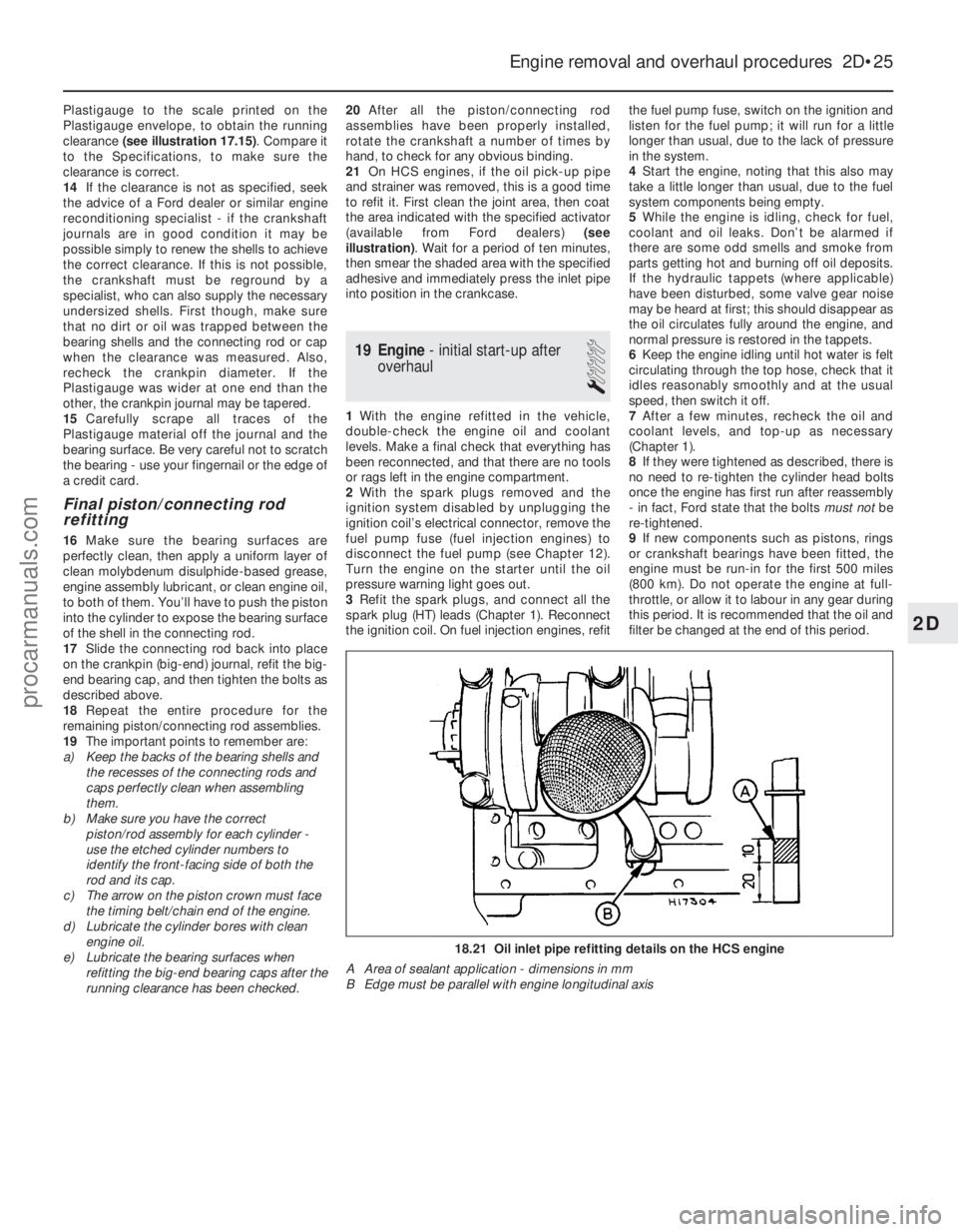
21 On HCS engines, if the oil pick-up pipe
and strainer was removed, this is a good time
to refit it. First clean the joint area, then coat
the area indicated with the specified activator
(available from Ford dealers) (see
illustration) . Wait for a period of ten minutes,
then smear the shaded area with the specified
adhesive and immediately press the inlet pipe
into position in the crankcase.
19 Engine - initial start-up after
overhaul
1
1 With the engine refitted in the vehicle,
double-check the engine oil and coolant
levels. Make a final check that everything has
been reconnected, and that there are no tools
or rags left in the engine compartment.
2 With the spark plugs removed and the
ignition system disabled by unplugging the
ignition coil’s electrical connector, remove the
fuel pump fuse (fuel injection engines) to
disconnect the fuel pump (see Chapter 12).
Turn the engine on the starter until the oil
pressure warning light goes out.
3 Refit the spark plugs, and connect all the
spark plug (HT) leads (Chapter 1). Reconnect
the ignition coil. On fuel injection engines, refit the fuel pump fuse, switch on the ignition and
listen for the fuel pump; it will run for a little
longer than usual, due to the lack of pressure
in the system.
4
Start the engine, noting that this also may
take a little longer than usual, due to the fuel
system components being empty.
5 While the engine is idling, check for fuel,
coolant and oil leaks. Don’t be alarmed if
there are some odd smells and smoke from
parts getting hot and burning off oil deposits.
If the hydraulic tappets (where applicable)
have been disturbed, some valve gear noise
may be heard at first; this should disappear as
the oil circulates fully around the engine, and
normal pressure is restored in the tappets.
6 Keep the engine idling until hot water is felt
circulating through the top hose, check that it
idles reasonably smoothly and at the usual
speed, then switch it off.
7 After a few minutes, recheck the oil and
coolant levels, and top-up as necessary
(Chapter 1).
8 If they were tightened as described, there is
no need to re-tighten the cylinder head bolts
once the engine has first run after reassembly
- in fact, Ford state that the bolts must notbe
re-tightened.
9 If new components such as pistons, rings
or crankshaft bearings have been fitted, the
engine must be run-in for the first 500 miles
(800 km). Do not operate the engine at full-
throttle, or allow it to labour in any gear during
this period. It is recommended that the oil and
filter be changed at the end of this period.
Engine removal and overhaul procedures 2D•25
18.21 Oil inlet pipe refitting details on the HCS engine
A Area of sealant application - dimensions in mm
B Edge must be parallel with engine longitudinal axis
2D
1595Ford Fiesta Remakeprocarmanuals.com
http://vnx.su
Page 96 of 296
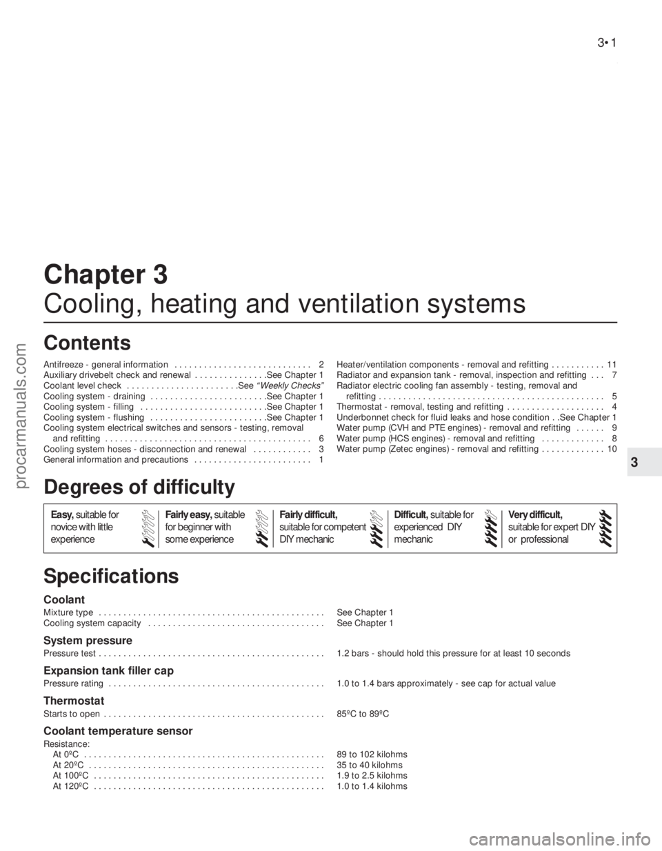
3
1595Ford Fiesta Remake
Coolant
Mixture type . . . . . . . . . . . . . . . . . . . . . . . . . . . . . . . . . . . .\
. . . . . . . . . . See Chapter 1
Cooling system capacity . . . . . . . . . . . . . . . . . . . . . . . . . . . . . . . . . . . .\
See Chapter 1
System pressure
Pressure test . . . . . . . . . . . . . . . . . . . . . . . . . . . . . . . . . . . .\
. . . . . . . . . . 1.2 bars - should hold this pressure for at least 10 seconds
Expansion tank filler cap
Pressure rating . . . . . . . . . . . . . . . . . . . . . . . . . . . . . . . . . . . .\
. . . . . . . . 1.0 to 1.4 bars approximately - see cap for actual value
Thermostat
Starts to open . . . . . . . . . . . . . . . . . . . . . . . . . . . . . . . . . . . .\
. . . . . . . . . 85ºC to 89ºC
Coolant temperature sensor
Resistance:At 0ºC . . . . . . . . . . . . . . . . . . . . . . . . . . . . . . . . . . . .\
. . . . . . . . . . . . . 89 to 102 kilohms
At 20ºC . . . . . . . . . . . . . . . . . . . . . . . . . . . . . . . . . . . .\
. . . . . . . . . . . . 35 to 40 kilohms
At 100ºC . . . . . . . . . . . . . . . . . . . . . . . . . . . . . . . . . . . .\
. . . . . . . . . . . 1.9 to 2.5 kilohms
At 120ºC . . . . . . . . . . . . . . . . . . . . . . . . . . . . . . . . . . . .\
. . . . . . . . . . . 1.0 to 1.4 kilohms
Chapter 3
Cooling, heating and ventilation systems
Antifreeze - general information . . . . . . . . . . . . . . . . . . . . . . . . . . . . 2
Auxiliary drivebelt check and renewal . . . . . . . . . . . . . . .See Chapter 1
Coolant level check . . . . . . . . . . . . . . . . . . . . . . .See
“Weekly Checks”
Cooling system - draining . . . . . . . . . . . . . . . . . . . . . . . .See Chapter 1
Cooling system - filling . . . . . . . . . . . . . . . . . . . . . . . . . .See Chapter 1
Cooling system - flushing . . . . . . . . . . . . . . . . . . . . . . . .See Chapter 1
Cooling system electrical switches and sensors - testing, removal and refitting . . . . . . . . . . . . . . . . . . . . . . . . . . . . . . . . . . . .\
. . . . . . 6
Cooling system hoses - disconnection and renewal . . . . . . . . . . . . 3
General information and precautions . . . . . . . . . . . . . . . . . . . . . . . . 1 Heater/ventilation components - removal and refitting . . . . . . . . . . . 11
Radiator and expansion tank - removal, inspection and refitting . . . 7
Radiator electric cooling fan assembly - testing, removal and
refitting . . . . . . . . . . . . . . . . . . . . . . . . . . . . . . . . . . . .\
. . . . . . . . . . 5
Thermostat - removal, testing and refitting . . . . . . . . . . . . . . . . . . . . 4
Underbonnet check for fluid leaks and hose condition . .See Chapter 1
Water pump (CVH and PTE engines) - removal and refitting . . . . . . 9
Water pump (HCS engines) - removal and refitting . . . . . . . . . . . . . 8
Water pump (Zetec engines) - removal and refitting . . . . . . . . . . . . . 10
3•1
Specifications Contents
Easy, suitable for
novice with little
experience Fairly easy,
suitable
for beginner with
some experience Fairly difficult,
suitable for competent
DIY mechanic
Difficult,
suitable for
experienced DIY
mechanic Very difficult,
suitable for expert DIY
or professional
Degrees of difficulty
54321
procarmanuals.com
http://vnx.su
Page 98 of 296
Before adding antifreeze, check all hoses
and hose connections, because antifreeze
tends to leak through very small openings.
Engines don’t normally consume coolant, so if
the level falls regularly, find the cause and
correct it. The exact mixture of antifreeze-to-water
which you should use depends on the relative
weather conditions. The mixture should
contain at least 40% antifreeze, but not more
than 70%. Consult the mixture ratio chart on
the antifreeze container before adding
coolant. Hydrometers are available at most
automotive accessory shops to test the
coolant. Use only good-quality ethylene-
glycol-based antifreeze which meets the
vehicle manufacturer’s specifications.
3 Cooling system hoses -
disconnection and renewal
1
Note: Refer to the warnings given in Section 1
of this Chapter before starting work.
1 If the checks described in Chapter 1 reveal
a faulty hose, it must be renewed as follows.
2 First drain the cooling system (see Chap-
ter 1); if the antifreeze is not due for renewal,
the drained coolant may be re-used, if it is
collected in a clean container.
3 To disconnect any hose, use a pair of pliers
to release the spring clamps (or a screwdriver
to slacken screw-type clamps), then move
them along the hose clear of the union.
Carefully work the hose off its stubs. The
hoses can be removed with relative ease
when new - on an older car, they may have
stuck.
4 If a hose proves stubborn, try to release it
by rotating it on its unions before attempting
to work it off. Gently prise the end of the hose
with a blunt instrument (such as a flat-bladed
screwdriver), but do not apply too much force,
and take care not to damage the pipe stubs or
hoses. Note in particular that the radiator hose
unions are fragile; do not use excessive force
when attempting to remove the hoses.
5 When refitting a hose, first slide the clamps
onto the hose, then work the hose onto its
unions. 6
Work each hose end fully onto its union,
then check that the hose is settled correctly
and is properly routed. Slide each clip along
the hose until it is behind the union flared end,
before tightening it securely.
7 Refill the system with coolant (see Chap-
ter 1).
8 Check carefully for leaks as soon as
possible after disturbing any part of the
cooling system.
4 Thermostat -
removal, testing and refitting
1
Note: Refer to the warnings given in Section 1
of this Chapter before starting work.
Removal
1 Disconnect the battery negative (earth) lead
(refer to Chapter 5A, Section 1).
2 Drain the cooling system (see Chapter 1).
3 Refer to the relevant Part of Chapter 4 and
remove the air cleaner or air inlet hoses,
according to engine type as necessary, to
gain access to the thermostat housing.
HCS, CVH and PTE engines
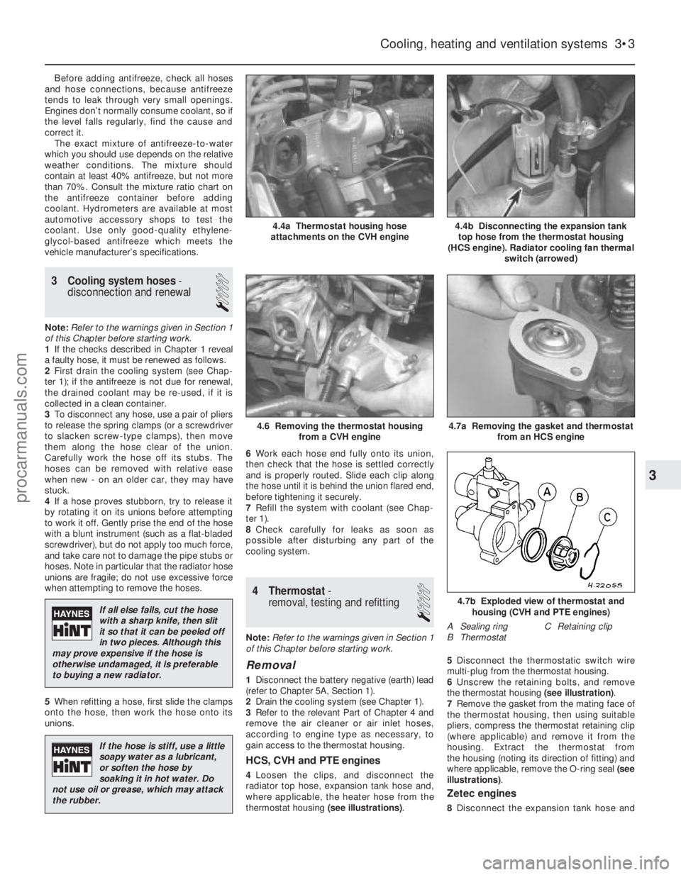
4 Loosen the clips, and disconnect the
radiator top hose, expansion tank hose and,
where applicable, the heater hose from the
thermostat housing (see illustrations).5
Disconnect the thermostatic switch wire
multi-plug from the thermostat housing.
6 Unscrew the retaining bolts, and remove
the thermostat housing (see illustration).
7 Remove the gasket from the mating face of
the thermostat housing, then using suitable
pliers, compress the thermostat retaining clip
(where applicable) and remove it from the
housing. Extract the thermostat from
the housing (noting its direction of fitting) and
where applicable, remove the O-ring seal (see
illustrations) .
Zetec engines
8Disconnect the expansion tank hose and
Cooling, heating and ventilation systems 3•3
4.4b Disconnecting the expansion tank
top hose from the thermostat housing
(HCS engine). Radiator cooling fan thermal switch (arrowed)4.4a Thermostat housing hose
attachments on the CVH engine
4.7b Exploded view of thermostat and housing (CVH and PTE engines)
A Sealing ring C Retaining clip
B Thermostat
4.7a Removing the gasket and thermostat from an HCS engine4.6 Removing the thermostat housingfrom a CVH engine
3
1595Ford Fiesta Remake
If all else fails, cut the hose
with a sharp knife, then slit
it so that it can be peeled off
in two pieces. Although this
may prove expensive if the hose is
otherwise undamaged, it is preferable
to buying a new radiator.
If the hose is stiff, use a little
soapy water as a lubricant,
or soften the hose by
soaking it in hot water. Do
not use oil or grease, which may attack
the rubber.
procarmanuals.com
http://vnx.su
Page 99 of 296
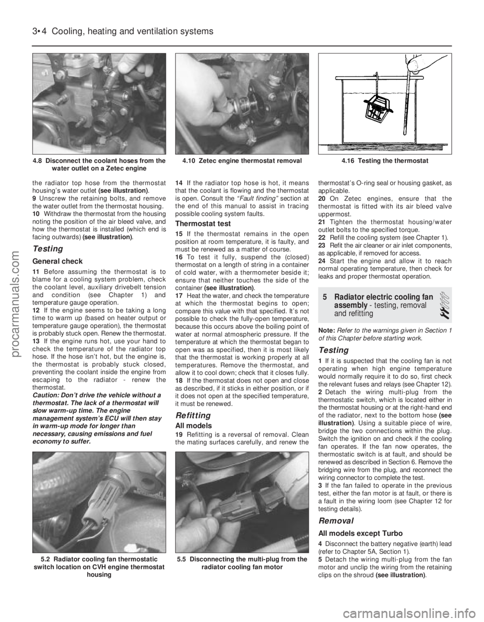
the radiator top hose from the thermostat
housing’s water outlet (see illustration).
9 Unscrew the retaining bolts, and remove
the water outlet from the thermostat housing.
10 Withdraw the thermostat from the housing
noting the position of the air bleed valve, and
how the thermostat is installed (which end is
facing outwards) (see illustration).
Testing
General check
11Before assuming the thermostat is to
blame for a cooling system problem, check
the coolant level, auxiliary drivebelt tension
and condition (see Chapter 1) and
temperature gauge operation.
12 If the engine seems to be taking a long
time to warm up (based on heater output or
temperature gauge operation), the thermostat
is probably stuck open. Renew the thermostat.
13 If the engine runs hot, use your hand to
check the temperature of the radiator top
hose. If the hose isn’t hot, but the engine is,
the thermostat is probably stuck closed,
preventing the coolant inside the engine from
escaping to the radiator - renew the
thermostat.
Caution: Don’t drive the vehicle without a
thermostat. The lack of a thermostat will
slow warm-up time. The engine
management system’s ECU will then stay
in warm-up mode for longer than
necessary, causing emissions and fuel
economy to suffer. 14
If the radiator top hose is hot, it means
that the coolant is flowing and the thermostat
is open. Consult the “Fault finding” section at
the end of this manual to assist in tracing
possible cooling system faults.
Thermostat test
15 If the thermostat remains in the open
position at room temperature, it is faulty, and
must be renewed as a matter of course.
16 To test it fully, suspend the (closed)
thermostat on a length of string in a container
of cold water, with a thermometer beside it;
ensure that neither touches the side of the
container (see illustration) .
17 Heat the water, and check the temperature
at which the thermostat begins to open;
compare this value with that specified. It’s not
possible to check the fully-open temperature,
because this occurs above the boiling point of
water at normal atmospheric pressure. If the
temperature at which the thermostat began to
open was as specified, then it is most likely
that the thermostat is working properly at all
temperatures. Remove the thermostat, and
allow it to cool down; check that it closes fully.
18 If the thermostat does not open and close
as described, if it sticks in either position, or if
it does not open at the specified temperature,
it must be renewed.
Refitting
All models
19 Refitting is a reversal of removal. Clean
the mating surfaces carefully, and renew the thermostat’s O-ring seal or housing gasket, as
applicable.
20
On Zetec engines, ensure that the
thermostat is fitted with its air bleed valve
uppermost.
21 Tighten the thermostat housing/water
outlet bolts to the specified torque.
22 Refill the cooling system (see Chapter 1).
23 Refit the air cleaner or air inlet components,
as applicable, if removed for access.
24 Start the engine and allow it to reach
normal operating temperature, then check for
leaks and proper thermostat operation.
5 Radiator electric cooling fan assembly - testing, removal
and refitting
2
Note: Refer to the warnings given in Section 1
of this Chapter before starting work.
Testing
1 If it is suspected that the cooling fan is not
operating when high engine temperature
would normally require it to do so, first check
the relevant fuses and relays (see Chapter 12).
2 Detach the wiring multi-plug from the
thermostatic switch, which is located either in
the thermostat housing or at the right-hand end
of the radiator, next to the bottom hose (see
illustration) . Using a suitable piece of wire,
bridge the two connections within the plug.
Switch the ignition on and check if the cooling
fan operates. If the fan now operates, the
thermostatic switch is at fault, and should be
renewed as described in Section 6. Remove the
bridging wire from the plug, and reconnect the
wiring connector to complete the test.
3 If the fan failed to operate in the previous
test, either the fan motor is at fault, or there is
a fault in the wiring loom (see Chapter 12 for
testing details).
Removal
All models except Turbo
4 Disconnect the battery negative (earth) lead
(refer to Chapter 5A, Section 1).
5 Detach the wiring multi-plug from the fan
motor and unclip the wiring from the retaining
clips on the shroud (see illustration).
3•4 Cooling, heating and ventilation systems
5.5 Disconnecting the multi-plug from the
radiator cooling fan motor5.2 Radiator cooling fan thermostatic
switch location on CVH engine thermostat
housing
4.16 Testing the thermostat4.10 Zetec engine thermostat removal4.8 Disconnect the coolant hoses from thewater outlet on a Zetec engine
1595Ford Fiesta Remakeprocarmanuals.com
http://vnx.su
Page 101 of 296
wrench setting, and reconnect the multi-plug.
25Refit any components disconnected for
access then refill the cooling system (see
Chapter 1).
Radiator electric cooling fan
thermostatic switch
Testing
26 Refer to the procedures contained in
Section 5.
Removal
27 Disconnect the battery negative (earth)
lead (refer to Chapter 5A, Section 1).
28 Drain the cooling system (see Chapter 1).
29 Disconnect the wiring multi-plug from the
thermostatic switch, and then unscrew the
switch from the thermostat housing or
radiator side tank, as applicable. Remove the
sealing washer.
Refitting
30 Refitting is a reversal of removal, but fit a
new sealing washer and tighten the switch
securely. Refill the cooling system as
described in Chapter 1, then reconnect the
battery.
7 Radiator and expansion tank
- removal, inspection and
refitting
2
Note: Refer to the warnings given in Section 1
of this Chapter before starting work.
Radiator
Removal (all models except Turbo)
1 Disconnect the battery negative (earth) lead
(refer to Chapter 5A, Section 1).
2 Drain the cooling system (see Chapter 1).
3 Remove the radiator cooling fan assembly
as described in Section 5.
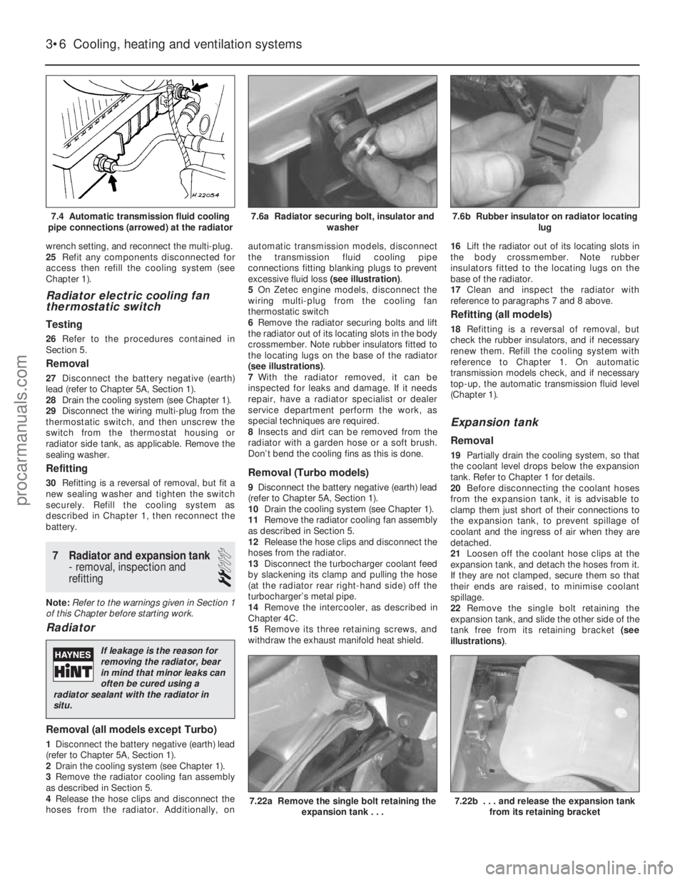
4 Release the hose clips and disconnect the
hoses from the radiator. Additionally, on automatic transmission models, disconnect
the transmission fluid cooling pipe
connections fitting blanking plugs to prevent
excessive fluid loss
(see illustration).
5 On Zetec engine models, disconnect the
wiring multi-plug from the cooling fan
thermostatic switch
6 Remove the radiator securing bolts and lift
the radiator out of its locating slots in the body
crossmember. Note rubber insulators fitted to
the locating lugs on the base of the radiator
(see illustrations) .
7 With the radiator removed, it can be
inspected for leaks and damage. If it needs
repair, have a radiator specialist or dealer
service department perform the work, as
special techniques are required.
8 Insects and dirt can be removed from the
radiator with a garden hose or a soft brush.
Don’t bend the cooling fins as this is done.
Removal (Turbo models)
9 Disconnect the battery negative (earth) lead
(refer to Chapter 5A, Section 1).
10 Drain the cooling system (see Chapter 1).
11 Remove the radiator cooling fan assembly
as described in Section 5.
12 Release the hose clips and disconnect the
hoses from the radiator.
13 Disconnect the turbocharger coolant feed
by slackening its clamp and pulling the hose
(at the radiator rear right-hand side) off the
turbocharger’s metal pipe.
14 Remove the intercooler, as described in
Chapter 4C.
15 Remove its three retaining screws, and
withdraw the exhaust manifold heat shield. 16
Lift the radiator out of its locating slots in
the body crossmember. Note rubber
insulators fitted to the locating lugs on the
base of the radiator.
17 Clean and inspect the radiator with
reference to paragraphs 7 and 8 above.
Refitting (all models)
18 Refitting is a reversal of removal, but
check the rubber insulators, and if necessary
renew them. Refill the cooling system with
reference to Chapter 1. On automatic
transmission models check, and if necessary
top-up, the automatic transmission fluid level
(Chapter 1).
Expansion tank
Removal
19 Partially drain the cooling system, so that
the coolant level drops below the expansion
tank. Refer to Chapter 1 for details.
20 Before disconnecting the coolant hoses
from the expansion tank, it is advisable to
clamp them just short of their connections to
the expansion tank, to prevent spillage of
coolant and the ingress of air when they are
detached.
21 Loosen off the coolant hose clips at the
expansion tank, and detach the hoses from it.
If they are not clamped, secure them so that
their ends are raised, to minimise coolant
spillage.
22 Remove the single bolt retaining the
expansion tank, and slide the other side of the
tank free from its retaining bracket (see
illustrations) .
3•6Cooling, heating and ventilation systems
7.22b . . . and release the expansion tank
from its retaining bracket7.22a Remove the single bolt retaining the expansion tank . . .
7.6b Rubber insulator on radiator locating lug7.6a Radiator securing bolt, insulator andwasher7.4 Automatic transmission fluid cooling
pipe connections (arrowed) at the radiator
1595Ford Fiesta Remake
If leakage is the reason for
removing the radiator, bear
in mind that minor leaks can
often be cured using a
radiator sealant with the radiator in
situ.
procarmanuals.com
http://vnx.su