1989 FORD FIESTA coolant level
[x] Cancel search: coolant levelPage 120 of 296
16Prise out the tamperproof seal covering
the fuel mixture screw, then undo and remove
the mixture screw.
Cleaning and inspection
17 Wash the carburettor components,
drillings and passages with clean petrol, then
blow them dry using a low-pressure air line. A
high-pressure air line must not be applied to
the accelerator pump discharge assembly or
the pump supply valve, as they each contain a
rubber Vernay valve, and these can easily be
damaged under high pressure. Never use a
piece of wire for cleaning purposes.
18 Examine all of the carburettor
components for signs of damage or wear,
paying particular attention to the diaphragms,
throttle spindle and plates, needle valve and
mixture screw; the power valve jet is adjacent
to the primary main jet. Renew all
diaphragms, sealing washers and gaskets as
a matter of course.
Reassembly
19 Refit the fuel mixture screw by fully
winding the screw in, then unwinding three
turns to give an approximate setting.
20 Refit the power valve assembly ensuring
that the diaphragm lies flat, and that the
vacuum gallery lines up correctly with the
diaphragm and housing.
21 Reassemble the secondary barrel
diaphragm into its housing, ensuring that
the diaphragm lies flat and that the vacuum
gallery lines up with the diaphragm and
housing. Also, to assist with installation, do
not reconnect its operating rod until the cover
has been secured.
22 Refit the throttle kicker mounting bracket.
23 Refit the anti-dieseling (fuel cut-off)
solenoid, using a new sealing washer.
24 Refit the accelerator pump assembly,
ensuring that the diaphragm lies flat and is not
kinked.
25 Reassemble the throttle kicker, ensuring
that the diaphragm lies flat and that the relative position of the diaphragm operating
link to the throttle kicker cover is correct. Fully
attach the throttle kicker assembly.
26
Refit the main and idle jets, making
reference to the notes taken during
dismantling to ensure correct fitted locations.
27 Reassemble the carburettor upper body
as described in the following paragraphs.
28 Refit the needle valve housing (using a
new washer if applicable).
29 Refit the needle valve and float assembly,
having ensured that the float tag locates
below the spring clip on the needle valve.
Insert the float retaining pin to secure.
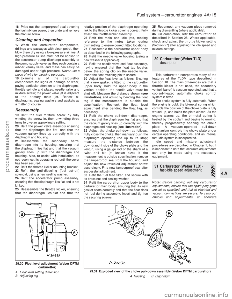
30 Adjust the float level as follows. Ensuring
that a new gasket is fitted to the carburettor
upper body, hold the upper body in the
vertical position; the needle valve must be
shut off. Measure the distance shown (see
illustration) , and adjust by bending the float
tag if the measurement is outside the
specification. Recheck the float level
adjustment after bending the float tag, as
necessary.
31 Refit the choke pull-down diaphragm,
ensuring that the diaphragm lies flat and that
the vacuum gallery lines up correctly with the
diaphragm and housing (see illustration).
32 Adjust the choke pull-down as follows.
Fully close the choke, then manually push the
diaphragm operating rod up to its stop;
measure the distance between the
downdraught side of the choke plate and the
venturi, using a gauge rod or the shank of a
twist drill bit (of known size). If the
measurement is outside specification, remove
the tamperproof seal from the housing, and
adjust the now revealed adjustment screw
accordingly. Fit a new tamperproof seal after
successful adjustment.
33 Refit the fuel feed filter, and secure with
its brass nut and sealing washer.
34 Refit the carburettor upper body to the
carburettor main body, ensuring that its new
gasket seats correctly and that the float does
not foul during assembly. Insert and tighten
the securing screws. 35
Reconnect any vacuum pipes removed
during dismantling (where applicable).
36 On completion, refit the carburettor as
described in Section 28. Where applicable,
check and adjust the throttle kicker setting
(Section 27) after adjusting the idle speed and
mixture settings.
30 Carburettor (Weber TLD) -
description
This carburettor incorporates many of the
features of the TLDM type described in
Section 18. The main differences are that a
throttle kicker is not used, the secondary
venturi (barrel) is vacuum-operated, and that a
coolant-heated automatic choke control
system is fitted. The choke system is fully automatic. When
the engine is cold, the bi-metal spring which
controls the position of the choke plate is fully
wound up, and holds the plate closed. As the
engine warms up, the bi-metal spring is
heated by the coolant and begins to unwind,
thereby progressively opening the choke
plate. A vacuum-operated pull-down
mechanism controls the choke plate under
certain operating conditions, and an internal
fast-idle system is incorporated. Idle speed and mixture adjustment
procedures are described in Chapter 1, but it
is important to note that accurate adjustments
can only be made using the necessary
equipment.
31 Carburettor (Weber TLD) -
fast-idle speed adjustment
4
Note: Before carrying out any carburettor
adjustments, ensure that the spark plug gaps
are set as specified, and that all electrical and
vacuum connections are secure. To carry out
checks and adjustments, an accurate
Fuel system – carburettor engines 4A•15
29.31 Exploded view of the choke pull-down assembly (Weber DFTM carbur\
ettor)
A Housing B Diaphragm
29.30 Float level adjustment (Weber DFTMcarburettor)
A Float level setting dimension
B Adjusting tag
4A
1595Ford Fiesta Remakeprocarmanuals.com
http://vnx.su
Page 121 of 296
tachometer and an exhaust gas analyser (CO
meter) will be required.
1Check that the idle speed and mixture
settings are as specified (as described in
Chapter 1). These must be correct before
checking/adjusting the fast-idle speed.
2 Switch the engine off, then remove the air
cleaner as described in Section 2.
3 With the engine at its normal operating
temperature and a tachometer connected in
accordance with its manufacturer’s
instructions, hold the throttle linkage partly
open, then close the choke plate until the fast-
idle adjusting screw aligns with the third
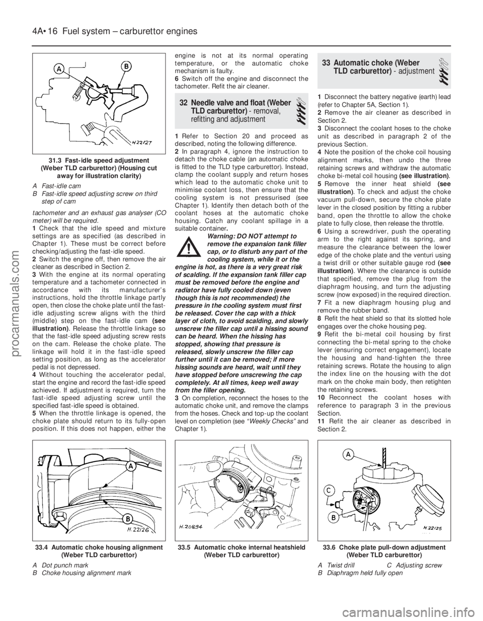
(middle) step on the fast-idle cam (see
illustration) . Release the throttle linkage so
that the fast-idle speed adjusting screw rests
on the cam. Release the choke plate. The
linkage will hold it in the fast-idle speed
setting position, as long as the accelerator
pedal is not depressed.
4 Without touching the accelerator pedal,
start the engine and record the fast-idle speed
achieved. If adjustment is required, turn the
fast-idle speed adjusting screw until the
specified fast-idle speed is obtained.
5 When the throttle linkage is opened, the
choke plate should return to its fully-open
position. If this does not happen, either the engine is not at its normal operating
temperature, or the automatic choke
mechanism is faulty.
6
Switch off the engine and disconnect the
tachometer. Refit the air cleaner.
32 Needle valve and float (Weber
TLD carburettor) - removal,
refitting and adjustment
4
1 Refer to Section 20 and proceed as
described, noting the following difference.
2 In paragraph 4, ignore the instruction to
detach the choke cable (an automatic choke
is fitted to the TLD type carburettor). Instead,
clamp the coolant supply and return hoses
which lead to the automatic choke unit to
minimise coolant loss, then ensure that the
cooling system is not pressurised (see
Chapter 1). Identify then detach both of the
coolant hoses at the automatic choke
housing. Catch any coolant spillage in a
suitable container .
Warning: DO NOT attempt to
remove the expansion tank filler
cap, or to disturb any part of the
cooling system, while it or the
engine is hot, as there is a very great risk
of scalding. If the expansion tank filler cap
must be removed before the engine and
radiator have fully cooled down (even
though this is not recommended) the
pressure in the cooling system must first
be released. Cover the cap with a thick
layer of cloth, to avoid scalding, and slowly
unscrew the filler cap until a hissing sound
can be heard. When the hissing has
stopped, showing that pressure is
released, slowly unscrew the filler cap
further until it can be removed; if more
hissing sounds are heard, wait until they
have stopped before unscrewing the cap
completely. At all times, keep well away
from the filler opening.
3 On completion, reconnect the hoses to the
automatic choke unit, and remove the clamps
from the hoses. Check and top-up the coolant
level on completion (see “Weekly Checks”and
Chapter 1).
33 Automatic choke (Weber TLD carburettor) - adjustment
3
1Disconnect the battery negative (earth) lead
(refer to Chapter 5A, Section 1).
2 Remove the air cleaner as described in
Section 2.
3 Disconnect the coolant hoses to the choke
unit as described in paragraph 2 of the
previous Section.
4 Note the position of the choke coil housing
alignment marks, then undo the three
retaining screws and withdraw the automatic
choke bi-metal coil housing (see illustration).
5 Remove the inner heat shield (see
illustration) . To check and adjust the choke
vacuum pull-down, secure the choke plate
lever in the closed position by fitting a rubber
band, open the throttle to allow the choke
plate to fully close, then release the throttle.
6 Using a screwdriver, push the operating
arm to the right against its spring, and
measure the clearance between the lower
edge of the choke plate and the venturi using
a twist drill or other suitable gauge rod (see
illustration) . Where the clearance is outside
that specified, remove the plug from the
diaphragm housing, and turn the adjusting
screw (now exposed) in the required direction.
7 Fit a new diaphragm housing plug and
remove the rubber band.
8 Refit the heat shield so that its slotted hole
engages over the choke housing peg.
9 Refit the bi-metal coil housing by first
connecting the bi-metal spring to the choke
lever (ensuring correct engagement), locate
the housing and hand-tighten the three
retaining screws. Rotate the housing to align
the index line on the housing with the dot
mark on the choke main body, then retighten
the retaining screws.
10 Reconnect the coolant hoses with
reference to paragraph 3 in the previous
Section.
11 Refit the air cleaner as described in
Section 2.
4A•16 Fuel system – carburettor engines
33.6 Choke plate pull-down adjustment (Weber TLD carburettor)
A Twist drill C Adjusting screw
B Diaphragm held fully open33.5 Automatic choke internal heatshield (Weber TLD carburettor)33.4 Automatic choke housing alignment(Weber TLD carburettor)
A Dot punch mark
B Choke housing alignment mark
1595Ford Fiesta Remake
31.3 Fast-idle speed adjustment
(Weber TLD carburettor) (Housing cut away for illustration clarity)
A Fast-idle cam
B Fast-idle speed adjusting screw on third step of cam
procarmanuals.com
http://vnx.su
Page 123 of 296
As it is detached, plug the end of the hose to
prevent excessive fuel spillage and the ingress
of dirt. Where a crimped type hose clip is fitted,
cut it free, taking care not to damage the hose;
a new screw type clip will need to be obtained
to replace the crimped clip during reassembly.
7Disconnect the relevant vacuum pipes from
the carburettor. As they are detached, label
them to ensure correct reassembly.
8 Unscrew and remove the four Torx-type
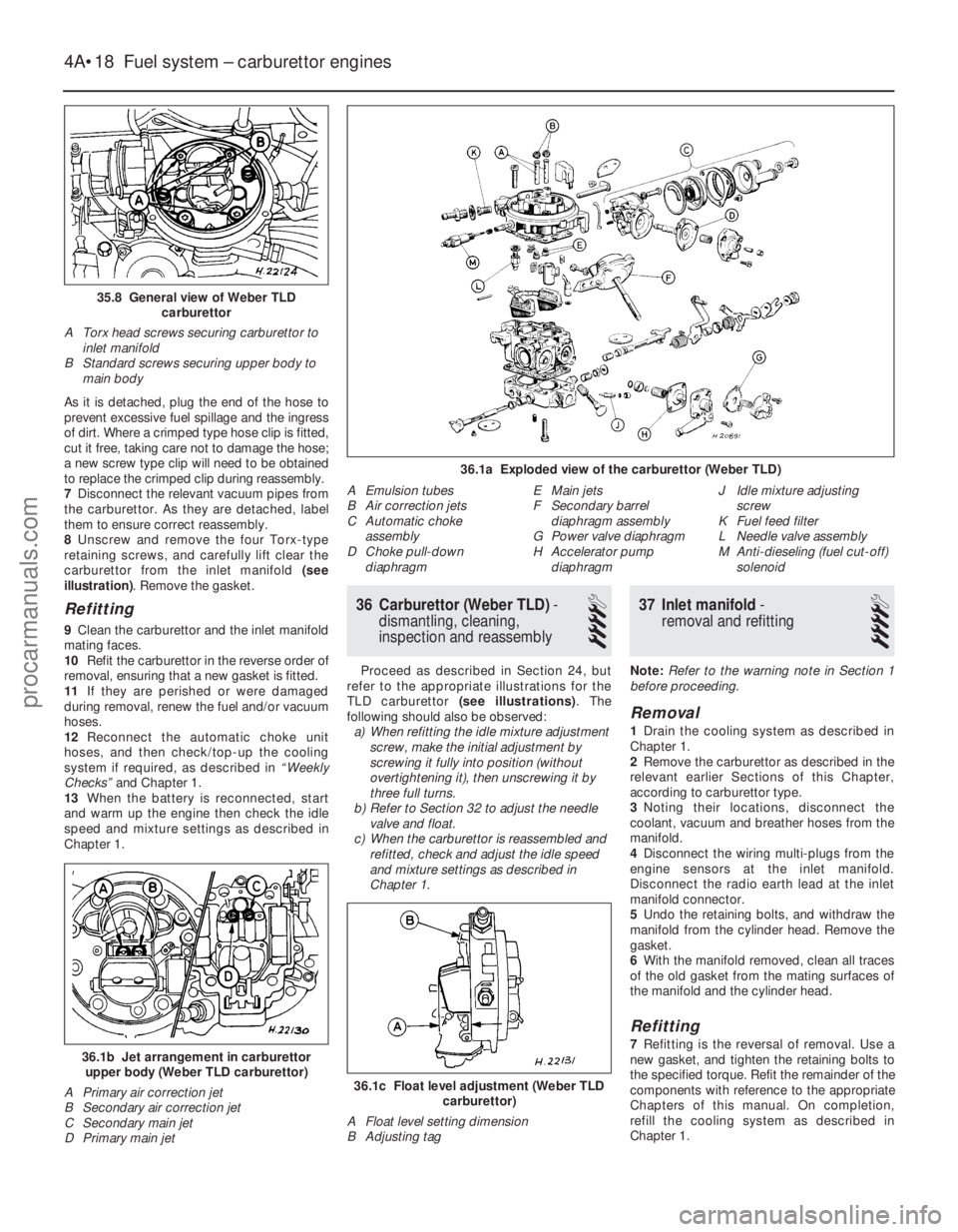
retaining screws, and carefully lift clear the
carburettor from the inlet manifold (see
illustration) . Remove the gasket.
Refitting
9Clean the carburettor and the inlet manifold
mating faces.
10 Refit the carburettor in the reverse order of
removal, ensuring that a new gasket is fitted.
11 If they are perished or were damaged
during removal, renew the fuel and/or vacuum
hoses.
12 Reconnect the automatic choke unit
hoses, and then check/top-up the cooling
system if required, as described in “Weekly
Checks” and Chapter 1.
13 When the battery is reconnected, start
and warm up the engine then check the idle
speed and mixture settings as described in
Chapter 1.
36 Carburettor (Weber TLD) -
dismantling, cleaning,
inspection and reassembly
4
Proceed as described in Section 24, but
refer to the appropriate illustrations for the
TLD carburettor (see illustrations) . The
following should also be observed: a) When refitting the idle mixture adjustment
screw, make the initial adjustment by
screwing it fully into position (without
overtightening it), then unscrewing it by
three full turns.
b) Refer to Section 32 to adjust the needle
valve and float.
c) When the carburettor is reassembled and refitted, check and adjust the idle speed
and mixture settings as described in
Chapter 1.
37 Inlet manifold -
removal and refitting
4
Note: Refer to the warning note in Section 1
before proceeding.
Removal
1 Drain the cooling system as described in
Chapter 1.
2 Remove the carburettor as described in the
relevant earlier Sections of this Chapter,
according to carburettor type.
3 Noting their locations, disconnect the
coolant, vacuum and breather hoses from the
manifold.
4 Disconnect the wiring multi-plugs from the
engine sensors at the inlet manifold.
Disconnect the radio earth lead at the inlet
manifold connector.
5 Undo the retaining bolts, and withdraw the
manifold from the cylinder head. Remove the
gasket.
6 With the manifold removed, clean all traces
of the old gasket from the mating surfaces of
the manifold and the cylinder head.
Refitting
7 Refitting is the reversal of removal. Use a
new gasket, and tighten the retaining bolts to
the specified torque. Refit the remainder of the
components with reference to the appropriate
Chapters of this manual. On completion,
refill the cooling system as described in
Chapter 1.
36.1c Float level adjustment (Weber TLD carburettor)
A Float level setting dimension
B Adjusting tag
36.1b Jet arrangement in carburettor upper body (Weber TLD carburettor)
A Primary air correction jet
B Secondary air correction jet
C Secondary main jet
D Primary main jet
4A•18 Fuel system – carburettor engines
36.1a Exploded view of the carburettor (Weber TLD)
A Emulsion tubes
B Air correction jets
C Automatic choke assembly
D Choke pull-down
diaphragm E Main jets
F Secondary barrel
diaphragm assembly
G Power valve diaphragm
H Accelerator pump
diaphragm J Idle mixture adjusting
screw
K Fuel feed filter
L Needle valve assembly
M Anti-dieseling (fuel cut-off) solenoid
35.8 General view of Weber TLD carburettor
A Torx head screws securing carburettor to inlet manifold
B Standard screws securing upper body to main body
1595Ford Fiesta Remakeprocarmanuals.com
http://vnx.su
Page 156 of 296
d)Refit the remaining parts in the reverse
order of removal. Tighten all fasteners to
the specified torque wrench settings
where given.
e) Where drained, refill the cooling system (see Chapter 1).
f) Run the engine, and check for exhaust
leaks. Check the coolant level when fully
warmed-up to normal operating
temperature.
4 Catalytic converter - general
information and precautions
The catalytic converter is a reliable and
simple device, which needs no maintenance
in itself, but there are some facts of which an
owner should be aware if the converter is to
function properly for its full service life. a) DO NOT use leaded petrol in a vehicle equipped with a catalytic converter - the
lead will coat the precious metals,
reducing their converting efficiency, and
will eventually destroy the converter.
b) Always keep the ignition and fuel systems
well-maintained in accordance with the
manufacturer’s schedule (see Chapter 1).
c) If the engine develops a misfire, do not drive the vehicle at all (or at least as little
as possible) until the fault is cured.
d) DO NOT push - or tow-start the vehicle -
this will soak the catalytic converter in
unburned fuel, causing it to overheat
when the engine does start.
e) DO NOT switch off the ignition at high engine speeds, ie do not “blip” the
throttle immediately before switching off.
f) DO NOT use fuel or engine oil additives - these may contain substances harmful to
the catalytic converter.
g) DO NOT continue to use the vehicle if the
engine burns oil to the extent of leaving a
visible trail of blue smoke.
h) Remember that the catalytic converter
operates at very high temperatures. DO
NOT, therefore, park the vehicle in dry
undergrowth, over long grass or piles of
dead leaves, after a long run.
I) Remember that the catalytic converter is FRAGILE. Do not strike it with tools
during servicing work.
j) In some cases, a sulphurous smell (like
that of rotten eggs) may be noticed from
the exhaust. This is common to many
catalytic converter-equipped vehicles.
Once the vehicle has covered a few
thousand miles, the problem should
disappear. Low quality fuel with a high
sulphur content will exacerbate this effect.
k) The catalytic converter used on a well-
maintained and well-driven vehicle should
last for between 50 000 and
100 000 miles. If the converter is no
longer effective, it must be renewed.
5 Positive crankcase ventilation system - checking
and component renewal
2
Checking
1 Checking procedures for the system
components are included in Chapter 1.
Component renewal - all
engines except Zetec
Air cleaner components
2 See Chapter 1.
Filter/oil separator and hoses
3All the components relating to the positive
crankcase ventilation system, with the
exception of the HCS engine filter/adapter
located on the underside of the air cleaner,
may be removed by simple disconnection and
withdrawal (having noted all connections for
subsequent refitting).
4 The refitting of all components is a reversal
of the removal procedure, ensuring that the
connections are correctly made.
Component renewal - Zetec
engines
Air cleaner components
5 See Chapter 1.
Positive Crankcase Ventilation (PCV)
valve
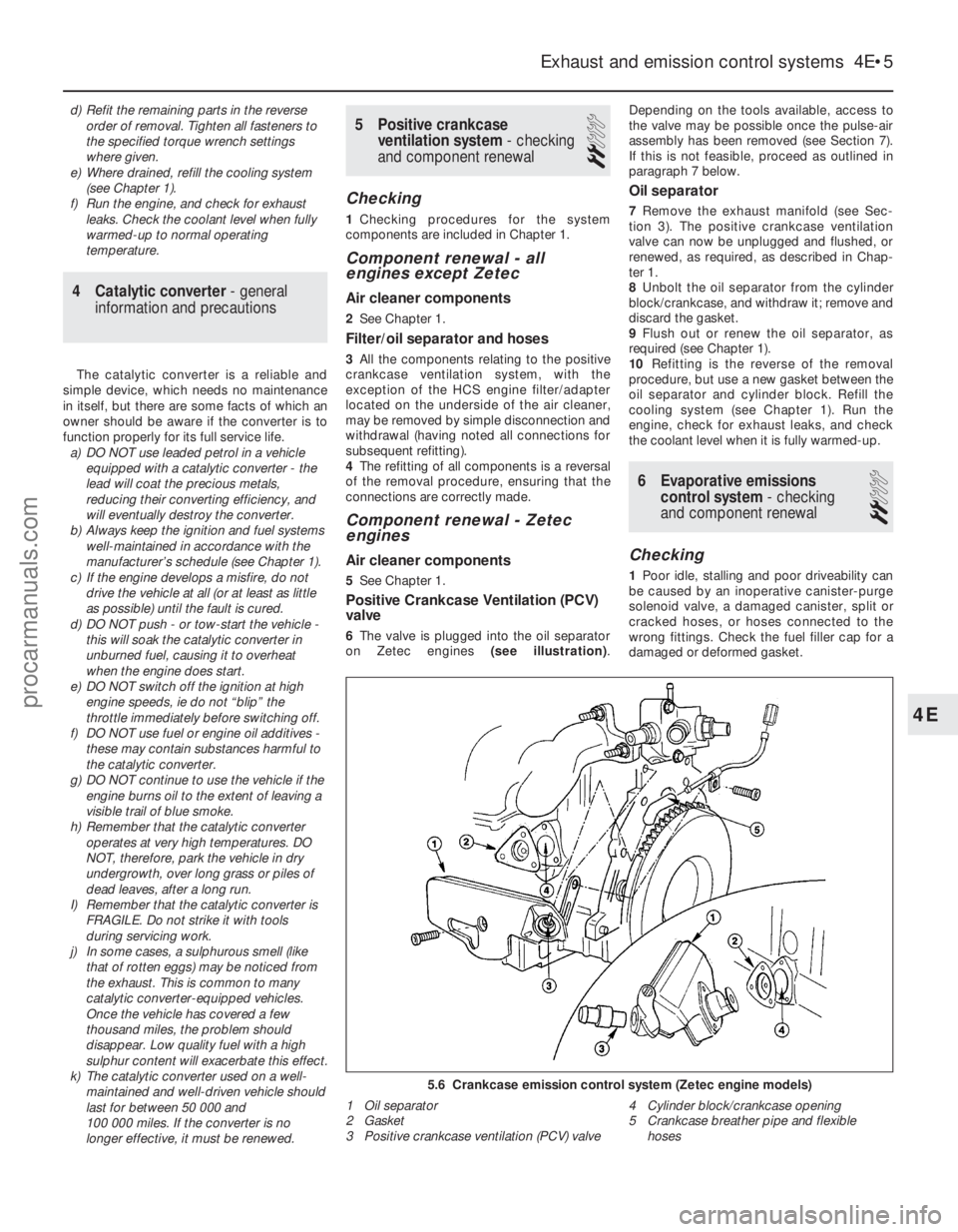
6The valve is plugged into the oil separator
on Zetec engines (see illustration).Depending on the tools available, access to
the valve may be possible once the pulse-air
assembly has been removed (see Section 7).
If this is not feasible, proceed as outlined in
paragraph 7 below.
Oil separator
7
Remove the exhaust manifold (see Sec-
tion 3). The positive crankcase ventilation
valve can now be unplugged and flushed, or
renewed, as required, as described in Chap-
ter 1.
8 Unbolt the oil separator from the cylinder
block/crankcase, and withdraw it; remove and
discard the gasket.
9 Flush out or renew the oil separator, as
required (see Chapter 1).
10 Refitting is the reverse of the removal
procedure, but use a new gasket between the
oil separator and cylinder block. Refill the
cooling system (see Chapter 1). Run the
engine, check for exhaust leaks, and check
the coolant level when it is fully warmed-up.
6 Evaporative emissions control system - checking
and component renewal
2
Checking
1 Poor idle, stalling and poor driveability can
be caused by an inoperative canister-purge
solenoid valve, a damaged canister, split or
cracked hoses, or hoses connected to the
wrong fittings. Check the fuel filler cap for a
damaged or deformed gasket.
Exhaust and emission control systems 4E•5
5.6 Crankcase emission control system (Zetec engine models)
1 Oil separator
2 Gasket
3 Positive crankcase ventilation (PCV) valve 4 Cylinder block/crankcase opening
5 Crankcase breather pipe and flexible
hoses
4E
1595Ford Fiesta Remakeprocarmanuals.com
http://vnx.su
Page 282 of 296
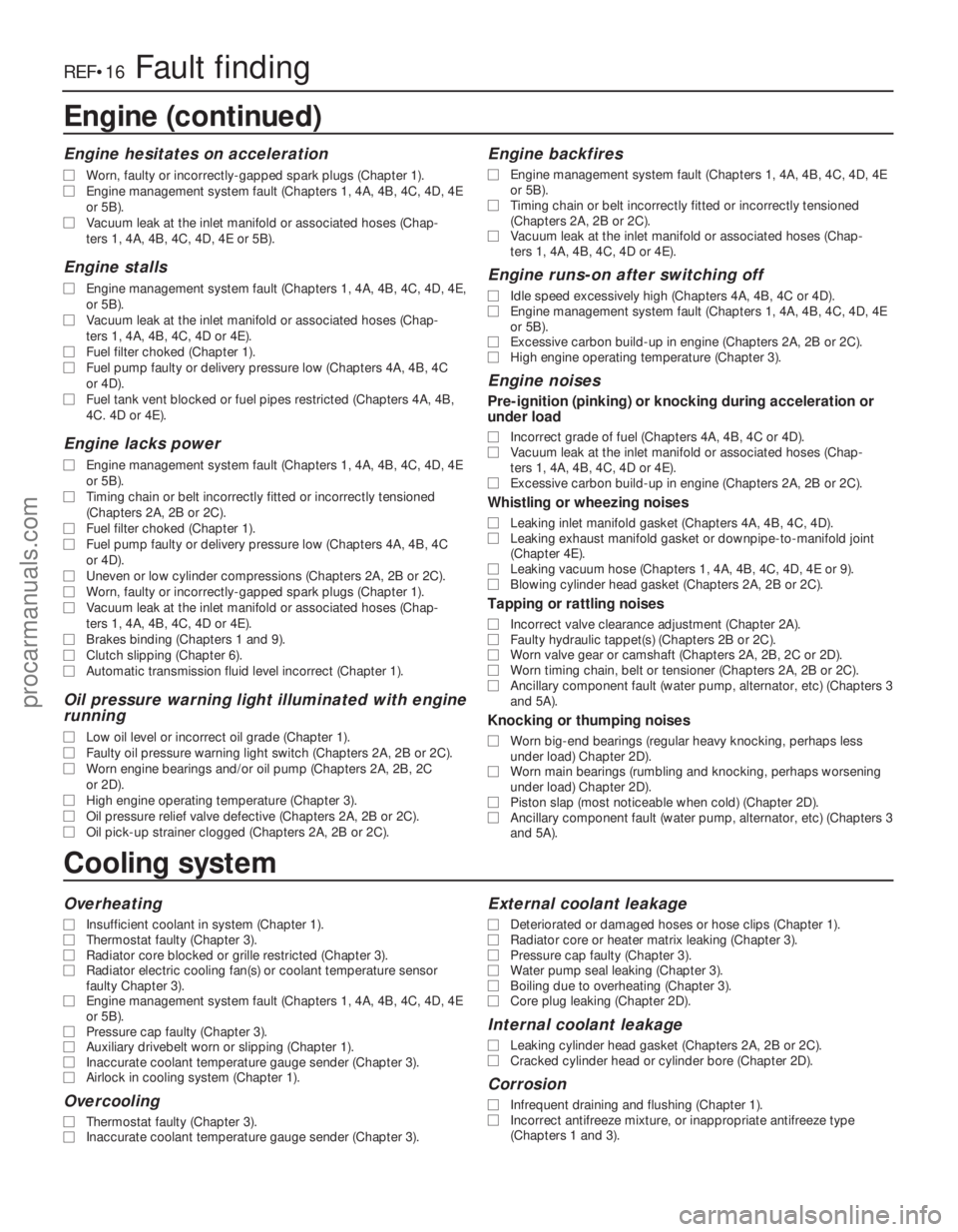
1595 Ford Fiesta Remake
REF•16Fault finding
Cooling system
Overheating
m
mInsufficient coolant in system (Chapter 1).
m
m Thermostat faulty (Chapter 3).
m
m Radiator core blocked or grille restricted (Chapter 3).
m
m Radiator electric cooling fan(s) or coolant temperature sensor
faulty Chapter 3).
m m Engine management system fault (Chapters 1, 4A, 4B, 4C, 4D, 4E
or 5B).
m m Pressure cap faulty (Chapter 3).
m
m Auxiliary drivebelt worn or slipping (Chapter 1).
m
m Inaccurate coolant temperature gauge sender (Chapter 3).
m
m Airlock in cooling system (Chapter 1).
Overcooling
m
mThermostat faulty (Chapter 3).
m
m Inaccurate coolant temperature gauge sender (Chapter 3).
External coolant leakage
m
mDeteriorated or damaged hoses or hose clips (Chapter 1).
m
m Radiator core or heater matrix leaking (Chapter 3).
m
m Pressure cap faulty (Chapter 3).
m
m Water pump seal leaking (Chapter 3).
m
m Boiling due to overheating (Chapter 3).
m
m Core plug leaking (Chapter 2D).
Internal coolant leakage
m
mLeaking cylinder head gasket (Chapters 2A, 2B or 2C).
m
m Cracked cylinder head or cylinder bore (Chapter 2D).
Corrosion
m
mInfrequent draining and flushing (Chapter 1).
m
m Incorrect antifreeze mixture, or inappropriate antifreeze type
(Chapters 1 and 3).
Engine (continued)
Engine hesitates on acceleration
m
m Worn, faulty or incorrectly-gapped spark plugs (Chapter 1).
m
m Engine management system fault (Chapters 1, 4A, 4B, 4C, 4D, 4E
or 5B).
m m Vacuum leak at the inlet manifold or associated hoses (Chap-
ters 1, 4A, 4B, 4C, 4D, 4E or 5B).
Engine stalls
m mEngine management system fault (Chapters 1, 4A, 4B, 4C, 4D, 4E,
or 5B).
m m Vacuum leak at the inlet manifold or associated hoses (Chap-
ters 1, 4A, 4B, 4C, 4D or 4E).
m m Fuel filter choked (Chapter 1).
m
m Fuel pump faulty or delivery pressure low (Chapters 4A, 4B, 4C
or 4D).
m m Fuel tank vent blocked or fuel pipes restricted (Chapters 4A, 4B,
4C. 4D or 4E).
Engine lacks power
m mEngine management system fault (Chapters 1, 4A, 4B, 4C, 4D, 4E
or 5B).
m m Timing chain or belt incorrectly fitted or incorrectly tensioned
(Chapters 2A, 2B or 2C).
m m Fuel filter choked (Chapter 1).
m
m Fuel pump faulty or delivery pressure low (Chapters 4A, 4B, 4C
or 4D).
m m Uneven or low cylinder compressions (Chapters 2A, 2B or 2C).
m
m Worn, faulty or incorrectly-gapped spark plugs (Chapter 1).
m
m Vacuum leak at the inlet manifold or associated hoses (Chap-
ters 1, 4A, 4B, 4C, 4D or 4E).
m m Brakes binding (Chapters 1 and 9).
m
m Clutch slipping (Chapter 6).
m
m Automatic transmission fluid level incorrect (Chapter 1).
Oil pressure warning light illuminated with engine
running
m mLow oil level or incorrect oil grade (Chapter 1).
m
m Faulty oil pressure warning light switch (Chapters 2A, 2B or 2C).
m
m Worn engine bearings and/or oil pump (Chapters 2A, 2B, 2C
or 2D).
m m High engine operating temperature (Chapter 3).
m
m Oil pressure relief valve defective (Chapters 2A, 2B or 2C).
m
m Oil pick-up strainer clogged (Chapters 2A, 2B or 2C).
Engine backfires
m
mEngine management system fault (Chapters 1, 4A, 4B, 4C, 4D, 4E
or 5B).
m m Timing chain or belt incorrectly fitted or incorrectly tensioned
(Chapters 2A, 2B or 2C).
m m Vacuum leak at the inlet manifold or associated hoses (Chap-
ters 1, 4A, 4B, 4C, 4D or 4E).
Engine runs-on after switching off
m mIdle speed excessively high (Chapters 4A, 4B, 4C or 4D).
m
m Engine management system fault (Chapters 1, 4A, 4B, 4C, 4D, 4E
or 5B).
m m Excessive carbon build-up in engine (Chapters 2A, 2B or 2C).
m
m High engine operating temperature (Chapter 3).
Engine noises
Pre-ignition (pinking) or knocking during acceleration or
under load
m mIncorrect grade of fuel (Chapters 4A, 4B, 4C or 4D).
m
m Vacuum leak at the inlet manifold or associated hoses (Chap-
ters 1, 4A, 4B, 4C, 4D or 4E).
m m Excessive carbon build-up in engine (Chapters 2A, 2B or 2C).
Whistling or wheezing noises
m
mLeaking inlet manifold gasket (Chapters 4A, 4B, 4C, 4D).
m
m Leaking exhaust manifold gasket or downpipe-to-manifold joint
(Chapter 4E).
m m Leaking vacuum hose (Chapters 1, 4A, 4B, 4C, 4D, 4E or 9).
m
m Blowing cylinder head gasket (Chapters 2A, 2B or 2C).
Tapping or rattling noises
m
mIncorrect valve clearance adjustment (Chapter 2A).
m
m Faulty hydraulic tappet(s) (Chapters 2B or 2C).
m
m Worn valve gear or camshaft (Chapters 2A, 2B, 2C or 2D).
m
m Worn timing chain, belt or tensioner (Chapters 2A, 2B or 2C).
m
m Ancillary component fault (water pump, alternator, etc) (Chapters 3
and 5A).
Knocking or thumping noises
m mWorn big-end bearings (regular heavy knocking, perhaps less
under load) Chapter 2D).
m m Worn main bearings (rumbling and knocking, perhaps worsening
under load) Chapter 2D).
m m Piston slap (most noticeable when cold) (Chapter 2D).
m
m Ancillary component fault (water pump, alternator, etc) (Chapters 3
and 5A).
procarmanuals.com
http://vnx.su