1988 PONTIAC FIERO seats
[x] Cancel search: seatsPage 1788 of 1825
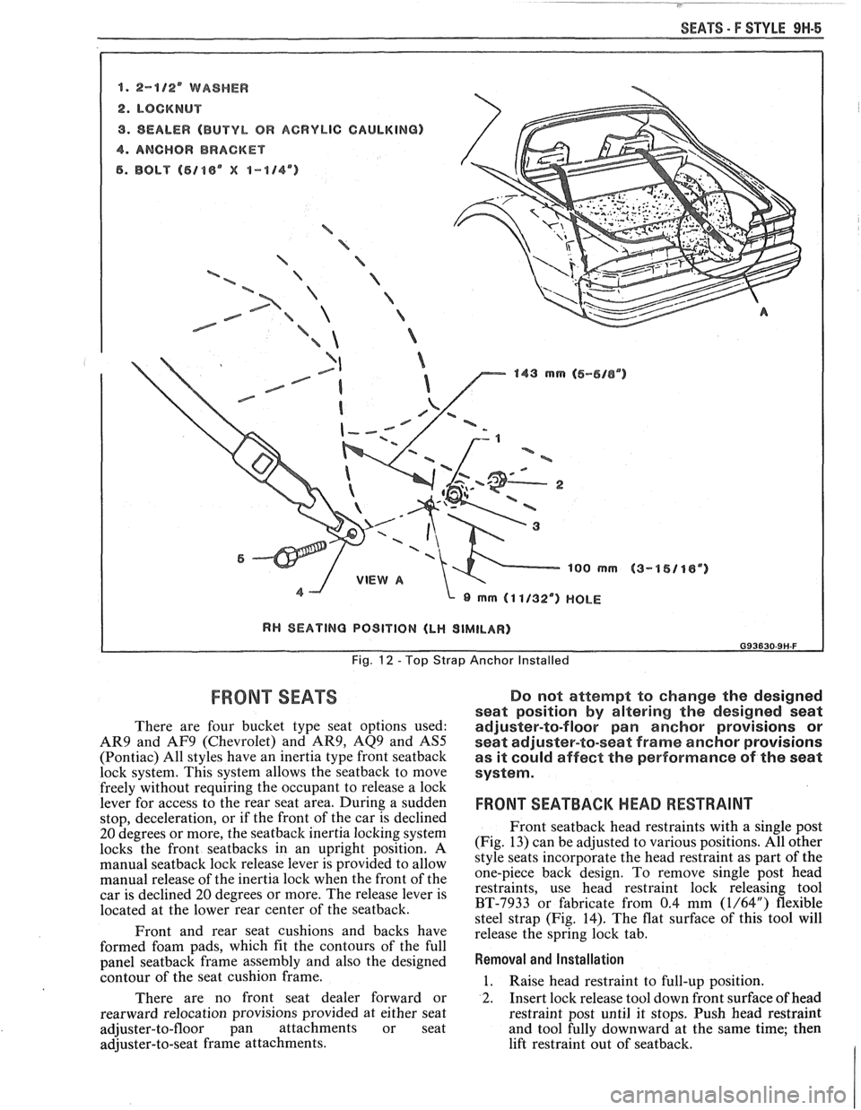
SEATS - F STYLE 9H-5
8. 2-8/2' WASHER
2. LOCKNUT
9. SEALER (BUTYL OR ACRYLIC CAULKING)
4. ANCHOR BRACKET
6. BOLT (5188" X 1-114")
a B -% ='-a
/ '%
/ e-5- B
a 143 mrn (6-616") 143 mrn (6-616")
~QO rnm 1QO rnm
I RH SEATING PO9lVlON (LH SIMILAR) I
Fig. 12 - Top Strap Anchor Installed
FRONT SEATS Do not attempt to change the designed
seat position
by altering the designed seat
There are four bucket type seat options used: adjuster-to-floor pan anchor provisions or
AR9 and AF9 (Chevrolet) and AR9, AQ9 and AS5 seat adjuster-to-seat frame anchor provisions
(Pontiac) All styles have an inertia type front seatback as it could affect the performance of the seat
lock system. This system allows the seatback to move system.
freelv without reauiring the occupant to release a lock
leve; for access to the rear seat a;ea. During a sudden
stop, deceleration, or if the front of the car is declined
20 degrees or more, the seatback inertia locking system
locks the front seatbacks in an upright position. A
manual
seatback lock release lever is provided to allow
manual release of the inertia lock when the front of the
car is declined
20 degrees or more. The release lever is
located at the lower rear center of the seatback.
Front and rear seat cushions and backs have
formed foam pads, which
fit the contours of the full
panel
seatback frame assembly and also the designed
contour of the seat cushion frame.
There are no front seat dealer forward or
rearward relocation provisions provided at either seat
adjuster-to-floor pan attachments or seat
adjuster-to-seat frame attachments.
FRONT SEATBACM HEAD RESTRAINT
Front seatback head restraints with a single post
(Fig. 13) can be adjusted to various positions. All other
style seats incorporate the head restraint as part of the
one-piece back design. To remove single post head
restraints, use head restraint lock releasing tool
BT-7933 or fabricate from 0.4 mm
(1/64") flexible
steel strap (Fig. 14). The flat surface of this tool will
release the spring lock tab.
Removal and Installation
1. Raise head restraint to full-up position.
2. Insert lock release tool down front surface of head
restraint post until it stops. Push head restraint
and tool fully downward at the same time; then
lift restraint out of seatback.
Page 1789 of 1825
9H-6 SEATS - F STYLE
3. To install head restraint, insert post into guide
and push downward to full-down position. Check
that lock spring engages and prevents head
restraint from being removed.
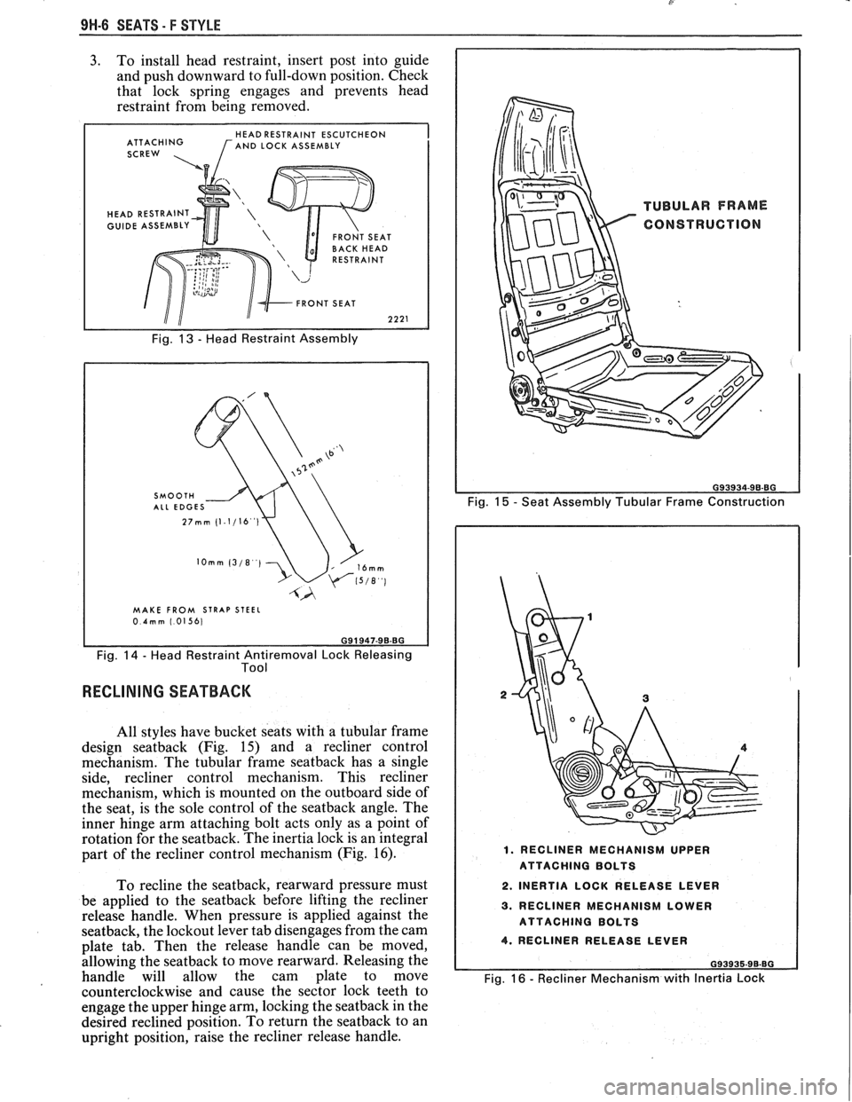
HEAD RESTRAINT ESCUTCHEON
ATTACHING [AND LOCK ASSEMBLY
SCREW ,
HEAD RESTRAINT
GUIDE ASSEMBLY
Fig. 13 - Head Restraint Assembly
MAKE FROM STRAP STEEL 0.4mm 1.01561
Fig. 14 - Head Restraint Antiremoval Lock Releasing
Tool
RECLINING SEATBACK
All styles have bucket seats with a tubular frame
design
seatback (Fig. 15) and a recliner control
mechanism. The tubular frame
seatback has a single
side, recliner control mechanism. This recliner
mechanism, which is mounted on the outboard side of
the seat, is the sole control of the
seatback angle. The
inner hinge arm attaching bolt acts only as a point of
rotation for the seatback. The inertia lock is an integral
part of the recliner control mechanism (Fig.
16).
To recline the seatback, rearward pressure must
be applied to the
seatback before lifting the recliner
release handle. When pressure is applied against the
seatback, the lockout lever tab disengages from the cam
plate tab. Then the release handle can be moved,
allowing the
seatback to move rearward. Releasing the
handle will allow the cam plate to move
counterclockwise and cause the sector lock teeth to
engage the upper hinge arm, locking the
seatback in the
desired reclined position. To return the
seatback to an
upright position, raise the recliner release handle.
Fig. 15 - Seat Assembly Tubular Frame Construction
1. RECLINER MECHANISM UPPER
ATTACHING BOLTS
2. INERTIA LOCK RELEASE LEVER
3. RECLINER MECHANISM LOWER
ATTACHING BOLTS
4. RECLINER RELEASE LEVER
G93935-96-BG
Fig. 16 - Recliner Mechanism with Inertia Lock
Page 1790 of 1825
SEATS - F STYLE 9H-7
~
RECLINER CONTROL MECHANISM
Removal and Installation (Fig. 17)
1. Place reclining seatback in full-up position.
2. Remove
upper recliner mechanism cover.
3. Remove lower recliner mechanism cover.
4. Remove two upper and two lower recliner
mechanism attaching bolts and remove recliner
control mechanism.
5. To install, reverse removal procedure.
FRONT SEATBACK
Removal and Installation (Fig. 17)
1. Place seatback in
full-up position.
2. Move seat to full-forward position.
3. Remove upper recliner mechanism cover.
4. Remove both recliner mechanism upper
attaching bolts.
5. Remove seatback inner hinge arm escutcheon
and attaching bolt and remove seatback.
6. To
install, reverse removal procedure.
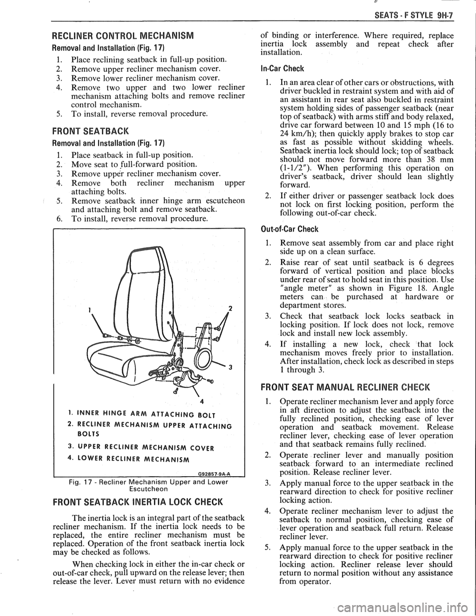
1, INNER HINGE ARM ATTACHING BOLT
2. RECLINER MECHANISM UPPER ATTACHING
3. UPPER RECLINER MECHANISM COVER
4. LOWER RECLINER MECHANISM
G92857-9A-A
Fig. 17 - Recliner Mechanism Upper and Lower
Escutcheon
FRONT SEATBACK INERTIA LOCK CHECK
The inertia lock is an integral part of the seatback
recliner mechanism. If the inertia lock needs to be
replaced, the entire recliner mechanism must be
replaced. Operation of the front
seatback inertia lock
may be checked as follows.
When checking lock in either the in-car check or
out-of-car check, pull upward on the release lever; then
release the lever. Lever must return with no evidence of
binding or interference. Where required, replace
inertia lock assembly and repeat check after
installation.
In-Car Check
1. In an area clear of other cars or obstructions, with
driver buckled in restraint system and with aid of
an assistant in rear seat also buckled in restraint
system holding sides of passenger
seatback (near
top of seatback) with arms stiff and body relaxed,
drive car forward between
10 and 15 mph (16 to
24
km/h); then quickly apply brakes to stop car
as fast as possible without skidding wheels.
Seatback inertia lock should lock; top of seatback
should not move forward more than 38 mm
(1-1/2"). When performing this operation on
driver's seatback, driver should lean slightly
forward.
2. If either driver or passenger
seatback lock does
not lock on first locking position, perform the
following out-of-car check.
Out-of-Car Check
1.
Remove seat assembly from car and place right
side up on a clean surface.
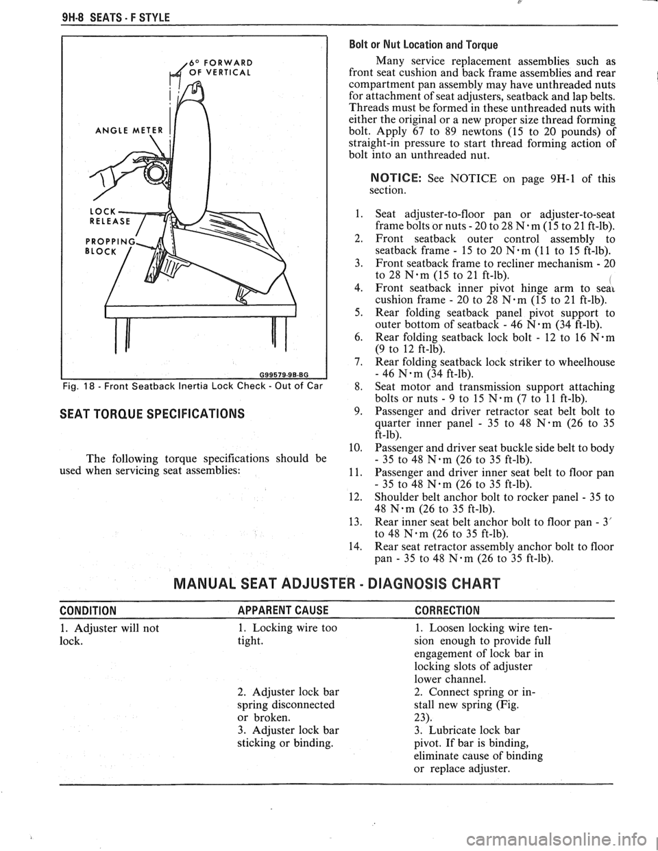
2. Raise rear of seat until seatback is 6 degrees
forward of vertical position and place blocks
under rear of seat to hold seat in this position. Use
"angle meter" as shown in Figure
18. Angle
meters can be purchased at hardware or
department stores.
3. Check that seatbaclc lock locks seatback in
locking position. If lock does not
lock, remove
lock and install new lock assembly.
4. If installing a new lock, check that lock
mechanism moves freely prior to installation.
After installation, check lock as described in steps
1 through 3.
FRONT SEAT MANUAL RECLINER CHECK
1.
Operate recliner mechanism lever and apply force
in aft direction to adjust the
seatback into the
fully reclined position, checking ease of lever
operation and
seatback movement. Release
recliner lever, checking ease of lever operation
and that
seatback remains fully reclined.
2. Operate recliner lever and manually position
seatback forward to an intermediate reclined
position. Release recliner lever.
3. Apply manual force to the upper seatback in the
rearward direction to check for positive recliner
locking action.
4. Operate recliner mechanism lever to adjust the
seatback to normal position, checking ease of
lever operation and
seatback full return. Release
recliner lever.
5. Apply manual force to the upper seatback in the
rearward direction to check for positive recliner
locking action. Recliner release lever should
return to normal position without any assistance
from operator.
Page 1791 of 1825
9H-8 SEATS. F STYLE Bolt or Nut Location and Torque
6O FORWARD Many service replacement assemblies such as
OF VERTICAL front seat cushion and back frame assemblies and rear
compartment pan assembly may have unthreaded nuts
for attachment of seat adjusters,
seatback and lap belts.
Threads must be formed in these unthreaded nuts with
either the original or a new proper size thread forming
ANGLE METER bolt. Apply 67 to 89 newtons (15 to 20 pounds) of
straight-in pressure to start thread forming action of
bolt into an unthreaded nut.
NOTIICE: See NOTICE on page 9H-1 of this
section.
1. Seat adjuster-to-floor pan or adjuster-to-seat
frame bolts or nuts
- 20 to 28 N-m (15 to 21 ft-lb).
2. Front seatback outer control assembly to
seatback frame - 15 to 20 N-m (1 1 to 15 ft-lb).
3. Front
seatback frame to recliner mechanism - 20
to 28
N-m (15 to 21 ft-lb). I 4. Front seatback inner pivot hinge arm to seai
cushion frame - 20 to 28 N.m (15 to 21 ft-lb).
5. Rear folding
seatback panel pivot support to
outer bottom of
seatback - 46 N-m (34 ft-lb).
6. Rear folding
seatback lock bolt - 12 to 16 N.m
(9 to 12 ft-lb).
7. Rear folding
seatback lock striker to wheelhouse
- 46 N.m (34 ft-lb).
Fig. 18 - Front Seatback Inertia Lock Check - Out of Car 8. Seat
motor and transmission support attaching
bolts or nuts
- 9 to 15 N.m (7 to 11 ft-lb).
SEAT TORQUE SPECIFICATIONS 9. Passenger and driver retractor seat belt bolt to
quarter inner panel
- 35 to 48 N-m (26 to 35
ft-lb).
10. Passenger and driver seat buckle side belt to body
The following torque specifications should be
- 35 to 48 N.m (26 to 35 ft-lb).
used when servicing seat assemblies:
11. Passenger and driver inner seat belt to floor pan
- 35 to 48 N.m (26 to 35 ft-lb).
12. Shoulder belt anchor bolt to rocker panel
- 35 to
48
Nam (26 to 35 ft-lb).
13. Rear inner seat belt anchor bolt to floor pan
- 3'
to 48
Nqm (26 to 35 ft-lb).
14. Rear seat retractor assembly anchor bolt to floor
pan
- 35 to 48 N-m (26 to 35 ft-lb).
MANUAL SEAT ADJUSTER - DIAGNOSIS CHART
CONDITION APPARENTCAUSE CORRECTION
1. Adjuster will not 1. Locking wire
too
1. Loosen locking wire ten-
lock. tight. sion enough to provide full
engagement of lock bar in
locking slots of adjuster
lower channel.
2. Adjuster lock bar 2. Connect spring or
in-
spring disconnected stall new spring (Fig.
or broken. 23).
3. Adjuster lock bar 3. Lubricate lock bar
sticking or binding.
pivot. If bar is binding,
eliminate cause of binding
or replace adjuster.
Page 1792 of 1825
SEATS - F STYLE 9H-9
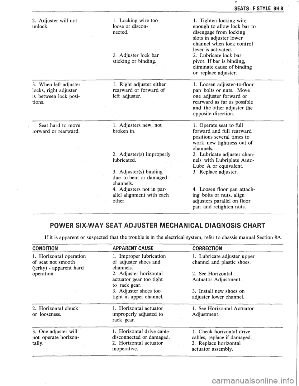
2. Adjuster will not
unlock. 1. Locking wire too
loose or discon-
nected.
2. Adjuster lock bar
sticking or binding.
1. Tighten locking wire
enough to allow lock bar to
disengage from locking
slots in adjuster lower
channel when lock control
lever is activated.
2. Lubricate lock bar
pivot. If bar is binding,
eliminate cause of binding
or replace adjuster.
3. When left adjuster 1. Right adjuster either 1. Loosen adjuster-to-floor
locks, right adjuster rearward or forward of pan bolts or nuts. Move
is between lock posi- left adjuster. one adjuster forward or
tions. rearward
as far as possible
and the other adjuster the
opposite direction.
- --
Seat hard to moye
lorward or rearward.
1. Adjusters new, not
broken in.
2. Adjuster(s) improperly
lubricated.
3. Adjuster(s) binding
due to bent or damaged
channels.
4. Adjusters not in par-
allel alignment with each
other.
1. Operate seat to full
forward and full rearward
positions several times to
work new tightness out of
channels.
2. Lubricate adjuster chan-
nels with Lubriplate
Auto-
Lube A or equivalent.
3. Replace adjuster.
4. Loosen floor pan attach-
ing bolts or nuts, align
adjusters parallel on floor
pan and retighten nuts.
POWER SIX-WAY SEAMADJUSTER MECHANICAL DIAGNOSIS CHART
If it is apparent or suspected that the trouble is in the electrical system, refer to chassis manual Section 8A.
CONDITION APPARENT CAUSE CORRECTION
1. Horizontal operation 1. Improper lubrication 1. Lubricate adjuster upper
of seat not smooth of
adjuster shoes and
channel and plastic shoes.
(jerky)
- apparent hard channels.
operation.
2. Adjuster horizontal 2. See Horizontal
actuator gear too tight
Actuator Adjustment.
to rack gear.
3. Adjuster shoes too 3. Install new shoes on
tight in upper channel.
adjuster lower channel.
2. Horizontal chuck 1. Horizontal actuator 1. See Horizontal Actuator
or looseness. improperly adjusted to Adjustment.
rack gear.
3. One adjuster will 1. Horizontal drive cable 1. Check horizontal drive
not operate horizon- disconnected or damaged. cables, replace if damaged.
tally.
2. Horizontal actuator 2. Replace horizontal
inoperative. actuator assembly.
Page 1793 of 1825
8'
9H-10 SEATS - F STYLE
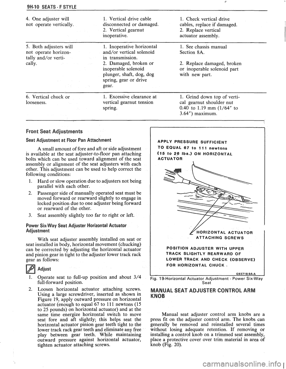
4. One adjuster will 1. Vertical drive cable 1. Check vertical drive
not operate vertically. disconnected or damaged. cables, replace if damaged.
2. Vertical gearnut 2. Replace vertical
inoperative. actuator assembly.
5. Both adjusters will 1. Inoperative horizontal 1. See chassis manual
not operate horizon- and/or vertical solenoid Section
8A.
tally and/or verti- in transmission.
cally. 2. Damaged, broken or 2. Replace damaged, broken
inoperable solenoid or inoperable solenoid part
plunger, shaft, dog, dog
with new part.
spring, gear or drive
gear.
6. Vertical chuck or
1. Excessive clearance at
1. Grind down top of verti-
looseness. vertical
gearnut tension cal gearnut shoulder nut
spring. 0.40 to 1.19 mm
(1/64" to
3.64") maximum.
Front Seat Adjustments
Seat Adjustment at Floor Pan Attachment
A small amount of fore and aft or side adjustment
is available at the seat adjuster-to-floor pan attaching
bolts which can be used toward alignment of the seat
assembly or alignment of the seat adjusters with each
other. This adjustment can be used to help correct the
following conditions:
1. Nard or slow operation due to adjusters not being
parallel with each other.
2. Passenger side of manually operated seat must be
moved forward or rearward slightly to engage in
locked position due to one adjuster being forward
or rearward of the other.
3. Seat assembly slightly too far to right or left.
Power Six-Way Seat Adjuster Horizontal Actuator
Adjustment
With seat adjuster assembly installed on seat or
seat installed in body, horizontal movement (chucking)
can be corrected by adjusting the horizontal actuator
and pinion gear in tight to the adjuster lower track rack
gear as follows:
Adjust -
1. Operate seat to full-up position and about 3/4
full-forward position.
Loosen horizontal actuator attaching screws.
Using a large screwdriver, inserted as shown in
Figure
19, apply outward pressure on horizontal
actuator (enough to equal 67 to
11 1 newtons (15
to
25 pounds) on horizontal actuator) and at the
same time energize horizontal switch to move
seat fore and aft slightly; this helps seat the
horizontal actuator pinion gear teeth tight to the
lower track rack gear teeth and eliminate any free
play between gear teeth. While maintaining
outward pressure against horizontal actuator,
tighten actuator attaching screws.
APPLY PRESSURE SUFFICIENT
TO EQUAL
67 to 11 1 newtone
(15 to 26 Ib8.) ON HORIZONTAL
ACTUATOR
[HORIZONTAL ACTUATOR
ATTACHING SCREWS
POSITION ADJUSTER
WITH UPPER
TRACK SLIGHTLY REARWARD OF
LOWER TRACK AND CHECK (OBSERVE)
FOR HORIZONTAL CHUCK.
Fig. 19-Horizontal Actuator Adjustment - Power Six-Way
Seat
MANUAL SEAT ADJUSTER CONTROL ARM
KNOB
Manual seat adjuster control arm knobs are a
press fit on the adjuster control arm. The knobs can
generally be removed and reinstalled several times
without losing adequate retention. If removing or
installing a control knob on a trimmed seat assembly,
place a protective cover over trim material in area of
knob (Fig. 20).
Page 1794 of 1825
SEATS - F STYLE 9N-11
Removal
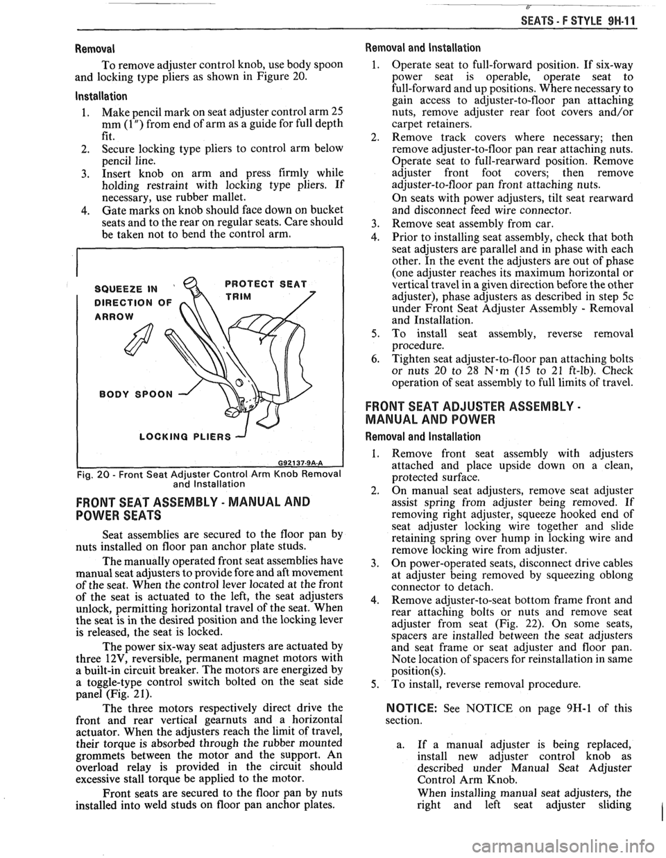
To remove adjuster control knob, use body spoon
and locking type pliers as shown in Figure 20.
lnstallation
1. Make
pencil mark on seat adjuster control arm 25
mm
(1 ") from end of arm as a guide for full depth
fit.
2. Secure locking type pliers
to control arm below
pencil line.
3. Insert knob on arm and press firmly while
holding restraint with locking type pliers. If
necessary, use rubber mallet.
4. Gate marks on knob should face down on bucket
seats and to the rear on regular seats. Care should
be taken not to bend the control arm.
SQUEEZE IN '
DIRECTION OF
ARROW PROTECT
SEAT
TRIM
BODY
SPOON \\.,
I
LOCKING PLIERS -J
I
Fig. 20 - Front Seat Adjuster Control Arm Knob Removal
and lnstallation
FRONT SEAT ASSEMBLY - MANUAL AND
POWER SEATS
Seat assemblies are secured to the floor pan by
nuts installed on floor pan anchor plate studs.
The manually operated front seat assemblies have
manual seat adjusters to provide fore and aft movement
of the seat. When the control lever located at the front
of the seat is actuated to the left, the seat adjusters
unlock, permitting horizontal travel of the seat. When
the seat is in the desired position and the locking lever
is released, the seat is locked.
The power six-way seat adjusters are actuated by
three
12V, reversible, permanent magnet motors with
a built-in circuit breaker. The motors are energized by
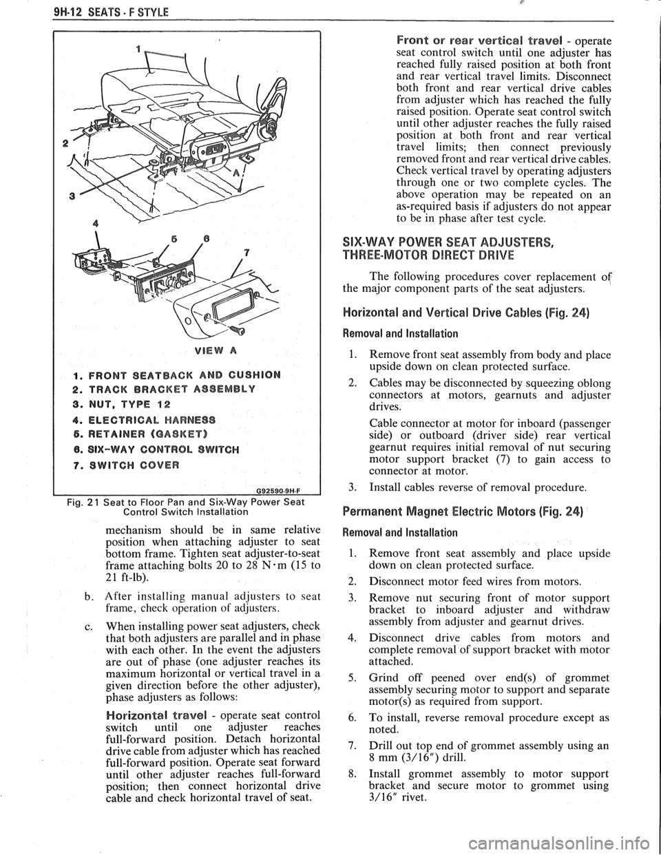
a toggle-type control switch bolted on the seat side
panel (Fig. 2
1).
The three motors respectively direct drive the
front and rear vertical
gearnuts and a horizontal
actuator. When the adjusters reach the limit of travel,
their torque is absorbed through the rubber mounted
grommets between the motor and the support. An
overload relay is provided in the circuit should
excessive stall torque be applied to the motor.
Front seats are secured to the floor pan by nuts
installed into weld studs on floor pan anchor plates.
Removal and lnstallation
1. Operate seat to full-forward position. If six-way
power seat
is operable, operate seat to
full-forward and up positions. Where necessary to
gain access to adjuster-to-floor pan attaching
nuts, remove adjuster rear foot covers and/or
carpet retainers.
2. Remove track covers where necessary; then
remove adjuster-to-floor pan rear attaching nuts.
Operate seat to full-rearward position. Remove
adjuster front foot covers; then remove
adjuster-to-floor pan front attaching nuts.
On seats with power adjusters, tilt seat rearward
and disconnect feed wire connector.
3. Remove seat assembly from car.
4. Prior to installing seat assembly, check that both
seat adjusters are parallel and in phase with each
other. In the event the adjusters are out of phase
(one adjuster reaches its maximum horizontal or
vertical travel in a given direction before the other
adjuster), phase adjusters as described in step
5c
under Front Seat Adjuster Assembly - Removal
and Installation.
5. To install seat assembly, reverse removal
procedure.
6. Tighten seat adjuster-to-floor pan attaching bolts
or nuts 20 to 28
N.m (15 to 21 ft-lb). Check
operation of seat assembly to full limits of travel.
FRONT SEAT ADJUSTER ASSEMBLY -
MANUAL AND POWER
Removal and lnstallation
1. Remove front seat assembly with adjusters
attached and place upside down on a clean,
protected surface.
2. On manual seat adjusters, remove seat adjuster
assist spring from adjuster being removed. If
removing right adjuster, squeeze
hooked end of
seat adjuster locking wire together and slide
retaining spring over hump in locking wire and
remove locking wire from adjuster.
3. On power-operated seats, disconnect drive cables
at adjuster being removed by squeezing oblong
connector to detach.
4. Remove adjuster-to-seat bottom frame front and
rear attaching bolts or nuts and remove seat
adjuster from seat (Fig. 22). On some seats,
spacers are installed between the seat adjusters
and seat frame or seat adjuster and floor pan.
Note location of spacers for reinstallation in same
position(s).
5. To install, reverse removal procedure.
NOTICE: See NOTICE on page 9H-1 of this
section.
a. If a manual adjuster is being replaced,
install new adjuster control knob as
described under Manual Seat Adjuster
Control Arm Knob.
When installing manual seat adjusters, the
right and left seat adjuster sliding
I
Page 1795 of 1825
91.1-1 2 SEATS - F STYLE
VIEW A
1. FRONT SEATBACK AND GUSHION
2. TRACK BRACKET AS8EMBLY
8. NUT, TYPE $2
4. ELECTRICAL HARNESS
5. RETAINER (GASKET)
8. SIX-WAY CONTROL SWITCH
7. SWITCH COVER
Fig. 2 1 Seat to Floor Pan and Six-Way Power Seat
Control Switch Installation
mechanism should be in same relative
position when attaching adjuster to seat
bottom frame. Tighten seat adjuster-to-seat
frame attaching bolts
20 to 28 N.m (15 to
21 ft-lb).
b. After installing manual adjusters to seat
frame, check operation of adjusters.
c. When installing power seat adjusters, check
that both adjusters are parallel and in phase
with each other. In the event the adjusters
are out of phase (one adjuster reaches its
maximum horizontal or vertical travel in a
given direction before the other adjuster),
phase adjusters as follows:
Horizonta! travel - operate seat control
switch until one adjuster reaches
full-forward position. Detach horizontal
drive cable from adjuster which has reached
full-forward position. Operate seat forward
until other adjuster reaches full-forward
position; then connect horizontal drive
cable and check horizontal travel of seat.
Front or rear vertical travel - operate
seat control switch until one adjuster has
reached fully raised position at both front
and rear vertical travel limits. Disconnect
both front and rear vertical drive cables
from adjuster which has reached the fully
raised position. Operate seat control switch
until other adjuster reaches the fully raised
position at both front and rear vertical
travel limits; then connect previously
removed front and rear vertical drive cables.
Check vertical travel by operating adjusters
through one or two complete cycles. The
above operation may be repeated on an
as-required basis if adjusters do not appear
to be in phase after test cycle.
SIX-WAY POWER SEAT ADJUSTERS,
THREE-MOTOR DIRECT DRIVE
The following procedures cover replacement of
the major component parts of the seat adjusters.
Horizontal and Vertical Drive Cables (Fig. 24)
Removal and Installation
1.
Remove front seat assembly from body and place
upside down on clean protected surface.
2. Cables may be disconnected by squeezing oblong
connectors at motors,
gearnuts and adjuster
drives.
Cable connector at motor for inboard (passenger
side) or outboard (driver side) rear vertical
gearnut requires initial removal of nut securing
motor support bracket (7) to gain access to
connector at motor.
3. Install cables reverse of removal procedure.
Permanent Magnet Electric Motors (Fig. 24)
Removal and Installation
1. Remove front seat assembly and place upside
down on clean protected surface.
2. Disconnect motor feed wires from motors.
3. Remove nut securing front of motor support
bracket to inboard adjuster and withdraw
assembly from adjuster and
gearnut drives.
4. Disconnect drive cables from motors and
complete removal of support bracket with motor
attached.
5. Grind off peened over
end(s) of grommet
assembly securing motor to support and separate
motor(s) as required from support.
6. To install, reverse removal procedure except as
noted.
7. Drill out top end of grommet assembly using an
8 mm
(3/16") drill.
8. Install grommet assembly to motor support
bracket and secure motor to grommet using
3/16" rivet.