1988 PONTIAC FIERO oil level
[x] Cancel search: oil levelPage 415 of 1825
BB.4 ENGINE COOLING
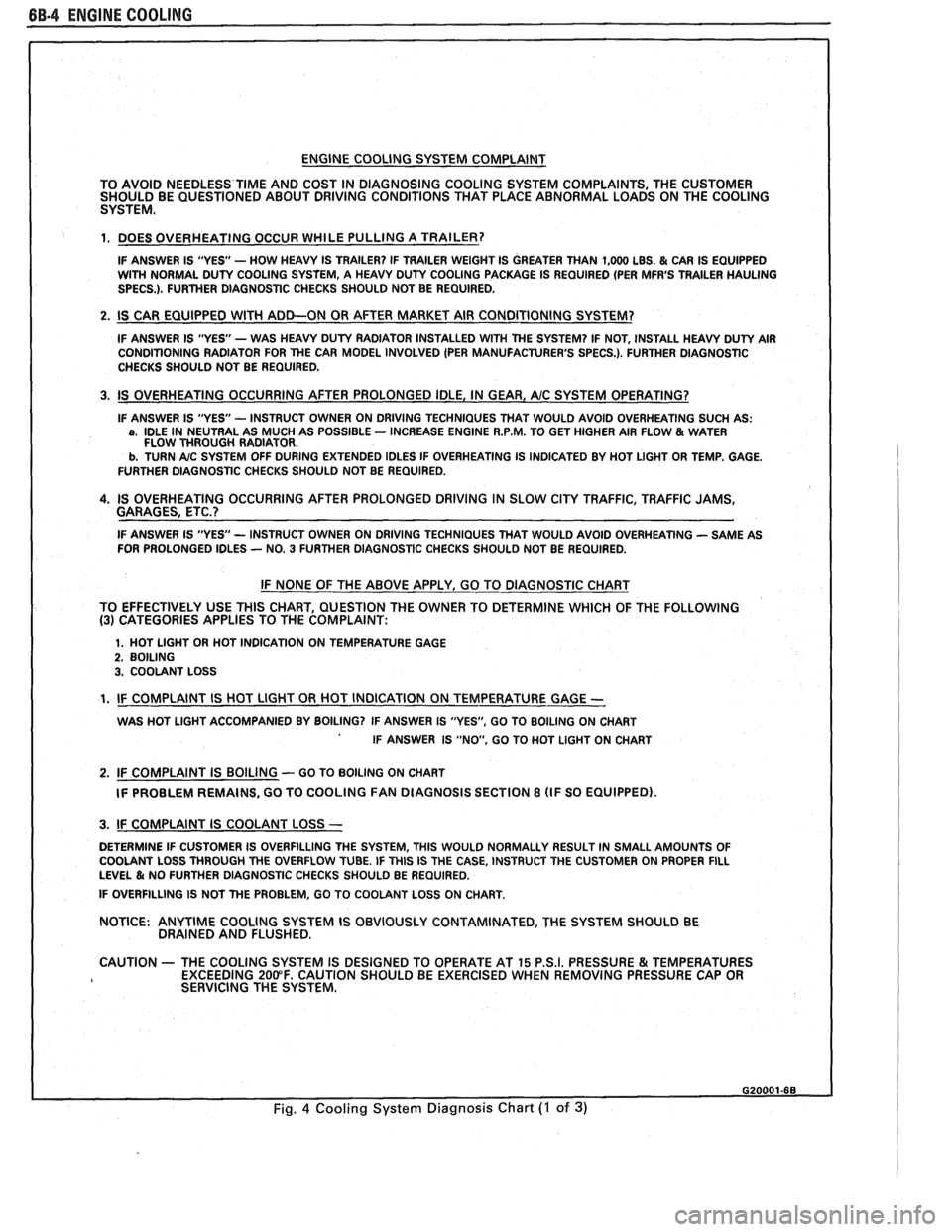
ENGINE COOLING SYSTEM COMPLAINT
TO AVOID NEEDLESS
TIME AND COST IN DIAGNOSING COOLING SYSTEM COMPLAINTS, THE CUSTOMER
SHOULD BE QUESTIONED ABOUT DRIVING CONDITIONS THAT PLACE ABNORMAL LOADS ON THE COOLING
SYSTEM.
1. DOES OVERHEATING OCCUR WHILE PULLING A TRAILER?
IF ANSWER IS "YES'- HOW HEAVY IS TRAILER? IF TRAILER WEIGHT IS GREATER THAN 1,000 LBS. & CAR IS EQUIPPED
WITH NORMAL DUTY COOLING SYSTEM, A HEAVY DUTY COOLING PACKAGE IS REQUIRED (PER MFR'S TRAILER HAULING
SPECS.). FURTHER DIAGNOSTIC CHECKS SHOULD NOT BE REQUIRED.
2. IS CAR EQUIPPED WlTH ADD-ON OR AFTER MARKET AIR CONDITIONING SYSTEM?
IF ANSWER IS "YES"- WAS HEAVY DUTY RADIATOR INSTALLED WITH THE SYSTEM? IF NOT, INSTALL HEAVY DUTY AIR
CONDITIONING RADIATOR FOR THE CAR MODEL INVOLVED (PER MANUFACTURER'S SPECS.). FURTHER DlAGNOSTlC
CHECKS SHOULD NOT BE REQUIRED.
3. IS OVERHEATING OCCURRING AFTER PROLONGED IDLE, IN GEAR, AIC SYSTEM OPERATING?
IF ANSWER IS "YES - INSTRUCT OWNER ON DRIVING TECHNIQUES THAT WOULD AVOID OVERHEATING SUCH AS: a, IDLE IN NEUTRAL AS MUCH AS POSSIBLE - INCREASE ENGINE R.P.M. TO GET HIGHER AIR FLOW & WATER
FLOW THROUGH RADIATOR.
b. TURN A/C SYSTEM OFF DURING EXTENDED IDLES IF OVERHEATING IS INDICATED BY HOT LIGHT OR TEMP. GAGE.
FURTHER DIAGNOSTIC CHECKS SHOULD NOT BE REQUIRED.
4. IS OVERHEATING OCCURRING AFTER PROLONGED DRIVING IN SLOW CITY TRAFFIC, TRAFFIC JAMS,
GARAGES, ETC.?
IF ANSWER IS "YES - INSTRUCT OWNER ON DRIVING TECHNIQUES THAT WOULD AVOID OVERHEATING - SAME AS
FOR PROLONGED IDLES - NO. 3 FURTHER DIAGNOSTIC CHECKS SHOULD NOT BE REQUIRED.
IF NONE OF THE ABOVE APPLY, GO TO DIAGNOSTIC CHART
TO EFFECTIVELY USE THlS CHART, QUESTION THE OWNER TO DETERMINE WHICH OF THE FOLLOWING
(3) CATEGORIES APPLIES TO THE COMPLAINT:
1. HOT LlGHT OR HOT INDICATION ON TEMPERATURE GAGE 2. BOILING 3. COOLANT LOSS
1. IF COMPLAINT IS HOT LlGHT OR HOT INDICATION ON TEMPERATURE GAGE -
WAS HOT LlGHT ACCOMPANIED BY BOILING? IF ANSWER IS "YES", GO TO BOILING ON CHART
IF ANSWER IS "NO, GO TO HOT LlGHT ON CHART
2. IF COMPLAINT IS BOILING - GO TO BOILING ON CHART
IF PROBLEM REMAINS, GO TO COOLING
FAN DIAGNOSIS SECTION 8 (IF SO EQUIPPED).
I 3. IF COMPLAINT IS COOLANT LOSS -
DETERMINE IF CUSTOMER IS OVERFILLING THE SYSTEM, THlS WOULD NORMALLY RESULT IN SMALL AMOUNTS OF
I COOLANT LOSS THROUGH THE OVERFLOW TUBE. IF THlS IS THE CASE, INSTRUCT THE CUSTOMER ON PROPER FILL LEVEL & NO FURTHER DIAGNOSTIC CHECKS SHOULD BE REQUIRED.
I IF OVERFILLING IS NOT THE PROBLEM, GO TO COOLANT LOSS ON CHART.
NOTICE:
ANYTIME COOLING SYSTEM IS OBVIOUSLY CONTAMINATED, THE SYSTEM SHOULD BE
DRAINED AND FLUSHED.
1 CAUTION - THE COOLING SYSTEM IS DESIGNED TO OPERATE AT 15 P.S.I. PRESSURE & TEMPERATURES
EXCEEDING 200°F. CAUTION SHOULD BE EXERCISED WHEN REMOVING PRESSURE CAP OR
I SERVICING THE SYSTEM.
Fig. 4 Cooling System Diagnosis Chart (I of 3)
Page 418 of 1825
ENGINE COOLING BB-7
NOTICE: If recommended quality antifreeze is
used, supplemental inhibitors or additives claiming
to provide increased cooling capability are not
necessary. They may be detrimental to the efficient
operation of the system, and represent an
unnecessary operating expense.
Every 12 months or 15,000 miles, the cooling
system should be serviced as follows;
1. Wash radiator cap and filler neck with clean
water.
2. Check coolant for proper level and freeze
protection.
3. Pressure test system and radiator cap for proper
pressure holding capacity, 103
kPa (15 psi). If
replacement of cap is required, use the proper cap
specified for car model.
4. Tighten hose clamps and inspect all hoses. Replace
hoses whenever cracked, swollen or otherwise
deteriorated.
5. Clean frontal area of radiator core and air
conditioning condenser.
DRAINING AND REFILLING THE COOLING
SYSTEM
Replace hoses every 24 months or 30,000 miles or
earlier if cracked, swollen or otherwise deteriorated.
Every two years or 30,000 miles, whichever first
occurs, the cooling system should be flushed and
refilled using the following recommended procedure:
1. Remove radiator cap, or thermostat housing cap
(VIN
0, J, R and U), when engine is cool by:
a. Slowly
rotating cap counterclockwise to
detent. (Do not press down while rotating.)
b. Wait until any
residual pressure (indicated
by a hissing sound) is relieved.
c. After all hissing ceases, press down on cap
while continuing to rotate
counterclockwise.
CAUTION: To avoid the danger of
being burned, do not remove radiator
cap while engine and radiator are still
hot. Scalding fluid and steam may be
blown out under pressure.
2. Remove the thermostat by using the wire handle
to lift it out of the housing (VIN
0, J, R and U).
3. With the thermostat removed, reinstall the
thermostat housing cap (VIN
0, J, R and U).
4. Open radiator drain valve and block drain plugs
to drain coolant. On VIN R and
9 (P series)
engines, open coolant pipe plugs.
5. Close valve. Reinstall drain plugs, and add
sufficient water to fill system.
6. Run engine, drain and refill the system, as
described in steps
4 and 5 a sufficient number of
times, until the drained liquid is nearly colorless.
Important
BLOCK DRIVE WHEELS, place
transmission in PARK (automatic
transmission) or NEUTRAL (manual
transmission) and set the parking brake. 7.
Allow system to drain completely. Then close
radiator drain valve tightly, and reinstall block
drain plugs.
8. Remove recovery cap leaving hoses in place.
Remove coolant recovery tank and empty of
fluid. Flush tank with clean water, drain and
reinstall.
9. Add sufficient ethylene glycol coolant, meeting
GM specification 1825-M, to provide the
required freezing and corrosion protection
- at
least 50 percent solution -37°C (-34°F). Fill
radiator to the base of the radiator fill neck and
add sufficient coolant to the recovery tank to
raise level to the "FULL" mark. Reinstall
recovery tank cap.
10. Run engine, with radiator cap or thermostat
housing cap removed, until normal operating
temperature is reached. (Radiator upper hose
becomes hot.)
11. With engine idling, add coolant until level
reaches bottom of filler neck and reinstall cap,
making certain arrows line up with overflow tube.
CAUTION: Under some conditions, the
ethylene glycol in engine coolant is
flammable. To help avoid being
burned when adding coolant, DO NOT
spill
it on the exhaust system or hat
engine parts.
It is the owner's responsibility to keep the freeze
protection at a level appropriate to the
temperatures which may occur in the area of
vehicle operation.
a. Maintain
cooling system freeze protection
at
-37°C (-34"F), to ensure protection
against corrosion and loss of coolant from
boiling, even though freezing temperatures
are not expected.
b. Add ethylene glycol base coolant that meets
GM Specification 1825-M, when coolant
additions are required because of coolant
loss, or to provide additional protection
against
freezing at temperatures lower than
-37°C (-34°F).
NOTICE: Alcohol or methanol base coolants, or
plain water, are not recommended at any time.
DRlVE BELT
NOTICE: Routine inspection of the belt may
reveal cracks in the belt ribs. These cracks will
not impair belt performance and therefore should
not be considered a problem requiring belt
replacement. However, the belt should be
replaced if belt slip occurs or if sections of the
belt ribs are missing.
A single (serpentine) belt is used to drive all
engine accessories formerly driven by multiple drive
belts. All belt driven accessories are ridgedly mounted
with belt tension maintained by a spring loaded
tensioner.
The drive belt tensioner has the ability to control
belt tension over a fairly broad range of belt lengths.
Page 425 of 1825
6B-I4 ENGINE COOLING
SMALL
586826
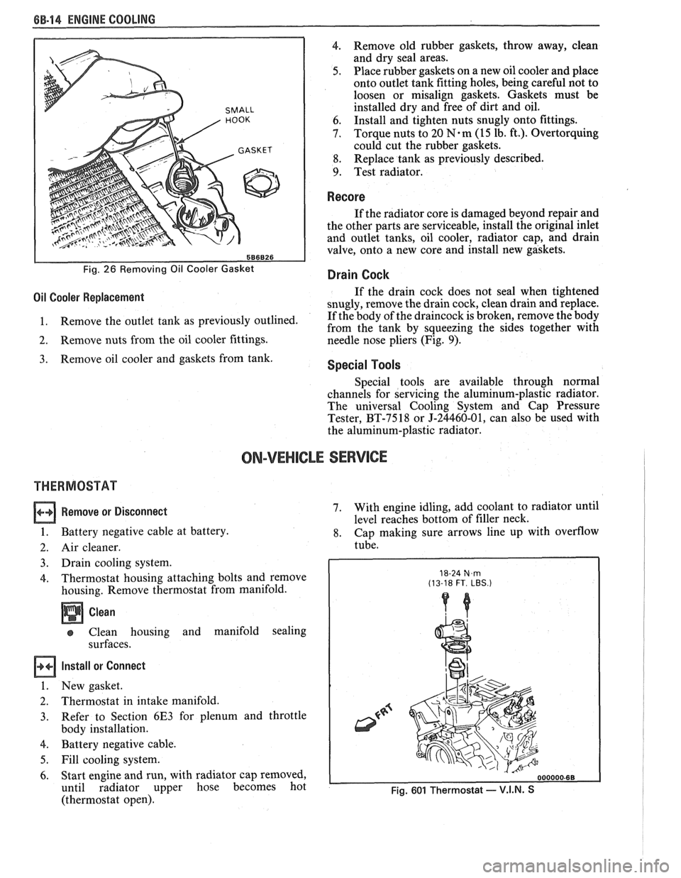
Fig. 26 Removing Oil Cooler Gasket
4. Remove old rubber gaskets, throw away, clean
and dry seal areas.
5. Place rubber gaskets on a new oil cooler and place
onto outlet tank fitting holes, being careful not to
loosen or misalign gaskets. Gaskets must be
installed dry and free of dirt and oil.
6. Install
and tighten nuts snugly onto fittings.
7. Torque nuts
to 20
N.m (15 lb. ft.). Overtorquing
could cut the rubber gaskets.
8. Replace
tank as previously described.
9. Test radiator.
Recore
If the radiator core is damaged beyond repair and
the other parts are serviceable, install the original inlet
and outlet tanks, oil cooler, radiator cap, and drain
valve, onto a new core and install new gaskets.
Drain Cock
Oil Cooler Replacement If the drain cock does not seal when tightened
snugly, remove the drain cock, clean drain and replace.
1. Remove
the outlet tank as previously outlined. If
the body of the draincock is broken, remove the body
from the tank by squeezing the sides together with
2. Remove nuts from the oil cooler fittings.
needle nose pliers (Fig. 9).
Remove oil cooler and gaskets from tank. Special Tools
Special tools are available through normal
channels for servicing the aluminum-plastic radiator.
The universal Cooling System and Cap Pressure
Tester, BT-7518 or J-24460-01, can also be used with
the aluminum-plastic radiator.
ON-VEHICLE SERVICE
THERMOSTAT
Remove or Disconnect
1. Battery negative cable at battery.
2. Air cleaner.
3. Drain cooling system.
4. Thermostat housing attaching bolts and remove
housing. Remove thermostat from manifold.
Clean
Clean housing and manifold sealing
surfaces.
Install or Connect
1. New gasket.
2. Thermostat in intake manifold.
3. Refer
to Section 6E3 for plenum and throttle
body installation.
4. Battery negative cable.
5. Fill cooling system.
6. Start engine and run, with radiator cap removed,
until radiator upper hose becomes hot
(thermostat open). 7.
With
engine idling, add coolant to radiator until
level reaches bottom of filler neck.
8. Cap making sure arrows line up with overflow
tube.
18-24 N,m (13-18 FT. LBS.)
Fig. 601 Thermostat - V.I.N. S
Page 771 of 1825
6E3-C6-2 2.8L (WIN 5) DRIVEABILITY AND EMISSIONS
When the solenoid is de-energized, the pressurized
air from the air pump is allowed to enter the decel
timing chamber. This places sufficient pressure on
the metering valve diaphragm to overcome spring
tension, closing the
valve,causing air to divert to the
silencer.
At higher engine speeds, excess air is exhausted to
the silencer through the pressure relief valve. (Figure
C6-1)
Deceleration Valve
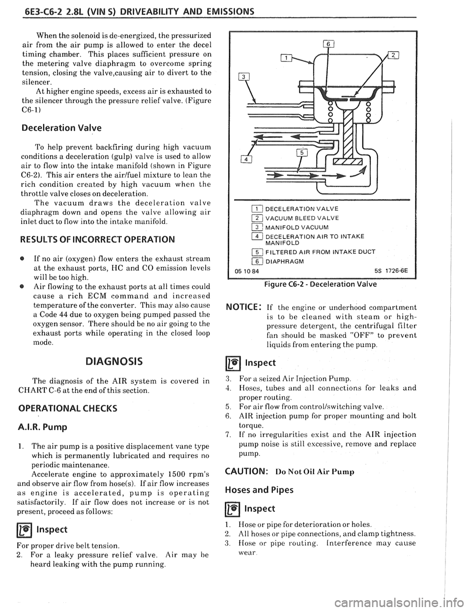
To help prevent backfiring during high vacuum
conditions a deceleration (gulp) valve is used to allow
air to flow into the intake manifold (shown in Figure
C6-2). This air enters the airlfuel mixture to lean the
rich condition created by high vacuum when the
throttle valve closes on deceleration.
The vacuum draws the deceleration valve
diaphragm down and opens the valve allowing air
inlet duct to flow into the intake manifold.
RESULTS OF INCORRECT OPERATION
@ If no air (oxygen) flow enters the exhaust stream
at the exhaust ports, HC and
CO emission levels
will be too high.
@ Air flowing to the exhaust ports at all times could
cause
a rich ECM command and increased
temperature of the converter. This may also cause
a Code
44 due to oxygen being pumped passed the
oxygen sensor. There should be no air going to the
exhaust ports while operating in the closed loop
mode.
DIAGNOSIS
The diagnosis of the AIR system is covered in
CHART C-6 at the end of this section.
OPERATIONAL CHECKS
A.I.R. Pump
1. The air pump is a positive displacement vane type
which is permanently lubricated and requires no
periodic maintenance.
Accelerate engine to approximately
1500 rpm's
and observe air flow from
hose(s). If air flow increases
as engine is accelerated, pump is operating
satisfactorily. If air flow does not increase or is not
present, proceed as follows:
Inspect
For proper drive belt tension.
2. For a leaky pressure relief valve. Air may he
heard leaking with the pump running.
DECELERATION VALVE
1 VACUUM BLEED VALVE
1 MANIFOLD VACUUM
1 DECELERATION AIR TO INTAKE
MANIFOLD
1 FILTERED AIR FROM INTAKE DUCT
/ DIAPHRAGM
05 10 84 5s 1726-6E
Figure C6-2 - Deceleration Valve
NOTICE: If the engine or underhood compartment
is to he cleaned with
steam or high-
pressure detergent, the centrifugal filter
fan should be masked "OFF7' to prevent
liquids from entering the pump.
Inspect
3. For a seized Air Injection Pump.
3. Hoses, tubes and all connections for leaks and
proper routing.
5, For air flow from controllswitching valve.
6. AIR injection pump for proper mounting and bolt
torque.
7. If no irregularities exist and the AIR injection
pump noise is still excessive, remove and replace
pump.
CAUTION: Do Not Oil Air Pump
Hoses and Pipes
Inspect
1. Hose or pipe for deterioration or holes.
2. All hoses or pipe connections, and clamp tightness.
3. Hose or pipe routing. Interference may cause
wear
Page 929 of 1825
6E3-C6-2 5.OL (VIN F) & 5.7L (VIN 8) DRIVEABILITY AND EMISSIONS
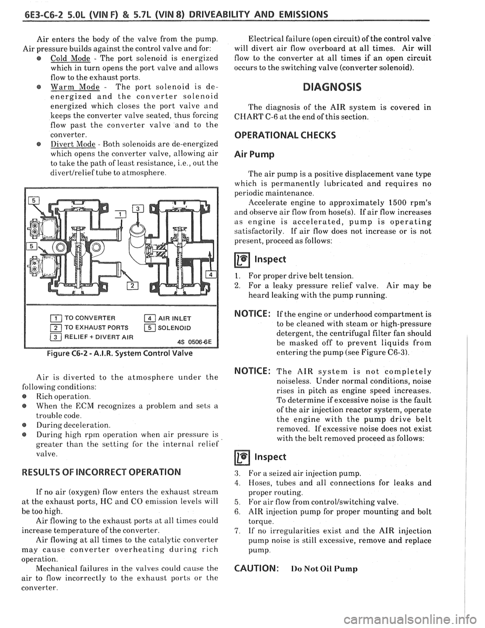
Air enters the body of the valve from the pump.
Air pressure builds against the control valve and for:
@ Cold Mode - The port solenoid is energized
which in turn opens the port valve and allows
flow to the exhaust ports.
Warm Mode
- The port solenoid is de-
energized and the converter solenoid
energized which closes the port valve and
keeps the converter valve seated, thus forcing
flow past the converter valve and to the
converter.
@ Divert Mode - Both solenoids are de-energized
which opens the converter valve, allowing air
to take the path of least resistance,
i.e., out the
divertlrelief tube to atmosphere. Electrical
failure (open circuit) of the control valve
will divert air flow overboard at all times. Air will
flow to the converter at all times if an open circuit
occurs to the switching valve (converter solenoid).
DIAGNOSIS
The diagnosis of the AIR system is covered in
CHART C-6 at the end of this section.
OPERATIONAL CHECKS
Air Pump
The air pump is a positive displacement vane type
which is permanently lubricated and requires no
periodic maintenance.
llccelerate engine to approximately 1500 rpm's
and observe air flow from hose(s). If air flow increases
as engine is accelerated, pump is operating
satisfactorily. If air flow does not increase or is not
present, proceed as follows:
Inspect
I. For proper drive belt tension.
2. For a leaky pressure relief valve. Air may be
heard leaking with the pump running.
TO CONVERTER AIR INLET
TO EXHAUST PORTS
1 SOLENOID
Figure C6-2 - A.I.R. System Control Valve
Air is diverted to the atmosphere under the
lowing conditions:
Rich operation.
When the
ECM recognizes a problem and sets a
trouble code.
@ During deceleration.
During high rprn operation when air pressure is
greater than the setting
for the internal relief
valve.
RESULTS OF INCORRECT OPERATION
If no air (oxygen) flow enters the exhaust stream
at the exhaust ports, I-IC and CO emission levels will
be too high.
Air flowing to the exhaust ports at all times could
increase temperature of the converter.
Air flowing at all times to the catalytic converter
may cause converter overheating during rich
a ion.
oper
t'
Mechanical failures in the valves could cause the
air to flow incorrectly to the exhaust ports or the
converter.
NOTICE : If the engine or underhood compartment is
to be cleaned with steam or high-pressure
detergent, the centrifugal filter fan should
be masked off to prevent liquids from
entering the pump (see Figure
C6-3).
NOTICE: The AIR system is not completely
noiseless. Under normal conditions, noise
rises in pitch as engine speed increases.
To determine if excessive noise is the fault
of the air injection reactor system, operate
the engine with the pump drive belt
removed. If excessive noise does not exist
with the belt removed proceed as follows:
a inspect
3. For a seized air injection pump.
4. Hoses, tubes and all connections for leaks and
proper routing.
5. For air flow from control/switching valve.
6. AIR injection pump for proper mounting and bolt
torque.
7. If no irregularities exist and the AIR injection
pump noise is still excessive, remove and replace
Pump.
CAUTION: 110 Not Oil Pump
Page 973 of 1825
6E-12 DRIVEABILITY AND EMISSIONS - FUEL INJECUION
and MPH) for abbreviations used in this Section, but
all types are acceptable.
NA/F - AI WFUEL (NF RATIO)
A.I.R.
- AIR INJECTOR REACTION SYSTEM - Air
flow from pump is directed into engine exhaust
manifold
and/or converter to reduce exhaust
emissions.
ALDL - ASSEMBLY LINE DIAGNOSTIC LINK - Used
at assembly to evaluate Computer Command Control,
and for service to flash the "Service Engine Soon"
light
if there are trouble codes. It also is used by
"Scan" tools to obtain ECM serial data.
BARO - BAROMETRIC ABSOLUTE PRESSURE
SENSOR
- Reads atmospheric pressure.
B + - Battery Positive Terminal (12 Volts) or
system voltage with the engine running
(approximately 13.8
v.)
CALPAK - A device used with fuel injection to
allow fuel delivery in the event of a PROM or ECM
malfunction.
CALIBRATOR - (PROM) - An electronic component
that can be
specifically programmed to meet engine
operating requirements for a
specific vehicle model.
It plugs into the Engine Control Module
(ECM).
CCC - COMPUTER COMMAND CONTROL - has an
electronic control module to control airlfuel and
emission systems.
CLCC - CLOSED LOOP CARBURETOR CONTROL -
Used to describe oxygen sensor to ECM to MIC
solenoid circuit operation.
C3I - Computer Controlled Coil Ignition. Produces
the ignition spark without the aid of an ignition
distributor.
CCP - CONTROLLED CANISTER PURGE - ECM
controlled solenoid valve that permits manifold
vacuum to purge the evaporative emissions from the
charcoal canister.
CID - CUBIC INCH DISPLACEMENT - Used to
describe engine size.
UL OR ULOOP - "CLOSED LOOP" - Describes ECM
fuel control when using oxygen sensor information.
COOLANT TEMPERATURE SENSOR - Device that
senses the engine coolant temperature, and passes
that information to the engine control module.
CONV. - CATALYTIC CONVERTER, THREE-WAY -
EXHAUST CONVERTER. Containing platinum and
palladium to speed up conversion of
HC and CO, and
rhodium to accelerate conversion of NO,.
CO - CARBON MONOXIDE - One of the pollutants
found in engine exhaust.
6V - CRANKCASE VENTlhaflON - Prevents fumes
in crankcase from passing into the atmosphere, by
drawing them into the intake manifold and burning
them in the the combustion process.
DIAGNOSTIC CODE - Pair of numbers obtained
from flashing "Service Engine Soon" light or
displaying on a "Scan" tool. This code can be used to
determine the system malfunction.
DIAGNOSTIC TERM. - Lead of ALDL Connector
which is grounded to get a Trouble Code.
It is
grounded with the engine running to enter the "Field
Service Mode".
DIS - Direct Ignition System. Produces the
ignition spark without the aid of an ignition
distributor.
DVM (10 Meg.) - Digital Voltmeter with 10 Million
ohms resistance
- used for measurement in electronic
systems.
DWELL - The amount of time (recorded on a dwell
meter in degrees of crankshaft rotation) that current
passes through a closed switch; for example, ignition
contact points or internal switch in an electronic
control module.
EAC - ELECTRIC AIR CONTROL - Used on A.I.R.
system to direct air flow to air switching valve or to
atmosphere.
EAS - ELECTRIC AIR SWITCHING - used to direct air
flow to catalytic converter or exhaust ports of the
engine.
ECM - ENGINE CONTROL MODULE (ELECTRONIC) -
A metal case (located in passenger compartment)
containing electronic circuitry which electrically
controls and monitors airlfuel and emission systems
on computer command control, and turns
"ON" the
"Service Engine Soon" light when a malfunction
occurs in the system.
EFI - ELECTRONIC FUEL INJECTION - Computer
Command Control using throttle body fuel injection.
EGR - EXHAUST GAP REClRCUbATlON - Method of
reducing NO, emission levels by causing exhaust gas
to be added to airlfuel mixture in combustion
chamber, thus cooling combustion.
EECS - EVAPORATIVE EMISSIONS CONTROL
SYSTEM
- Used to prevent gasoline vapors in the fuel
tank from entering the atmosphere.
EFE - EARLY FUEL EVAPORATION - Method of
warming the intake manifold during cold engine
operation. Provides efficient airlfuel mixing.
ENERGIZEIDE-ENERGIZE - When current is passed
through a coil (energized) such as the canister purge
solenoid, the plunger is pulled into the solenoid.
Page 975 of 1825
6E-14 DRIVEABILITY AND EMISSIONS - FUEL INJECTION
N.O. - NORMALLY OPEN - State of relay contacts
or solenoid plunger when no voltage
is applied.
NOx - NITROGEN, OXIDES OF - One of the
pollutants found in engine exhaust.
O2 - OXYGEN (Sensor) - Monitors the oxygen
content of the exhaust system and generates a voltage
signal to the ECM.
OIL or OILOOP - OPEN LOOP - Describes ECM fuel
control without use of oxygen sensor information.
OUTPUT - Result of a function typically controlled
by the ECM.
OXYGEN SENSOR. EXHAUST - Device that detects
the amount of oxygen
(02) in the exhaust stream.
P.A.1.R - PULSE AIR INJECTION REACTOR system -
pulsed air directed into engine to reduce exhaust
emissions.
PCV - POSITIVE CRANKCASE VENTILATION -
Prevent fumes in crankcase from passing into
atmosphere.
PFI - PORT FUEL INJECTION
PIN
- PARWNEUTWL
PORT - EXHAUST OR INTAKE PORT
PROM
- PROGRAMABLE READ ONLY MEMORY-
an electronic term used to describe the engine
calibration unit
.
RPM - REVOLUTIONS PER MINUTE - A measure of
rotational speed.
RVB - REAR VACUUM BMKE - is used to control
choke operation during cold engine conditions.
SELF-DIAGNOSTIC CODE - The ECM can detect
malfunctions in the system.
If a malfunction occurs,
the ECM turns on the "Service Engine Soon" light.
A
diagnostic code can be obtained from the ECM
through the "Service Engine Soon" light, or by use of a
"Scan" tool. This code will indicate the area of the
malfunction.
SES - SERVICE ENGINE SOON LIGHT - Lights when
a malfunction occurs in Computer Command Control
system.
TACH - TACHOMETER
TBI
- THROTTLE BODY INJECTION (Unit) - is
controlled by the ECM to supply precise airlfuel
mixture into the intake manifold.
TCC - TWNSMISSION I TRANSAXLE CONVERTER
CLUTCH
- ECM controlled solenoid in transmission
which positively couples the transmission to the
engine.
THERMAC - THERMOSTATIC AIR CLEANER -
provides preheated air to intake manifold to provide
better driveability when engine
is cold.
TPS - THROnLE POSITION SENSOR - Device that
tells the ECM the throttle position.
TVS - THERMAL VACUUM SWITCH - Used to
control vacuum in relationship to engine temperature.
V - VOLT
V-6 - SIX CYLINDER ENGINE - Two banks of
cylinders, arranged in a
"V".
V-8 - EIGHT CYLINDER ENGINE - Two banks of
cylinders, arranged in a
"V".
VACUUM - Negative pressure; less than
atmospheric pressure.
VACUUM, MANIFOLD - Vacuum source in
manifold below throttle plate.
VACUUM, PORTED - A vacuum source above I (atmospheric side ) of closed throttle plate. , I
WAC SENSOR - Abbreviation for differential
pressure sensor which is a
vacuum sensor.
VIN - VEHICLE IDENTIFIUTION NUMBER. 1
VSS - VEHICLE SPEED SENSOR - Sensor which
sends vehicle speed information to the ECM.
WASTECATE - A means of controlling the amount
of boost available for a Turbo charged engine.
WOT- WIDE OPEN THROPTLE. I
WIRING HARNESS SERVICE I
The ECM wire harness electrically connects the
ECM to the various solenoids, switches, and sensors in
vehicle engine compartment. The ECM is located
inside the vehicle passenger compartment.
Most connectors in the engine compartment are
protected against moisture and dirt which could create
oxidation and deposits on the terminals. This
protection is important because of the very low voltage
and current levels found in the electronic system. The
connectors have a lock which secures the male and
female terminals together. A secondary lock holds the
seal and terminal into the connector.
GENERAL
Molded-on connectors (like Metri-Pack) require
complete replacement of the connector. This means
splicing a new connector assembly into the harness.
Page 992 of 1825
HYDRAULIC DIAGNOSIS 700434-3
- The first to second gear shift point
- The second to third gear shift point
MANUAL SECOND (2)
2. With vehicle stopped, place gear selector in
"Second" (2) and accelerate to observe:
- The first to second gear shift point
3. Accelerate to 25 MPH (40 KPH) and observe:
- That a second to third gear shift does not
occur
- That TCC does not engage
MANUAL FIRST (I)
1. With vehicle stopped, place gear selector in
"First" (1) and accelerate to 15 MPH (24
KPH)
and observe:
- That no uoshift occurs
- That TCC does
REVERSE
1. With
vehicle stopped, place gear selector in
"Reverse" (R) and slowly accelerate to observe
reverse gear operation.
All possible throttle positions and corresponding
MPH shift point information has not been
provided.
TRANSMISSION PRESSURE CHECK
PROCEDURE
Inspect
e Fluid level
e TV cable adjustment
e Manual linkage
e Engine mechanical, emissions, electrical and fuel
delivery systems
not engage
Install or Connect (Figure 3)
a Oil pressure gage
a Tachometer