1988 PONTIAC FIERO clock
[x] Cancel search: clockPage 418 of 1825
ENGINE COOLING BB-7
NOTICE: If recommended quality antifreeze is
used, supplemental inhibitors or additives claiming
to provide increased cooling capability are not
necessary. They may be detrimental to the efficient
operation of the system, and represent an
unnecessary operating expense.
Every 12 months or 15,000 miles, the cooling
system should be serviced as follows;
1. Wash radiator cap and filler neck with clean
water.
2. Check coolant for proper level and freeze
protection.
3. Pressure test system and radiator cap for proper
pressure holding capacity, 103
kPa (15 psi). If
replacement of cap is required, use the proper cap
specified for car model.
4. Tighten hose clamps and inspect all hoses. Replace
hoses whenever cracked, swollen or otherwise
deteriorated.
5. Clean frontal area of radiator core and air
conditioning condenser.
DRAINING AND REFILLING THE COOLING
SYSTEM
Replace hoses every 24 months or 30,000 miles or
earlier if cracked, swollen or otherwise deteriorated.
Every two years or 30,000 miles, whichever first
occurs, the cooling system should be flushed and
refilled using the following recommended procedure:
1. Remove radiator cap, or thermostat housing cap
(VIN
0, J, R and U), when engine is cool by:
a. Slowly
rotating cap counterclockwise to
detent. (Do not press down while rotating.)
b. Wait until any
residual pressure (indicated
by a hissing sound) is relieved.
c. After all hissing ceases, press down on cap
while continuing to rotate
counterclockwise.
CAUTION: To avoid the danger of
being burned, do not remove radiator
cap while engine and radiator are still
hot. Scalding fluid and steam may be
blown out under pressure.
2. Remove the thermostat by using the wire handle
to lift it out of the housing (VIN
0, J, R and U).
3. With the thermostat removed, reinstall the
thermostat housing cap (VIN
0, J, R and U).
4. Open radiator drain valve and block drain plugs
to drain coolant. On VIN R and
9 (P series)
engines, open coolant pipe plugs.
5. Close valve. Reinstall drain plugs, and add
sufficient water to fill system.
6. Run engine, drain and refill the system, as
described in steps
4 and 5 a sufficient number of
times, until the drained liquid is nearly colorless.
Important
BLOCK DRIVE WHEELS, place
transmission in PARK (automatic
transmission) or NEUTRAL (manual
transmission) and set the parking brake. 7.
Allow system to drain completely. Then close
radiator drain valve tightly, and reinstall block
drain plugs.
8. Remove recovery cap leaving hoses in place.
Remove coolant recovery tank and empty of
fluid. Flush tank with clean water, drain and
reinstall.
9. Add sufficient ethylene glycol coolant, meeting
GM specification 1825-M, to provide the
required freezing and corrosion protection
- at
least 50 percent solution -37°C (-34°F). Fill
radiator to the base of the radiator fill neck and
add sufficient coolant to the recovery tank to
raise level to the "FULL" mark. Reinstall
recovery tank cap.
10. Run engine, with radiator cap or thermostat
housing cap removed, until normal operating
temperature is reached. (Radiator upper hose
becomes hot.)
11. With engine idling, add coolant until level
reaches bottom of filler neck and reinstall cap,
making certain arrows line up with overflow tube.
CAUTION: Under some conditions, the
ethylene glycol in engine coolant is
flammable. To help avoid being
burned when adding coolant, DO NOT
spill
it on the exhaust system or hat
engine parts.
It is the owner's responsibility to keep the freeze
protection at a level appropriate to the
temperatures which may occur in the area of
vehicle operation.
a. Maintain
cooling system freeze protection
at
-37°C (-34"F), to ensure protection
against corrosion and loss of coolant from
boiling, even though freezing temperatures
are not expected.
b. Add ethylene glycol base coolant that meets
GM Specification 1825-M, when coolant
additions are required because of coolant
loss, or to provide additional protection
against
freezing at temperatures lower than
-37°C (-34°F).
NOTICE: Alcohol or methanol base coolants, or
plain water, are not recommended at any time.
DRlVE BELT
NOTICE: Routine inspection of the belt may
reveal cracks in the belt ribs. These cracks will
not impair belt performance and therefore should
not be considered a problem requiring belt
replacement. However, the belt should be
replaced if belt slip occurs or if sections of the
belt ribs are missing.
A single (serpentine) belt is used to drive all
engine accessories formerly driven by multiple drive
belts. All belt driven accessories are ridgedly mounted
with belt tension maintained by a spring loaded
tensioner.
The drive belt tensioner has the ability to control
belt tension over a fairly broad range of belt lengths.
Page 434 of 1825
ENGINE FUEL 6C.3
a Fuel feed and return pipes are secured to the
underbody with clamps and screw assemblies.
The pipes should be inspected occasionally for
leaks, kinks or dents.
e Follow the same routing as the original pipe.
e Pipes must be properly secured to the frame to
prevent chafing. A minimum of 6 mm
(1/4")
clearance must be maintained around a pipe to
prevent contact and chafing.
MPFl Fuel Pipes
Due to the fact that fuel pipes are under high
pressure, these systems require special consideration for service.
Many feed and return pipes use screw couplings
with
"0" Rings. Any time these fittings are loosened
to service or replace components, ensure that:
a A backup wrench is used while loosening and
tightening the fitting.
e Check all "0" rings at fitting locations (if
applicable) for cuts or any damage and replace
any that appear worn or damaged.
e Use correct torque when tightening fittings.
If pipes are replaced always use original
equipment parts, or parts that meet GM
specifications.
Fuel and Vapor Hoses
NOTICE: Fuel and vapor hoses are specially
manufactured. If replacement becomes necessary,
it is important to use only replacement hoses
meeting GM Specification 6163-M. These hoses
are identified with the words "Fluoroelastomer"
on them. Hoses not so marked could cause early
failure, or fail to meet emission standards.
e Do not use rubber hose within 4" of any part of
the exhaust system, or within
10" of the catalytic
converter.
FUEL PUMP
The electric fuel pump is in the fuel tank. The
tank has an outlet for a vapor return system. Any vapor
which forms is returned to the fuel tank along with hot
fuel through a separate line. This greatly reduces any
possibility of vapor lock by keeping cool fuel from the
tank constantly circulating through the fuel pump.
FUEL PUMP RELAY
To control fuel pump operation, a fuel pump
relay is used.
When the ignition switch is turned to "RUN"
position, the fuel pump relay activates the electric fuel
pump for
1.5 to 2.0 seconds to prime the injector(s). If
the ECM does not receive reference pulses from the
distributor after this time, the ECM signals the relay
to turn off the fuel pump. The relay will once again
activate the fuel pump when the
ECM receives
distributor reference pulses.
Fuel Filter
CAUTION: To reduce the risk of fire
and personal injury, it is necessary
to
relieve the fuel system pressure
before servicing fuel system
components. (See Fuel System
Pressure Relief.)
The inline filters can be found on the rear
crossmember of the vehicle. Always use a backup
wrench any time that the fuel filter is removed or
installed. Also make sure that a good
"0" Ring is used
at all screw couple locations. Torque on fittings is
30
N-m (22 lb. ft.).
FUEL TANK
The fuel tank is usually located under the rear of
the vehicle and a number of shapes and sizes are used
depending on the application.
The tank is held in place by two metal straps,
hinged (with a bolt through the hinge) and secured at
the opposite end with a nut and bolt assembly.
Anti-squeak pieces are used on top of the tank to
reduce rattles and other annoying noises.
The fuel tank, cap and lines should be inspected
for road damage, whch could cause leakage. Inspect
fuel cap for correct sealing and indications of physical
damage. Replace any damaged or malfunctioning
parts.
Before attempting service of any type on the fuel
tank, always
(1) remove negative battery cable from
battery, (2) place "no smoking" signs near work areas,
(3) be sure to have C02 fire extinguisher handy, (4)
wear safety glasses and
(5) siphon or pump fuel into an
explosion proof container.
Fuel Filler Gap
The fuel tank filler neck is equipped with a
screw-type cap. The threaded part of the cap requires
several turns counterclockwise to remove. The long
threaded area is designed to allow any remaining fuel
tank pressure to escape while the cap is being removed.
A built-in torque-limiting device prevents
overtightening. To install, turn the cap clockwise until
a clicking noise is heard. This signals that the correct
torque has been reached and the cap is fully seated.
N OTI G E: If a fuel filler cap requires replacement,
use only a cap with the same features. Failure to
use the correct cap can result in a serious
malfunction of the system.
Available on some models is an electric locking
fuel filler cap. Information on this option will be found
in Section
9E.
FUEL TANK FILLER NECK
To help prevent refueling with leaded gasoline,
the fuel filler neck on gasoline engine cars has a built-in
restrictor and deflector. The opening in the restrictor
will only admit the smaller unleaded gas nozzle spout,
which must be fully inserted to bypass the deflector.
Attempted refueling with a leaded gas nozzle or failure
Page 456 of 1825
CRANKING SYSTEM 882-5
Corning 33 Medium or equivalent, on the shaft
underneath the overrunning clutch assembly.
2. Avoid excessive lubrication.
STARTER
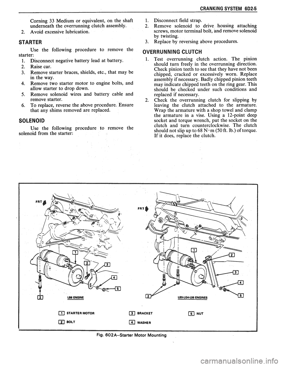
Use the following procedure to remove the
starter:
1. Disconnect negative battery lead at battery.
2. Raise car.
3. Remove starter braces, shields, etc., that may be
in the way.
4. Remove two starter motor to engine bolts, and
allow starter to drop down.
5. Remove solenoid wires and battery cable and
remove starter.
6. To replace, reverse the above procedure. Ensure
that any shims removed are replaced.
SOLENOID
Use the following procedure to remove the
solenoid from the starter:
1. Disconnect field strap.
2. Remove solenoid to drive housing attaching
screws, motor terminal bolt, and remove solenoid
by twisting.
3. Replace by reversing above procedures.
OVERRUNNING CLUTCH
1. Test overrunning clutch action. The pinion
should turn freely in the overrunning direction.
Check pinion teeth to see that they have not been
chipped, cracked or excessively worn. Replace
assembly if necessary. Badly chipped pinion teeth
may indicate chipped teeth on the ring gear. This
should be checked under such conditions and
replaced if necessary.
2. Check the overrunning clutch for slipping by
leaving the clutch attached to the armature.
Wrap the armature with a shop towel and clamp
the armature in a vise. Using a 12-point deep
socket and torque wrench, put the socket on the
clutch and turn counterclockwise. The clutch
should not slip up to
68 N-m (50 ft. lb.) of torque.
If it does, replace the clutch.
h LB8 ENGINE
a STARTER MOTOR
BOLT
FRT
BRACKET NUT
WASHER
Fig. 602A--Starter Motor Mounting
Page 473 of 1825
684.4 IGNITION SYSTEM
a spark plug wire from a spark plug, twist the 4. Do not wipe grease from module, or distributor
boot on the spark plug and pull
on the boot to base,
if same module is to be replaced.
remove the wire, or use a special tool designed to
remove spark plug boots.
Install or Connect
Remove or Disconnect
1. Ignition switch battery feed wire and tachometer
lead (if equipped) from distributor cap. Also
release the coil connectors from the cap. (DO
NOT use a screwdriver or tool to release the
locking tabs.)
2. Distributor cap by turning four screws
counterclockwise. Move cap out of the way.
3. Four-terminal ECM harness from distributor.
4. If necessary, remove secondary wires from cap,
release wiring harness latches and remove wiring
harness retainer. The spark plug wire numbers
are indicated on the retainer.
5. Distributor clamp screw and hold-down clamp.
6. Note position of rotor, then pull distributor up
until rotor just stops turning counterclockwise
and again note position of rotor.
To insure correct timing of the distributor,
the distributor must be INSTALLED with
the rotor correctly positioned as noted.
If the engine was accidentally cranked after the
distributor was removed, the following procedure can
be used for installing:
1. Remove No. 1 spark plug.
2. Place finger over No. 1 spark plug hole and crank
engine slowly until compression is felt.
3. Align timing mark on pulley to "0" on engine
timing indicator.
4. Turn rotor to point between No. 1 and No. 8
spark plug towers on distributor cap on V8
engines, between No. 1 and No. 6 on V6 engines,
and No.
1 and No. 4 on 4 cylinder engines.
5. Install distributor and connect ignition feed wire.
6. Install distributor cap and spark plug wires.
7. Check engine timing (see Set Ignition Timing).
Install or Connect
1. Insert distributor, positioning rotor as removed.
2. Distributor hold-down clamp and screw.
3. Wiring harness retainer and secondary wires, if
removed.
4. ECM harness connector.
5. Distributor cap.
6. Coil connectors.
7. Battery wire and tachometer lead, if equipped.
Module
It is not necessary to remove the distributor from
car.
Remove or Disconnect
1. Distributor cap and rotor.
2. Two module attaching screws, and lift module
UP. 3. Leads from module. (Observe color code on leads
as these cannot be interchanged.)
NOTICE: If a new module is to be installed, a
package of silicone grease will be included with it.
Spread the grease on the metal face of the module
and on the distributor base where the module
seats. This grease is necessary for module cooling.
1. Module.
2. Module leads (observe color code).
3. Attaching screws to module.
4. Rotor.
5. Cap.
Pick-Up Coil
1. Remove distributor from car and follow
instructions in Unit Repair, as applicable.
Rotor
Fig. 1
1. Remove distributor cap.
2. The rotor is retained by two screws and is
provided with a slot which fits over a square lug,
,
so that the rotor can be installed in only one
position.
Integral Ignition Coil
Fig. I
Remove or Disconnect
1. Distributor cap.
2. Three coil cover attaching screws, and lift off
cover.
3. Coil attaching screws and lift ignition coil and
leads from cap.
Install or Connect I
1. Coil and attaching screws.
2. Coil leads.
3. Coil cover and attaching screws.
Capacitor
Fig. 1
The capacitor is part of the coil wire harness
assembly. Since the capacitor is used only for radio
noise suppression, it will seldom need replacement.
Remove or Disconnect I
1. Distributor cap and rotor.
2. Capacitor attaching screw and unplug connector
from module. It may help to loosen the module.
Install or Connect I
1. Plug into module.
2. Capacitor and hold-down screw (be sure ground
lead is under screw).
Page 750 of 1825
DRIVEABILITY AND EMISSIONS 2.8L (VIN S) 6E3-CZ-15
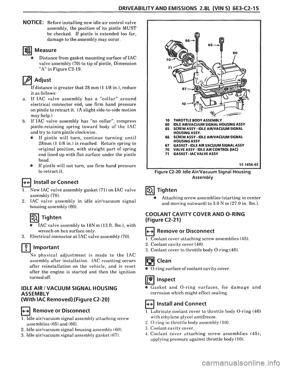
NOTICE: Before instal ling new idle air control valve
assembly, the position of its pintle
MUST
be checked. If pintle is extended too far,
damage to the assembly may occur.
Measure
@ Distance from gasket mounting surface of IAC
valve assembly
(70) to tip of pintle, Dimension
"A" in Figure
C2-19.
Adjust
If distance is greater that 28 mm (1 118 in.), reduce -
it as follows:
a. If
IAC valve assembly has
a "collar" around
electrical connector end, use firm hand pressure
on pintle to retract it. (A slight side-to-side motion
may help.)
b. If IAC valve assembly has "no collar", compress
pintle-retaining spring toward body of the IAC
and try to turn pintle clockwise.
@ If pintle will turn, continue turning until
28mm
(1 118 in.) is reached. Return spring to
original position, with straight part of spring
end lined up with flat surface under the pintle
head.
@ If pintle will not turn, use firm hand pressure
to retract it.
Install or Connect
1. New IAC valve assembly gasket (71) on IAC valve
assembly
(70).
2. IAC valve assembly in idle airlvacuum signal
housing assembly
(60).
Tighten
IAC valve assembly to 18N.m (13 ft. Ibs.), with
wrench on hex surface only.
3. Electrical connector at IAC valve assembly (70).
Important
No physical adjustment is made to the IAC
assembly after installation.
IAC resetting occurs
after reinstallation on the vehicle, and is reset
after the engine is started and then the ignition
turned off.
IDLE AIR / VACUUM SIGNAL HOUSING
ASSEMBLY
(With
IAC Removed) (Figure C2-20)
Remove or Disconnect
1. Idle airlvacuurn signal assembly attaching screw
assemblies
(65) and (66).
2. Idle airlvacuum signal housing assembly (60).
3. Idle airlvacuum signal assembly gasket (67).
10 THROTTLE BODY ASSEMBLY
60 IDLE AIWVACUUM SIGNAL
HOUSING ASSY
65 SCREW ASSY - IDLE AIWVACUUM SIGNAL
HOUSING ASSY.
66 SCREW
ASSY
- IDLE AIWVACUUM SIGNAL
HOUSING ASSY
67 GASKET - IDLE AIR VACUUM SIGNAL ASSY 70 VALVE ASSY - IDLE AIR CONTROL (IAC) 71 GASKET - IAC VALVE ASSY
Figure C2-20 Idle AirIVacuum Signal Housing
Assembly
Tighten
@ Attaching screw assemblies (starting in center
and
moving outward) to 3.0 N.m (27.0 in. Ibs.).
COOLANT CAVITY COVER AND O-RING
(Figure
C2-21)
Remove or Disconnect
1. Coolant cover attaching. screw assemblies (45).
2. Coolant cavity cover (40).
3. Coolant cover to throttle body O-ring (46).
Inspect
@ Gasket and O-ring surfaces, for damage and
corrosion which might effect sealing.
Install and Connect
1. Lubricate coolant cover to throttle body O-ring (46)
with ethylene glycol antifreeze.
2. O-ring in throttle body assembly (10).
:3. Coolant cavity cover.
4. Coolant cover attaching screw assemblies (451,
applying pressure against throttle body (1 0).
Page 900 of 1825
DRIVEABILITY AND EMISSIONS 5.OL (VIN F) & 5.7b (VIN 8) 6E3-CZ-13
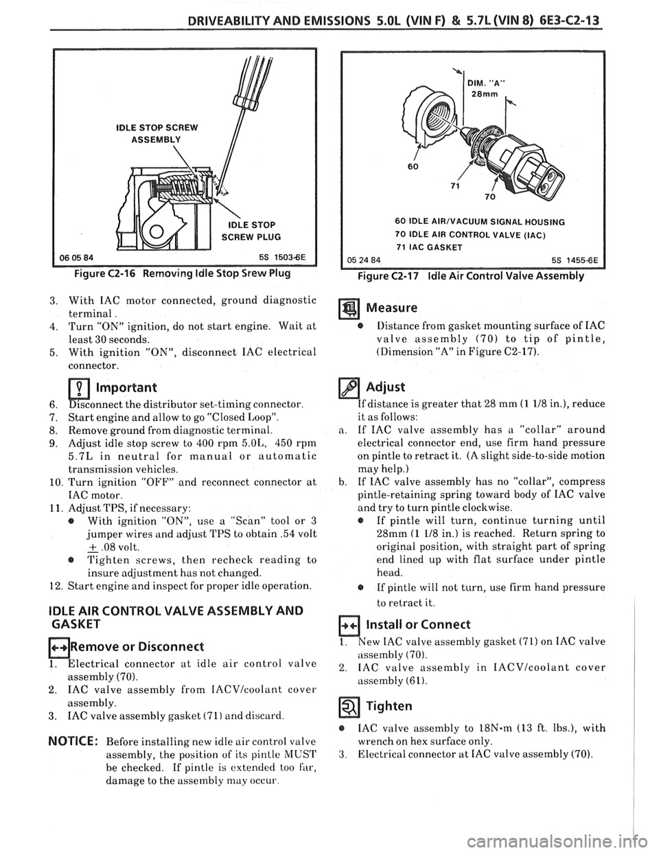
IDLE STOP SCREW
ASSEMBLY
IDLE STOP
SCREW PLUG
Figure C2-16 Removing Idle Stop Srew Plug
60 IDLE AIR/VACUUM SIGNAL HOUSING
70 IDLE AIR CONTROL VALVE (IAC)
71 IAC GASKET
Figure C2-17 Idle Air Control Valve Assembly
3. With IAC motor connected, ground diagnostic
terminal. Measure
4. Turn "ON" ignition, do not start engine. Wait at @ Distance from gasket mounting surface of IAC
least 30 seconds. valve assembly
(70) to tip of pintle,
5. With ignition
"ON", disconnect IAC electrical (Dimension
"A" in Figure C2-17).
connector.
Important
6. Disconnect
the distributor set-timing connector.
7. Start
engine and allow to go "Closed Loop".
8. Remove
ground from diagnostic terminal.
9. Adjust idle stop screw to 400 rpm 5.01,, 450 rpm
5.7L in neutral for manual or automatic
transmission vehicles.
10. Turn ignition "OFF" and reconnect connector at
IAC motor.
11. Adjust TPS, if necessary:
@ With ignition "ON", use a "Scan" tool or 3
jumper wires and adjust TPS to obtain .54 volt
+ .08 volt. - @ Tighten screws, then recheck reading to
insure adjustment has not changed.
12. Start engine and inspect for proper idle operation.
IDLE AIR CONTROL VALVE ASSEMBLY AND
CASKET
ORemove or Disconnect
1. Electrical connector at idle air control valve
assembly (70).
2. IAC valve assembly from IACVIcoolant cover
assembly.
3. IAC valve assembly gasket (71) and discard.
NOTICE: Before installing new idle air control valve
assembly, the position of its
pinlle MUST
be checked. If pintle is extended too far,
damage to the assembly
may occur
Adjust
If distance is greater that 28 mm (1 118 in.), reduce
it as follows:
a. If IAC valve assembly has a "collar" around
electrical connector end, use firm hand pressure
on pintle to retract it. (A slight side-to-side motion
may help.)
b. If
IAC valve assembly has no "collar", compress
pintle-retaining spring toward body of IAC valve
and try to turn pintle clockwise.
@ If pintle will turn, continue turning until
28mm
(1 118 in.) is reached. Return spring to
original position, with straight part of spring
end lined up with flat surface under pintle
head.
@ If pintle will not turn, use firm hand pressure
to retract it.
Install or Connect
1. New IAC valve assembly gasket (71) on IAC valve
assembly
(70).
2. IAC valve assembly in IACVIcoolant cover
assembly (61).
Tighten
IAC valve assembly to 18N.m (13 ft. Ibs.), with
wrench on hex surface only.
3. Electrical connector at IAC valve assembly (70).
Page 1050 of 1825
TORQUE CONVERTER CLUTCH (TCC)
DIAGNOSIS
To properly diagnose the Torque Converter
Clutch (TCC) system, perform all electrical
testing first and then the hydraulic testing. Refer
to the Torque Converter Section
6E2-C8 for
additional information.
The TCC is applied by fluid pressure which is
controlled by a solenoid located inside the Automatic
Transmission assembly. The solenoid is energized or
released by making or breaking an electrical circuit
through a combination of switches and sensors.
TCC Electrical Diagnosis
e For electrical diagnosis of TCC, refer to the
specific vehicle section in Section
8A, Electrical
Diagnosis.
e For diagnosis of emission control related
components of TCC, Refer to the specific section
of
6E, Driveability and Emissions.
e For the diagnosis of TCC Hydraulic Controls,
refer to the Procedure and Wiring Diagrams
provided in this section.
Functional Check Procedure
rn Inspect
1. Install a tachometer
2. Operate the vehicle until proper operating
temperature is reached
3. Drive vehicle at 50-55 mph (80-88 Km/h) with
light throttle (road load)
4. Maintaining throttle lightly touch the brake
pedal and check for a slight bump when the TCC
releases and a slight increase in engine RPM.
5. Release the brake, slowly accelerate and check for
a re-apply of the converter clutch and a slight
decrease in engine RPM.
Preliminary Checking Procedure
The purpose of the preliminary checking
procedure is to isolate external (electrical) problems
from internal (electrical or mechanical) ones.
Important
e Use only a scale type ohmmeter. High impedance
type ohmmeters and those with a digital readout
will not work.
e An ALCL scanner may be used to verify the
electrical circuit. Remember, a completed circuit
does not indicate that the solenoid will apply.
e Do not bench test using an automotive type
battery. Accidentally crossed wires will damage
the internal diodes of the TCC solenoid.
HYDRAULIC DIAGNOSIS 700-R4-61
External Controls
rn Inspect
e Connect voltmeter between transmission
connector and ground.
e Turn key "ON"
e If 0 or low voltage is found, refer to Sections 6E
and 8A for electrical diagnosis.
e If 12 volts are present at the connector, refer to
the TCC hydraulic diagnosis.
TORQUE CONVERTER EVALUATION
Torque Converter Stator
The Torque Converter Stator roller clutch can
have one of two different type malfunctions:
A. Stator Assembly freewheels in both
directions.
B. Stator Assembly remains locked up at all
times.
Condition A-Poor Acceleration Low Speed
The vehicle tends to have poor acceleration from
a standstill. At speeds above 30-35 mph (50-55
km/h),
the car may act normal. If poor acceleration is noted,
it should first be determined that the exhaust system
is not blocked, the engine timing is correct and the
transmission is in first
(1st) gear when starting out.
If the engine freely accelerates to high
r.p.m. in
"NEUTRAL" (N), it can be assumed that the engine
and exhaust system are normal. Checking for poor
performance in "Drive" and Reverse will help
determine if the stator is freewheeling at all times.
Condition B-Poor Acceleration High Speed
Engine r.p.m. and car speed limited or restricted
at high speeds. Performance when accelerating from a
standstill is normal. Engine may over-heat. Visual
examination of the converter may reveal a blue color
from over-heating.
If the converter has been removed, the stator
roller clutch can be checked by inserting a finger into
the splined inner race of the roller clutch and trying to
turn the race in both directions. The inner race should
turn freely clockwise, but not turn or be very difficult
to turn counterclockwise.
The Converter Should Be Replaced If:
e Leaks externally, such as at the hub weld area.
e Converter has an imbalance which cannot be
corrected. (Refer to Converter Vibration Test
Procedure).
e Converter is contaminated with engine coolant
containing antifreeze.
The Converter Should Not Be Replaced If:
e The oil has an odor, is discolored, and there is no
evidence of metal or clutch facing particles.
e The threads in one or more of the three converter
bolt holes are damaged.
- Correct with thread insert. (Refer to Section
6A).
Page 1083 of 1825
700-R4-32 AUTOMATIC TRANSMISSION
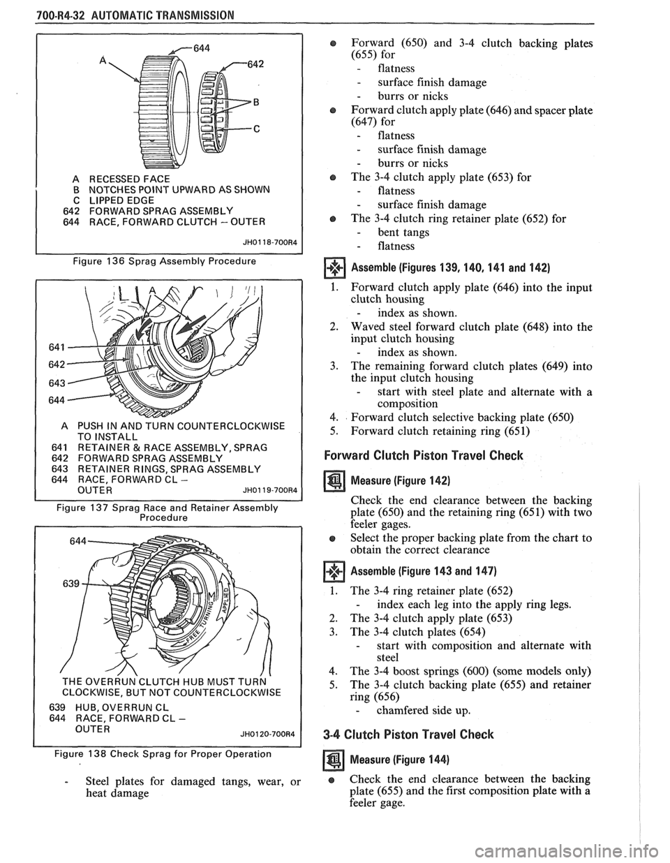
A RECESSED FACE
B NOTCHES POINT UPWARD AS SHOWN
C LIPPED EDGE
642 FORWARD SPRAG ASSEMBLY
644 RACE, FORWARD CLUTCH
- OUTER
Figure 136 Sprag Assembly Procedure
COUNTERCLOCKWISE
641
RETAlNER&RACEASSEMBLY,SPRAG 642 FORWARD SPRAG ASSEMBLY
INER RINGS, SPRAG ASSEMBLY
FORWARD CL -
Figure 137 Sprag Race and Retainer Assembly
Procedure
THE OVERRUN'CLUTCH HUB MUST TURN '
I CLOCKWISE, BUT NOT COUNTERCLOCKWISE I
639 HUB, OVERRUN CL
644 RACE, FORWARD CL - OUTER JH0120-700R4
Figure 138 Check Sprag for Proper Operation
- Steel plates for damaged tangs, wear, or
heat damage
e Forward (650) and 3-4 clutch backing plates
(655) for
- flatness
- surface finish damage
- burrs or nicks
Forward clutch apply plate (646) and spacer plate
(647) for
- flatness
- surface finish damage
- burrs or nicks
@ The 3-4 clutch apply plate (653) for
- flatness
- surface finish damage
o The 3-4 clutch ring retainer plate (652) for
- bent tangs
- flatness
Assemble (Figures 139, 140, 141 and 142)
1. Forward clutch apply plate (646) into the input
clutch housing
- index as shown.
2. Waved steel forward clutch plate (648) into the
input clutch housing
- index as shown.
3. The
remaining forward clutch plates (649) into
the input clutch housing
- start with steel plate and alternate with a
composition
4. Forward clutch selective backing plate (650)
5. Forward clutch retaining ring (651)
Forward Clutch Piston Travel Check
Measure (Figure 142)
Check the end clearance between the backing
plate (650) and the retaining ring (65 1) with two
feeler gages.
Select the proper backing plate from the chart to
obtain the correct clearance
Assemble (Figure 143 and 147)
1. The 3-4 ring retainer plate (652)
- index each leg into the apply ring legs.
2. The 3-4 clutch apply plate (653)
3. The
3-4 clutch plates (654)
- start with composition and alternate with
steel
4. The 3-4 boost springs (600) (some models only)
5. The
3-4 clutch backing plate (655) and retainer
ring (656)
- chamfered side up.
3-4 Clutch Piston Travel Check
Measure (Figure 144)
e Check the end clearance between the backing
plate (655) and the first composition plate with
a
feeler gage.