1988 PONTIAC FIERO clock
[x] Cancel search: clockPage 1122 of 1825
AUTOMATIC TMNSMISSION ON-VEHICLE SERVICE 7A1-3
e Propeller shaft oil seal worn or damaged
o Governor cover
e Line pressure pipe plug loose
@ Porous casting
3. Leak at converter end:
Converter seal damaged
- Seal lip cut. (Check converter hub for
damage.)
- Bushing moved forward and damaged
- Garter spring missing from seal
o Converter leak in weld area. (Refer to
Torque Converter.)
Porous casting (Case or pump)
4. Fluid comes out vent pipe or fill tube:
Over-filled
Water or coolant in fluid. Fluid will appear
milky.
e Case porous
e Incorrect fluid level indicator
e Plugged vent
e Drain back holes plugged
Mispositioned oil pump to case gasket (if
equipped)
Case Porosity Repair
1. Clean the leak area with solvent and air dry.
CAUTION: Epoxy adhesive may cause
skin irritations and eye damage. Read
and follow all information on the
container label as provided by the
manufacturer.
2. Mix a sufficient amount of epoxy adhesive,
# 1052533, or equivalent, following the
manufacturer's recommendations.
3. While the transmission case is hot, apply epoxy
adhesive with a clean, dry soldering acid brush.
4. Allow the epoxy adhesive to cure for three hours
before starting the engine.
5. Repeat fluid leak diagnosis procedures.
TORQUE CONVERTER CLUTCH ELECTRICAL
CONTROLS
The Torque Converter Clutch (TCC) system uses
controls that are internal as well as external to the
transmission. For internal control components of the
TCC system, refer to the I-Iydraulic Diagnosis Section
for for wiring diagrams and switch locations.
The external control components of the TCC
system include:
1. Brake Release Switch - To avoid stalling the
engine when braking, the converter clutch is
released any time the brakes are applied.
2. Electronic Control ModuOe - Receives input
signals and grounds TCC solenoid to apply clutch
when proper operating conditions are met.
3. Throttle Position Sensor - Sends throttle
position information to Electronic Control
Module.
4. Vacuum Sensor - Sends engine vacuum (load)
information to Electronic Control Module.
5. Vehicie Speed Sensor - Sends vehicle speed
information to Electronic Control Module.
6. Coolant Temperature Sensor - Sends engine
coolant temperature information to Electronic
Control Module.
TORQUE CONVERTER CLUTCH DIAGNOSIS
To properly diagnose the Torque Converter
Clutch (TCC) system perform all electrical testing first
and then the hydraulic testing. Refer to the appropriate
Driveability and Emissions Section (6E) for additional
Torque Converter Clutch Information
ON-VEHICLE SERVICE
SI-IIFT CONTROL CABLE
Remove or Disconnect (Fig. 1)
1. Negative battery cable.
2. Raise car, see Section OA.
3. Cable attachments at transmission.
4. Lower car.
5. Console, see Section
8C.
6. Cable at control lever and base.
7. Cable from floor.
install or Connect
1. Cable to floor.
2. Cable at base and control lever.
3. Console, see Section 8C.
4. Place control lever in "NEUTRAL"
5. Raise car.
6. Cable attachments at transmission.
7. Adjust cable.
8. Lower car.
9. Negative battery cable.
Adjust (Fig. 1)
1. Place control lever in "N" (Neutral).
2. Raise car, see Section 0.4.
3. Loosen cable
attachment at shift lever.
4. Rotate shift lever "clockwise" to park detent and
then back to neutral.
5. Tighten cable attachment.
15
N-m (11 lbs. ft.)
Important
Levg must be held out of "PARK" when
torquing nut.
6. Lower car.
7. Check cable adjustment by rotating control lever
thru the detents.
Remove or Disconnect (Fig. 2)
1. Negative battery cable.
2. Console, see Section 8C.
3. Cable at control lever and base.
Page 1167 of 1825
Page
Air Conditioning
Air Delivery
Electronic
.................... 68-0
Manual
....................... 65-0
Blower Controls
Electronic
.................... 66-0
Manual
....................... 63-0
Compressor Controls Electronic
.................... 67-0
Manual
....................... 64-0
................... System Check 62-0
Alarms (Audible)
Chime
......................... 77-0
Antenna(Power) ................... 151-0
Brakes
................. Warning System 41-0
................... Charging system 30-7
...................... Cigar Lighter 114-0
Circuit Breaker Details
PWR ACC Circuit
.......... Breaker 10.1.10.3.10.5.1 1.3
WDO Circuit Breaker
10.1. 10.3. 10.5. 11-4
.......... Component Location Views 201-0
Connectors (Harness Connector Faces) 202-0
el00 .......................... 202-0
............... Junction Block ((2238) 202-2
Coolant Fan
....................... 31-0
Cruise Control
..................... 34-0
Defogger
......................... 61-0
Digital Clock
...................... 150-0
Displays Digital Cluster
.................. 82-0
Coolant Temperature
........... 82-2
Page
......................... Fuel 82-3
................... Oil Pressure 82-2
.................. Speedometer 82-3
................. Door Locks (Power) 130-0
...... Driver Information Center (DIC) 86-0
Engines
... Multi-Port Fuel Injection (VIN S) 20-0
.... Multi-Port Fuel Injection (VIN 8) 23-0
.... Throttle
Body Injection (VIN E) 22-0
...... Tuned
Port Injection (VIN F) 21-0
................. Fuse Block Details 11-0
Fuse Details
........... INST LP 10.0.10.2.10.4.1 1.1
.............. TAIL 10.0.10.2.10.4.1 1.2
................ CRANK 10.0.10.2.1 0.4
.............. CTSY 10~0.10.2.10.4.1 1.2
......... STOP HAZ 10.1.10.3.10.5.1 1.3
............ RADIO 10.1.10.3.10.5.1 1.4
............ WIPER 10.1.10.3.10.5.1 1.4
.................... HATCH 10.2.1 0.4
........... HTR AlC 10.1.10.3.10.5.1 1.4
........... CIH.FAN 10.1.10.3.10.5.1 1.4
......... TURN BIU 10.1.10.3.10.5.1 1.4
............ GAGES 10.1.10.3.10.5.1 1.4
ECM-IGN
(V6 VIN S. V8 VIN F.
........ V8 VIN 8. V8 VIN E) 10.1.1 1.7
............ INJ 1 (V6 VIN S) 10.1.1 1.10
......... FPIINJ 2 (V6 VIN S) 10.1.1 1.10
... INJ 1 (V8 VIN F. V8 VIN 8) 10.3.1 1.11
FPIINJ 2 (V8 VIN F. V8 VIN 8) 10.3.1 1.11
............ CLSTR 10.1.10.3.10.5.1 1.13
............. FPIINJ 2 (V8 VIN E) 11-12
Page
Gages
................... Gages Cluster 81-0
........... Coolant Temperature 81-2
......................... Fuel 81-3
................... Oil Pressure 81-2
.................. Speedometer 81-3
................ Ground Distribution 14-0
Harness Routing Views
............. 203-0
........................... Heater 60-0
............................ Horns 40-0
Indicators
.................. Digital Cluster 82-0
................ Brake Warning 82-4
.................. Fasten Belts 82-1
...................... Hi Beam 82-1
...................... Security 82-1
............ Service Engine Soon 82-4
......................... Shift 82-5
......................... Turn 82-1
................... Gages Cluster 81-0
................ Brake Warning 81-0
.................. Fasten Belts 81-0
...................... Hi Beam 81-0
............ Service Engine Soon 81-0
......................... Shift 81-1
......................... Turn 81-0
Instrument Panel
Digital Cluster
.................. 82-0
Gages Cluster
................... 81-0
............ Interior Lights Dimming 117-0
...................... Introduction 2-0
Lights (Exterior)
........................ Back Up 112-0
...................... Fog 100.3,10 3.0
Page 1556 of 1825
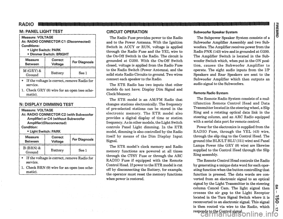
M: WNEL LIGHT TEST GlRGUlT OPERATION Subwoofer Speaker System
TOR 61 (Disconnected)
If the voltage is correct, remove Radio for
N: DISPLAY DIMMING TEST
TOW 62 (with Subwoofer
The Radio Fuse provides power to the Radio
and to the Power Antenna. With the Ignition
Switch in ACCY or RUN, voltage is applied
through the Radio Fuse and the
UEL wire to
the On-Off Switch in the Radio. The circuit is
grounded at 6200. With the On-Off Switch
closed, voltage is applied from the Radio Fuse
to the Radio Switch (Power Antenna), and the
solid state Radio Circuits to ground. Two wires
connect each speaker to the Radio.
The ETR Radio has two inputs that other
models do not have; Display Dim Signal and
ClocklMemory.
The ETR model is an AMIFM Radio that
changes stations electronically. The frequency
of pre-selected stations can be stored
in the
electronic memory. The ETR model also
provides a digital display of time or station
frequency. As in other models, the Light Switch
controls Panel Light dimming. In the
ETR
model, g is also controlled by the Radio
itself by means of the Dim Display Input
Signal.
The ETR model's clock memory and Radio
memory functions are powered at all times
through the CTSY Fuse or through the ARC
RADIO Fuse if equipped with the Remote
Control Head. If power to the ETR model is cut
off by disconnecting the Battery, for example,
the operator must reset the memory functions
when power is restored. The
Subpower Speaker
System consists of a
Subwoofer Amplifier Assembly and two Sub-
woofers. The Amplifier receives power from the
Radio PNK
(143) wire and is grounded at 6200.
The Amplifier Switch is located in the
Sub-
woofer Switch which, when put in the ON posi-
tion, causes the Subwoofer Amplifier to
operate. The eight audio inputs from the
I/P
Speakers and Rear Speakers are sent to the
Subwoofer Amplifier which then outputs an
audio signal to the Subwoofers.
Remote Radio System
The Remote Radio System consists of a mul-
tifunction Remote Control
Head and Data
Transmitter located in the steering wheel, a Slip
Ring and a rotating optical data link in the
steering
colurnn, and an ARC Radio equipped
with a serial data port for remote control.
Power for the electronics is supplied from the
RADIO Fuse, through the
YEL (43) wire,
through the slip ring to the Control Head. The
ground (the
BLKLT BLU (15 1) wire) and Pand
Larnps Power (the GRY (8) wire) are Likewise
supplied to the Control Head through the Slip
Ring assembly.
The Remote Control Head controls the Radio
by generating a unique data word for each oper-
ating function when the button controlling that
function is pressed. The data words are con-
verted from an electronic signal to an optical
signal by the Light Transmitter in the steering
column Cancel Cam. The light signal then
crosses the air gap to the Light Receptor
located in the
Turn Signal Switch where it is
reconverted to
an electronic signal. This signal
is then routed via wire to the Radio, which
responds to the Control signal.
Page 1604 of 1825
I
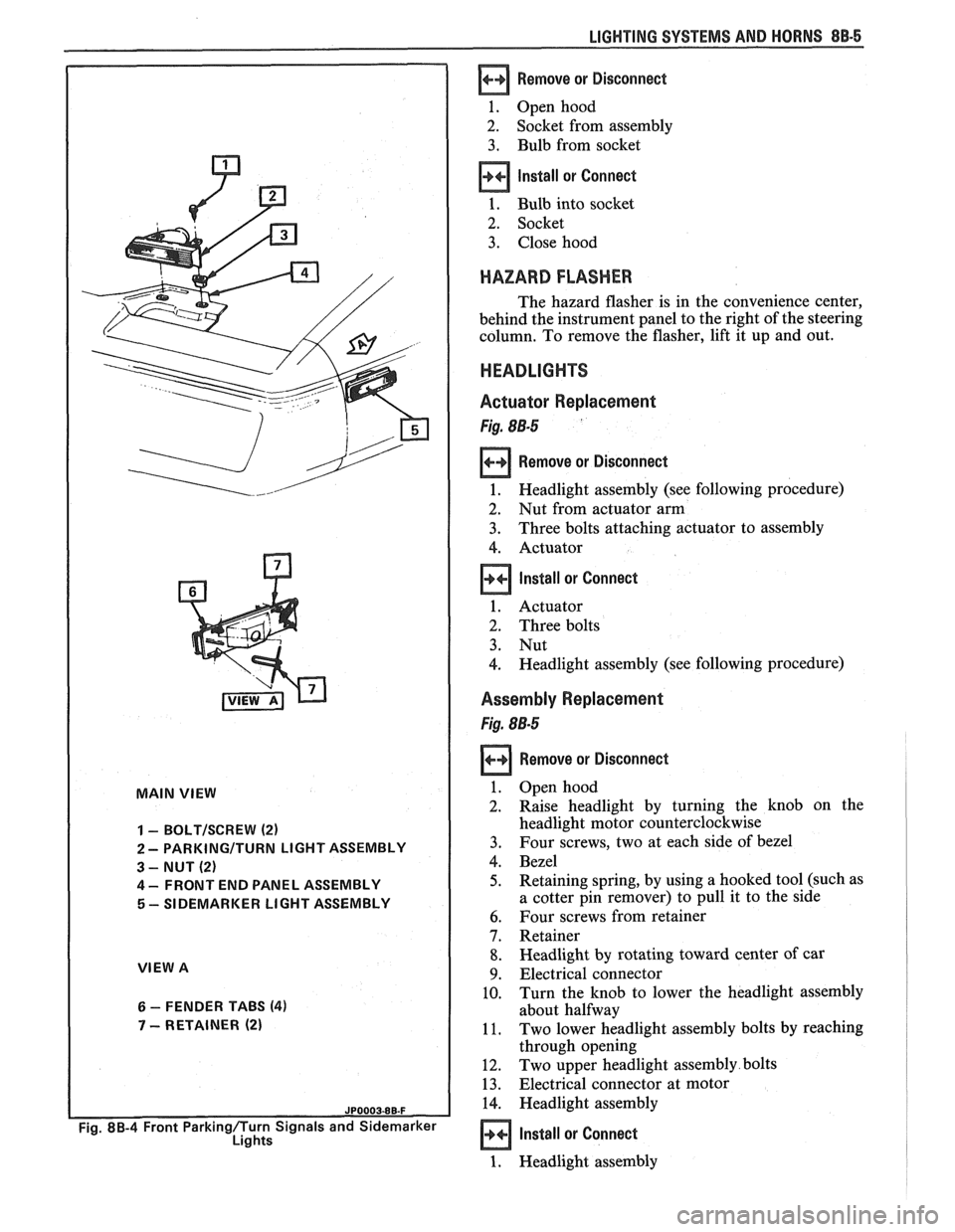
MAIN VIEW
I
1 - BOLTISCREW (2)
2 - PARKINGITURN LIGHT ASSEMBLY
3 - NUT (2)
4 - FRONT END PANEL ASSEMBLY
5 - SIDEMARKER LIGHT ASSEMBLY
VIEW A
6 - FENDER TABS (4)
7 - RETAINER (2)
Fig. 8B-4 Front Parkingflurn Signals and Sidemarker
Lights
LIGHTING SYSTEMS AND HORNS 88-5
Remove or Disconnect
1. Open hood
2. Socket from assembly
3. Bulb from socket
Install or Connect
1. Bulb into socket
2. Socket
3. Close hood
HAZARD FLASHER
The hazard flasher is in the convenience center,
behind the instrument panel to the right of the steering
column. To remove the flasher, lift it up and out.
HEADLIGHTS
Actuator Replacement
Fig. 88-5
Remove or Disconnect
1. Headlight assembly (see following procedure)
2. Nut from actuator arm
3. Three bolts attaching actuator to assembly
4. Actuator
Install or Connect
1. Actuator
2. Three bolts
3. Nut
4. Headlight assembly (see following procedure)
Assembly Replacement
Fig. 88-5
Remove or Disconnect
Open hood
Raise headlight by turning the knob on the
headlight motor counterclockwise
Four screws, two at each side of bezel
Bezel
Retaining spring, by using a hooked tool (such as
a cotter pin remover) to pull it to the side
Four screws from retainer
Retainer
Headlight by rotating toward center of car
Electrical connector
Turn the knob to lower the headlight assembly
about halfway
Two lower headlight assembly bolts by reaching
through opening
Two upper headlight assembly bolts
Electrical connector at motor
Headlight assembly
Install or Connect
1. Headlight assembly
Page 1609 of 1825
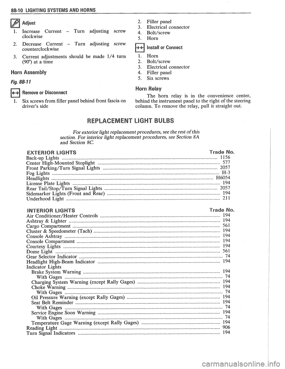
Adjust 2 . Filler panel 3 . Electrical connector
1 . Increase Current - Turn adjusting screw 4 . ~~l~/~~~~~
clockwise 5 . Horn
2 . Decrease Current . Turn adjusting screw
counterclockwise
Install or Connect
3 . Current adjustments should be made 1/4 turn
(90") at a time
Horn Assembly
Remove or Disconnect
1 . Six screws from filler panel behind front fascia on
driver's side 1
. Horn
2 . Bolt/screw
3 . Electrical connector
4
. Filler panel
5 . Six screws
Horn Relay
The horn relay is in the convenience center.
behind the instrument panel to the right of the steering
column
. To remove the relay. pull it straight out .
REPLACEMENT LIGHT BULBS
For exterior light replacement procedures. see the rest of this
section
. For interior light replacement procedures. see Section $A
and Section 8C .
EXTERIOR LIGHTS Trade No . ...................................................................................................................... Back-up Lights 1 156
Center
High-Mounted Stoplight ............................................................................................. 577
Front Barking/Turn Signal Eights ..................................................................................... 2057
Fog Lights
............................................................................................................................... H-3
Headlights ....................................................................................................................... H6054 ................................................................................................................ License Plate Lights 194
.................................................................................... Rear Tail/Stop/Turn Signal Lights 2057
Sidemarker Lights (Front and Rear) ...................................................................................... 194 ..................................................................................................................... Underhood Light 211
BNTERBOR LIGHTS Trade No .
......................................................................................... Air Conditioner/Heater Controls 194 .................................................................................................................. Ashtray & Lighter 194 .............................................................................................................. Cargo Compartment 561
................................................................................................ Cluster & Speedometer (Tach) 194 ..................................................................................................................... Console Ashtray 194 ............................................................................................................. Console Compartment 194
Courtesy Lights
..................................................................................................................... 194 ......................................................................................................................... Dome Light 561
Gear Selector Indicator
............................................................................................................ 74 .......................................................................................... Headlight High-Beam Indicator 194
Indicator Lights
..................................................................................................... Brake System Warning 194
With Gages
........................................................................................................................ 74
............................................................... Charging System Warning (except Rally Gages) 194 .................................................................................................................... Choke Warning
194
With Gages
........................................................................................................................ 74
...................................................................... Oil Pressure Warning (except Rally Gages) 194 ............................................................................................................ Seat Belt
Reminder 194
With Gages
.................................... ... ................................................................................. 74 ............................................................................................. Service Engine Soon Warning 194
With Gages
..................................................................................................................... 74 ............................................................ Temperature Gage Warning (except Rally Gages) 194
........................................................................................................................ Reading
Light 906 ............................................................................................................ Turn Signal Indicators 194
Page 1650 of 1825
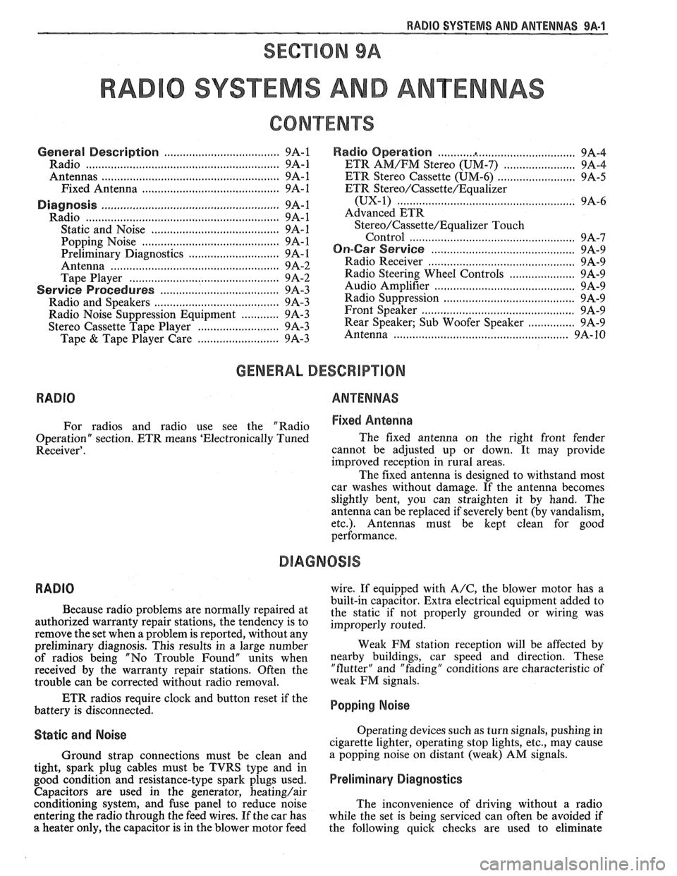
RADIO SYSTEMS AND ANTENNAS 9A-1
SECTION 9A
0 SYSTEMS AND ANTENNAS
CONTENTS
............................................. General Description .................................... 9A-1 Radio Operation 9A-4
Radio
............................................................ 9A-1 ETR AM/FM Stereo (UM-7) ....................... 9A-4
Antennas
........................................................ 9A- 1 ETR Stereo Cassette (UM-6) ......................... 9A-5
Fixed Antenna
.......................................... 9A- 1 ETR Stereo/Cassette/Eaualizer
Diagnosis ........................................................
Radio ....................... .. ................................
Static and Noise .................................... .....
........................................ Popping Noise
Preliminary Diagnostics
.............................
Antenna ................................. .. ................
Tape Player .................. .... .......................
Service Procedures ....................................
Radio and Speakers ........................... .............
Radio Noise Suppression Equipment ............
Stereo Cassette Tape Player ..........................
Tape & Tape Player Care ........................
(UX-1) ..................................................... 9A-6
Advanced ETR
Stereo/Cassette/Equalizer Touch
Control
.................................... ... .............. 9A-7
On-Car Service .............................................. 9A-9
Radio Receiver
............................................ 9A-9
Radio Steering Wheel Controls
..................... 9A-9
Audio Amplifier
........................................... 9A-9
Radio Suppression
..................................... 9A-9
Front Speaker
................................................. 9A-9
............... Rear Speaker; Sub Woofer Speaker
9A-9
Antenna
..................... .. ............................. 9A- 10
GENERAL DESCRIPUION
RADIO ANTENNAS
For radios and radio use see the "Radio Fixed Antenna
Operation" section. ETR means 'Electronically Tuned The
fixed antenna on the right front fender
Receiver'. cannot be adjusted up or down. It may provide
improved reception in rural areas.
- The fixed antenna is designed to withstand most
car washes without damage. If the antenna becomes
slightly bent, you can straighten it by hand. The
antenna can be replaced if severely bent (by vandalism,
etc.). Antennas must be kept clean for good
performance.
RADIO
Because radio problems are normally repaired at
authorized warranty repair stations, the tendency is to
remove the set when a problem is reported, without any
preliminary diagnosis. This results in a large number
of radios being "No Trouble Found" units when
received by the warranty repair stations. Often the
trouble can be corrected without radio removal. wire.
If equipped with
A/C, the blower motor has a
built-in capacitor. Extra electrical equipment added to
the static if not properly grounded or wiring was
improperly routed.
Weak
FM station reception will be affected by
nearby buildings, car speed and direction. These
"flutter" and "fading" conditions are characteristic of
weak FM signals.
ETR radios require clock and button reset if the
battery is disconnected.
Popping Noise
Static and Noise Operating devices such as turn signals, pushing in
cigarette lighter, operating stop lights, etc., may cause
Ground strap connections must be clean and
a popping noise on distant (weak) AM signals.
tight, spark plug cables must be TVRS type and in
good condition and resistance-type spark plugs used.
Preliminary Diagnostics
Capacitors are used in the generator, heating/air
conditioning system, and fuse panel to reduce noise
The inconvenience of driving without a radio
entering the radio through the feed wires. If the car has
while the set is being serviced can often be avoided if
a heater only, the capacitor is in the blower motor feed
the following quick checks are used to eliminate
Page 1663 of 1825
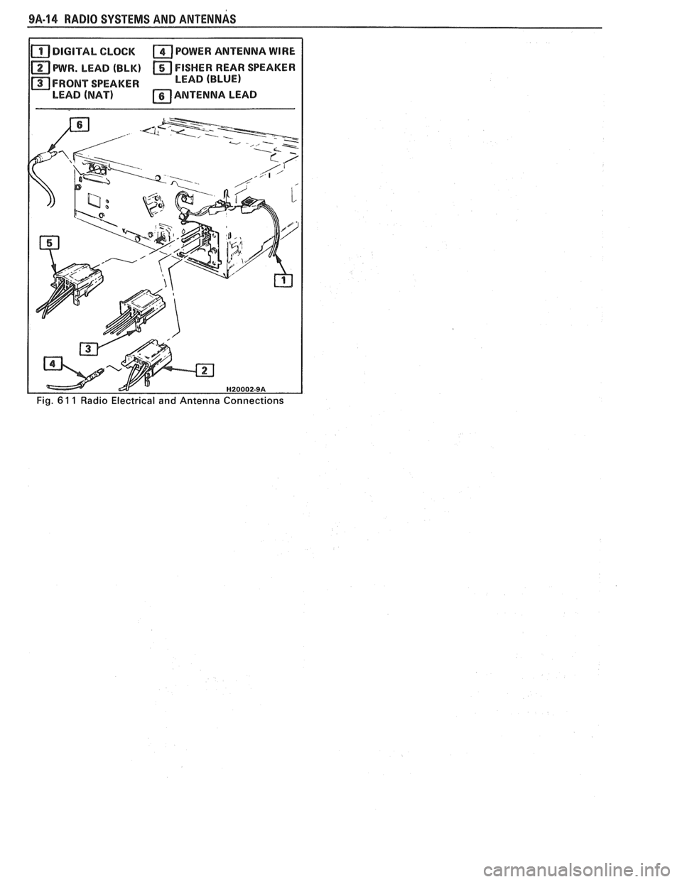
9A-14 RADIO SYSTEMS AND ANTENNAS
DIGITAL CLOCK POWER ANTENNA WIRE
PWR. LEAD (BLK) FISHER REAR SPEAKER
FRONT SPEAKER LEAD (BLUE)
LEAD
(NAT) ANTENNA LEAD
Page 1789 of 1825
9H-6 SEATS - F STYLE
3. To install head restraint, insert post into guide
and push downward to full-down position. Check
that lock spring engages and prevents head
restraint from being removed.
HEAD RESTRAINT ESCUTCHEON
ATTACHING [AND LOCK ASSEMBLY
SCREW ,
HEAD RESTRAINT
GUIDE ASSEMBLY
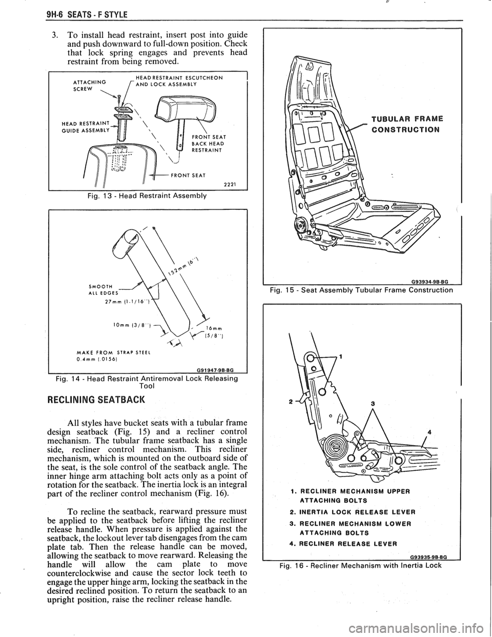
Fig. 13 - Head Restraint Assembly
MAKE FROM STRAP STEEL 0.4mm 1.01561
Fig. 14 - Head Restraint Antiremoval Lock Releasing
Tool
RECLINING SEATBACK
All styles have bucket seats with a tubular frame
design
seatback (Fig. 15) and a recliner control
mechanism. The tubular frame
seatback has a single
side, recliner control mechanism. This recliner
mechanism, which is mounted on the outboard side of
the seat, is the sole control of the
seatback angle. The
inner hinge arm attaching bolt acts only as a point of
rotation for the seatback. The inertia lock is an integral
part of the recliner control mechanism (Fig.
16).
To recline the seatback, rearward pressure must
be applied to the
seatback before lifting the recliner
release handle. When pressure is applied against the
seatback, the lockout lever tab disengages from the cam
plate tab. Then the release handle can be moved,
allowing the
seatback to move rearward. Releasing the
handle will allow the cam plate to move
counterclockwise and cause the sector lock teeth to
engage the upper hinge arm, locking the
seatback in the
desired reclined position. To return the
seatback to an
upright position, raise the recliner release handle.
Fig. 15 - Seat Assembly Tubular Frame Construction
1. RECLINER MECHANISM UPPER
ATTACHING BOLTS
2. INERTIA LOCK RELEASE LEVER
3. RECLINER MECHANISM LOWER
ATTACHING BOLTS
4. RECLINER RELEASE LEVER
G93935-96-BG
Fig. 16 - Recliner Mechanism with Inertia Lock