1988 PONTIAC FIERO check transmission fluid
[x] Cancel search: check transmission fluidPage 1101 of 1825
700.R4-50 AUTOMATIC TRANSMISSION
366
363
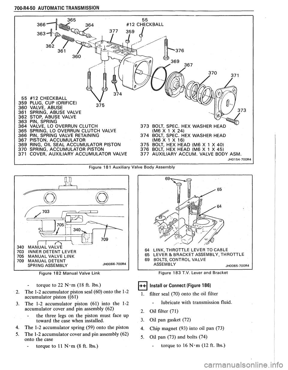
55 #12 CHECKBALL
359 PLUG, CUP (ORIFICE)
360 VALVE, ABUSE
361 SPRING, ABUSE VALVE 73
362 STOP, ABUSE VALVE
363 PIN, SPRING
364 VALVE, LO OVERRUN CLUTCH
365 SPRING, LO OVERRUN CLUTCH VALVE (M6
X
1 X 24)
366 PIN, SPRING VALVE RETAINING
374 BOLT, SPEC. HEX WASHER HEAD
367 PISTON, ACCUMULATOR (M6 X 1 X
16) 369 RING, OIL SEAL ACCUMULATOR PISTON
375 BOLT, HEX HEAD (M6 X 1 X 40)
370 SPRING, ACCUMULATOR PISTON 376 BOLT, HEX HEAD (M6 X 1 X 45) 371 COVER, AUXILIARY ACCUMULATOR VALVE 377 AUXILIARY ACCUM. VALVE BODY ASM.
JH0154-700R4
Figure 18 1 Auxiliary Valve Body Assernbly
Figure 182 Manual Valve Link
64 LINK, THROTTLE LEVER TO CABLE
65 LEVER & BRACKET ASSEMBLY, THROTTLE
69 BOLTS, CONTROL VALVE
ASSEMBLY ~H0065-700R4
Figure 183 T.V. Lever and Bracket
- torque to 22 N.m (18 ft. lbs.)
2. The
1-2 accumulator piston seal (60) onto the 1-2
accumulator piston ((61)
3. The 1-2 accumulator piston (61) into the 1-2
accumulator cover and pin assembly (62)
- the three legs on the piston must face up
toward the case when installed.
4. The 1-2 accumulator spring (59) onto the piston
5. The 1-2 accumulator cover and pin assembly (62)
onto the case
- torque to 11 N*m (8 ft. lbs.)
Install or Connect (Figure 186)
1. filter seal (70)
onto the oil filter
- lubricate with transmission fluid.
2. Oil filter (71)
3. Oil pan gasket (72)
4. Chip magnet (93) into oil pan (73)
5. Oil pan (73) and bolts (74)
- torque to 16 N.m (12 ft. Ibs.)
Page 1103 of 1825
700-R4-52 AUTOMATIC TRANSMISSION
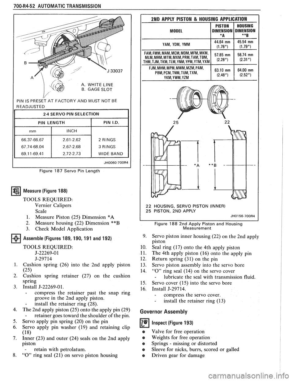
A. WHITE LINE B. GAGE SLOT
Figure 187 Servo Pin Length
Measure (Figure 188)
TOOLS REQUIRED:
Vernier Calipers
Scale
1. Measure Piston (25) Dimension
*A
2.
Measure housing (22) Dimension **B
3. Check Model Application
Assemble (Figures 189, 190, 191 and 192)
TOOLS REQUIRED:
5-22269-01
J-297 14
1. Cushion spring (26) into the 2nd apply piston
(25)
2. Cushion spring retainer (27) on the cushion
spring
3. Install J-22269-01.
- compress the retainer past the snap ring
groove in the 2nd apply piston.
- install the retainer ring (28).
4. The 2nd apply piston (25) onto the apply pin (29)
- retainer goes toward the shoulder of the pin.
5. Servo apply pin spring (20) on the pin
6. Servo apply pin washer (19) and retaining clip
(18)
7. Inner (23) and outer (24) seals on the 2nd apply
piston
- retain with petrolatum.
8. "0" ring seal (21) on servo piston housing
2ND APPLY PISTON & HOUSING APPLICATION
MODEL I DIMt!SION DIMENSION I **B I
I YAM, YOM, YMM I
MLM, MRM,MTM,MXM, PRM,TAM,TBM,
22 HOUSING, SERVO PISTON (INNER)
25 PISTON, 2ND APPLY
JH0156-700R4
Figure 188 2nd Apply Piston and Housing
Measurement
9. Servo piston inner housing (22) on the 2nd apply
piston
10. Seal ring (17) onto the 4th apply piston
11. The 4th apply piston (16) onto the apply pin
12. Return spring (31) on the pin
13. Servo piston assembly into the servo bore
14.
"0" ring seal (14) on the servo cover
- lubricate the seal with transmission fluid.
15. Servo cover (15) into the servo bore
16. Install J-297 14.
- compress the servo cover.
- install the retainer ring (13)
Governor Assembly
Inspect (Figure 193)
e Valve for free operation
e Weights for free operation
e Springs - missing or distorted
Sleeve for nicks, burrs, scored or galled
o Driven gear for damage
Page 1108 of 1825
AUTOMATIC TRANSMISSION 700-R4-57
If:
e
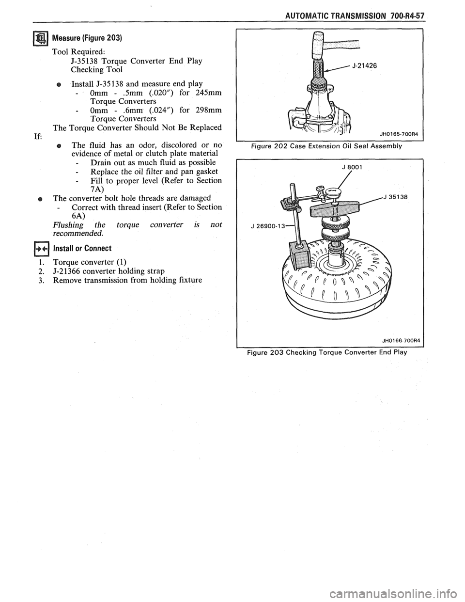
Measure (Figure 203)
Tool Required:
J-35138 Torque Converter End Play
Checking Tool
Install J-35 138 and measure end play
- Omm - .5mm (.02OU) for 245mm
Torque Converters
- Omm - .6mm (.024") for 298mm
Torque Converters
The Torque Converter Should Not Be Replaced
e The fluid has an odor, discolored or no
evidence of metal or clutch plate material
- Drain out as much fluid as possible
- Replace the oil filter and pan gasket
- Fill to proper level (Refer to Section
7A)
The converter bolt hole threads are damaged - Correct with thread insert (Refer to Section
6-4)
Flushing the torque converter is not
recommended.
Install or Connect
Torque converter (1)
J-2 1366 converter holding strap
Remove transmission from holding fixture
Figure 203 Checking Torque Converter End Play
Page 1116 of 1825
AUTOMATIC TRANSMISSION 7A-1
SECTION 7
AUTOMAT C TRANSM
CONTENTS
GENERAL INFORMATION AUTOMATIC TRANSMISSION .................................... 7A
ON VEHICLE SERVICE .................................................................................................. 7A 1
700-R4 UNIT REPAIR .................................................................................................. 700-R4
SECTION 7A
TRANSM ON GENERAL NFORMAT
CONTENTS
TRANSMISSION IDENTIFICATION NOISE AND VIBRATION
INFORMATION
..................... .. .............. 7A- I ANALYSIS .................... .... .............. 7A-3
TRANSMISSION DEFINITIONS TRANSMISSION FLUID LEVEL
Throttle Positions
.......................... .. ..... 7A-2 INFORMATION ....................................... 7A-3
Shift Conditions .................................... .... . 7A-2 TRANSMISSION FLUID LEVEL
Noise Conditions
....................................... 7A-2 CHECKING
PRELIMINARY CHECKING PROCEDURE
............................................ 7A-3
PROCEDURE
......................................... 7A-3
The information contained in this section is common to all automatic transn~issions. For on-vehicle service
procedures refer to Section
7A1. For complete Diagnosis and Unit Repair refer to the specific transrllission sections.
For vehicles sold in Canada also refer to the appropriate Canadian Service Manual Supplement for-
driveuhility
diagnosis.
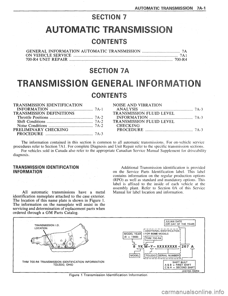
TRANSMISSION IDENTIFICATION Additional Transmibsion identification is pr-ov~dcd
INFORMATION on the Service Parts Identification label. This labcl
contains information on the regular production option
(RPO) as well as standard and mandatory options. Th14
label is affixed to the inde of each vehrcle at thc
assembly plant. Refer to Section OA of this Scrvice
All automatic transmissions have a metal Manual for label location and information.
identification nameplate attached to the case exterior.
The location of this name plate is shown in Figure
1.
The information on the nameplate will assist in the
servicing and determination of replacement parts when
ordered through a GM Parts Catalog.
r----------- I ADDITIONAL IDENTIFICATION: MODEL YEAR I FOR SOME MODELS
THM 700-R4 TRANSMISSION IDENTIFICATION INFORMATION TOLEDO, OHIO A & B = FIRST SHIFT
JH0192-700R4
Figure 1 Transmission Identification Information
Page 1118 of 1825
AUTOMATIC TRANSMISSION 7A-3
PRELIMARY CHECKING PROCEDURE
The condition of an automatic transmission not
operating properly may be influenced by one, or a
combination of the following items:
e Fluid level high/low
(Refer to Section 7A1)
e Engine performance
(Refer to Sections 6 and 6E)
T.V. cable adjustment
(Refer to Section
7A1)
e Manual linkage adjustment
(Refer to Section
7A1)
e Internal fluid leaks
(Refer to Transmission Unit Repair section)
e Electrical system
(Refer to Section 6E and 8A)
e Transmission or other mechanical component
(Refer to Transmission Unit Repair section)
e Vacuum modulator
(Refer to appropriate Hydraulic Diagnosis
Section)
NOISE AND VIBRATION ANALYSIS
A noise or vibration that is noticeable when the
vehicle is in motion, MAY NOT be the result of the
transmission.
If noise or vibration is noticeable in "Park"
(P)
and "Neutral" (N) with engine at idle, but is less
noticeable as
RPM's increase, the cause may be from
poor engine performance.
e Tires for
- Uneven wear
- Imbalance
- Mixed sizes
- Mixed radial and bias ply
(Refer to Section 3E)
e Suspension components for
- Alignment and wear
- Loose fasteners
(Refer to Section 3C)
e Engine/Transmission mounts for
- Damage
- Loose bolts
(Refer
to Sections 6A and 7A2)
e Transmission case mounting holes for:
- Missing bolts, nuts, studs
- Stripped threads
- Cracks
e Flywheel for:
- Missing or loose bolts
- Cracks
- Imbalance
(Refer to Section 6A)
e Torque converter for: - Missing or loose bolts or lugs - Missing or loose balance weights
- Imbalance
TRANSMISSION FLUID LEVEL INFORMATION
Checking fluid level, color and condition at
regular intervals will provide early diagnosis
information about the transmission. This information
may then be used to correct a condition that, if not
detected early, could result in major transmission
repairs.
When adding or changing fluid, use only
DEXRONO 11, or equivalent. Refer to Section OB of
this Service Manual for maintenance information and
servicing intervals.
Fluid level should be checked when it reaches
normal operating temperatures of
190-200°F.
(88-93°C). This temperature is reached after
approximately 15 miles (24 km) of highway
driving.
e Fluid color - Should be dark red (may be dark green)
NOTICE: Do not overfill. Overfilling will cause
foaming, loss of fluid and possible damage to the
transmission.
Inaccurate fluid level readings will result if
checked immediately after the vehicle has been
operated:
- In high abmient temperatures above 90°F
(32°C)
- At sustained high speeds
- In heavy city traffic during hot weather
- As a towing vehicle - In commercial service (taxi or police use)
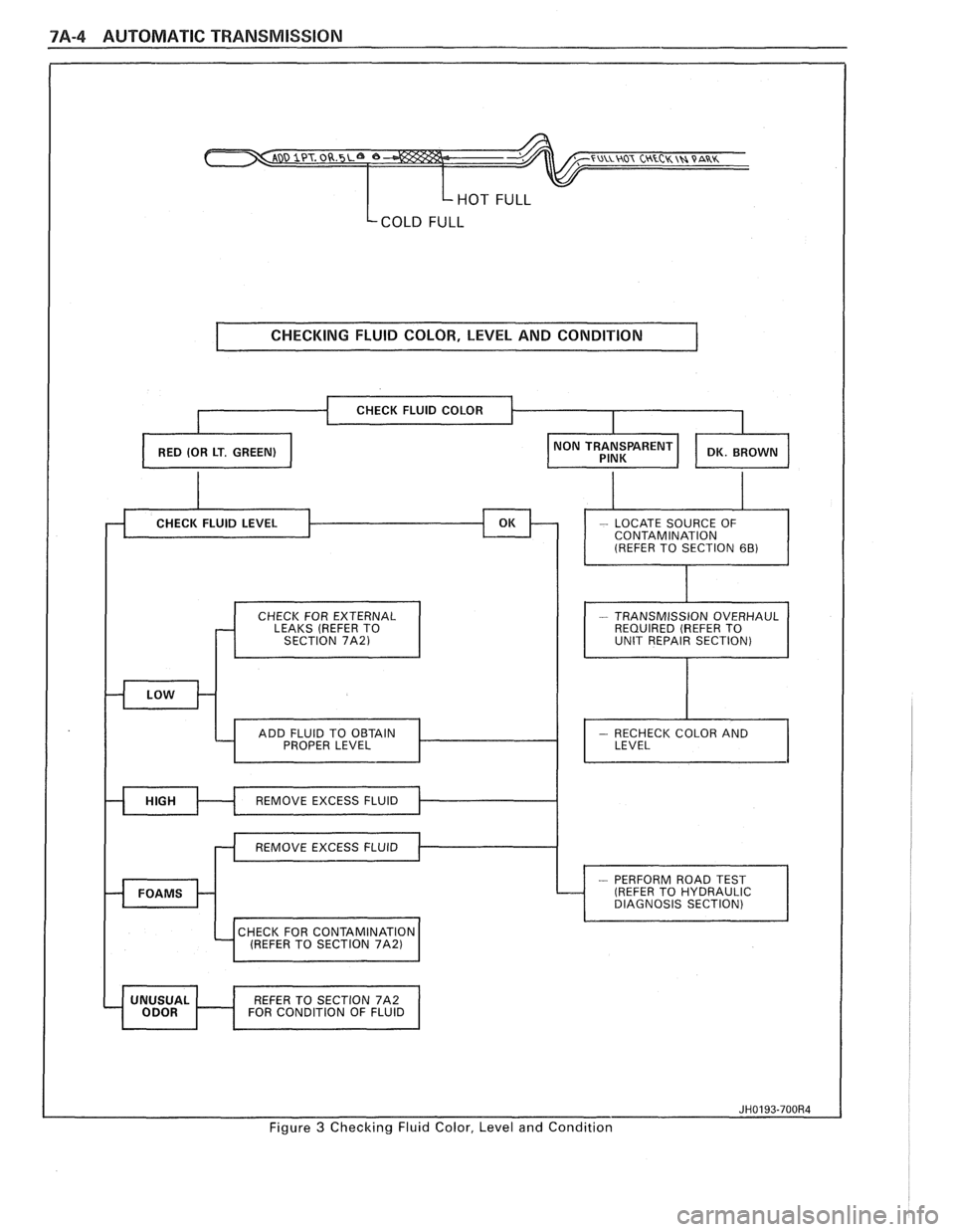
TRANSMISSION FLUID CHECKING
PROCEDURE
(Refer to Figure 3)
1. Park vehicle on level ground.
2. Apply parking
brake and block wheels.
3. Start
engine and operate vehicle for 15 minutes or
until a normal operating temperature is reached.
4. Move gear
selector through all gear positions.
5. Move
gear selector to "Park" (P).
6. Check fluid level, color and condition.
Page 1119 of 1825
7A-4 AUTOMATIC TRANSMISSION
HOT FULL
Lcom FULL
I CHECKING FLUID COLOR, LEVEL AND CONDITION 1
CHECK FOR EXTERNAL
LEAKS (REFER TO
SECTION
7A21 I I
- TRANSMISSION OVERHAUL
REQUIRED (REFER TO
UNIT REPAIR SECTION)
I
CHECK FOR CONTAMINATION 4 (REFER TO SECTION 71\21 1
REFER TO SECTION 7A2
FOR CONDITION OF FLUID I
Figure 3 Checking Fluid Color, Level and Condition
Page 1121 of 1825
7A1-2 AUTOMATIC TRANSMISSION ON-VEHICLE SERVICE
Pitting
FLEXPLATE/TORQUE CONVERTER VIBRATION
TEST PROCEDURE
1. Start engine
2. With engine at idle speed and the transmission in
"Park"
(P) or "Neutral" (N), observe vibration.
3. Shut off engine.
Remove or Disconnect
e Flexplate cover attaching bolts
s Flexplate to torque converter attaching
bolts
e Rotate torque converter 120 (1/3 turn)
Install
or Connect
e Flexplate to torque converter attaching
bolts
- Torque bolts to 47 N.m (35 Ibs. ft.)
s Flexplate cover bolts
- Torque bolts to 6 N-m (53 lbs. in.)
4. Start engine and check for vibration. Repeat this
procedure un
ti1 the best possible balance is
obtained.
NOTICE: Some engine/transmission
combinations cannot be balanced in this manner
due to limited clearances between the torque
converter bolts and engine. Be sure bolts do not
bottom out in lug nuts or the torque converter
cover could be dented and cause internal damage.
FLUID LEAK DIAGNOSIS
The cause of most external leaks can generally be
located and repaired with the transmission in the car.
METHODS FOR LOCATING LEAKS
General Method
s Verify that the leak is transmission fluid.
a Thoroughly clean the suspected leak area.
s Operate the car for about 15 miles or until normal
operating temperatures are reached.
e Park the car over clean paper or cardboard.
s Shut off engine and look for fluid spots on paper.
a Make necessary repairs.
Powder Method
e Thoroughly clean the suspected leak area with
solvent.
a Apply an aerosol type powder (foot powder) to
the suspected leak area.
s Operate the car for about 15 miles or until normal
operating temperatues are reached.
s Shut off engine.
e Inspect suspected leak area and trace the leak
path through the powder to find the source.
a Make necessary repairs.
Dye And Black Light Method
A fluid dye and black light kit is available from
various tool manufacturers.
s Follow the manufacturer's recommendations for
the amount of dye to be used.
a Detect the leak with the black light.
e Correct cause of leak.
REPAIRING THE LEAK
Once the leak has been pinpointed and traced
back to its source, the cause of the leak must be
determined in order for it to be repaired properly. If a
gasket is replaced, but the sealing flange is bent, the
new gasket will not repair the leak. The bent flange
must be repaired also. Before attempting to repair a
leak, check to be sure that the following conditions are
correct as they may cause a leak.
Gaskets
s Fluid level/pressure is too high.
e Plugged vent or drain-back holes.
s Improperly torqued fasteners or dirty/damaged
threads.
a Warped flanges or sealing surface.
e Scratches, burrs or other damage to the sealing
surface.
e Damaged or worn gasket.
e Cracking or porosity of the component.
s Improper sealant used (where applicable).
Seals
e Fluid level/pressure is too high.
a Plugged vent or drain-back holes.
s Damaged seal bore (scratched, burred or nicked).
e Damaged or worn seal.
e Improper installation.
a Cracks in component.
e Manual or output shaft surface scratched, nicked
or damaged.
a Loose or worn bearing causing excess seal wear.
Possible Points of Oil Leak
I. Transmission/Transmission oil pan :
Attaching bolts not correctly torqued
s Improperly installed or damaged gasket
s Oil pan or mounting face not flat
2, Case Leak :
@ Filler pipe "multi-lip seal" damaged or
missing
a Filler pipe bracket mislocated
s T.V. cable "multi-lip" seal missing,
damaged or improperly installed
a Governor cover or "0" ring damaged or
missing
@ Speedometer driven gear/speed sensor seal
damaged
e Manual shaft seal damaged
s Oil cooler connector fittings loose or
damaged
Page 1122 of 1825
AUTOMATIC TMNSMISSION ON-VEHICLE SERVICE 7A1-3
e Propeller shaft oil seal worn or damaged
o Governor cover
e Line pressure pipe plug loose
@ Porous casting
3. Leak at converter end:
Converter seal damaged
- Seal lip cut. (Check converter hub for
damage.)
- Bushing moved forward and damaged
- Garter spring missing from seal
o Converter leak in weld area. (Refer to
Torque Converter.)
Porous casting (Case or pump)
4. Fluid comes out vent pipe or fill tube:
Over-filled
Water or coolant in fluid. Fluid will appear
milky.
e Case porous
e Incorrect fluid level indicator
e Plugged vent
e Drain back holes plugged
Mispositioned oil pump to case gasket (if
equipped)
Case Porosity Repair
1. Clean the leak area with solvent and air dry.
CAUTION: Epoxy adhesive may cause
skin irritations and eye damage. Read
and follow all information on the
container label as provided by the
manufacturer.
2. Mix a sufficient amount of epoxy adhesive,
# 1052533, or equivalent, following the
manufacturer's recommendations.
3. While the transmission case is hot, apply epoxy
adhesive with a clean, dry soldering acid brush.
4. Allow the epoxy adhesive to cure for three hours
before starting the engine.
5. Repeat fluid leak diagnosis procedures.
TORQUE CONVERTER CLUTCH ELECTRICAL
CONTROLS
The Torque Converter Clutch (TCC) system uses
controls that are internal as well as external to the
transmission. For internal control components of the
TCC system, refer to the I-Iydraulic Diagnosis Section
for for wiring diagrams and switch locations.
The external control components of the TCC
system include:
1. Brake Release Switch - To avoid stalling the
engine when braking, the converter clutch is
released any time the brakes are applied.
2. Electronic Control ModuOe - Receives input
signals and grounds TCC solenoid to apply clutch
when proper operating conditions are met.
3. Throttle Position Sensor - Sends throttle
position information to Electronic Control
Module.
4. Vacuum Sensor - Sends engine vacuum (load)
information to Electronic Control Module.
5. Vehicie Speed Sensor - Sends vehicle speed
information to Electronic Control Module.
6. Coolant Temperature Sensor - Sends engine
coolant temperature information to Electronic
Control Module.
TORQUE CONVERTER CLUTCH DIAGNOSIS
To properly diagnose the Torque Converter
Clutch (TCC) system perform all electrical testing first
and then the hydraulic testing. Refer to the appropriate
Driveability and Emissions Section (6E) for additional
Torque Converter Clutch Information
ON-VEHICLE SERVICE
SI-IIFT CONTROL CABLE
Remove or Disconnect (Fig. 1)
1. Negative battery cable.
2. Raise car, see Section OA.
3. Cable attachments at transmission.
4. Lower car.
5. Console, see Section
8C.
6. Cable at control lever and base.
7. Cable from floor.
install or Connect
1. Cable to floor.
2. Cable at base and control lever.
3. Console, see Section 8C.
4. Place control lever in "NEUTRAL"
5. Raise car.
6. Cable attachments at transmission.
7. Adjust cable.
8. Lower car.
9. Negative battery cable.
Adjust (Fig. 1)
1. Place control lever in "N" (Neutral).
2. Raise car, see Section 0.4.
3. Loosen cable
attachment at shift lever.
4. Rotate shift lever "clockwise" to park detent and
then back to neutral.
5. Tighten cable attachment.
15
N-m (11 lbs. ft.)
Important
Levg must be held out of "PARK" when
torquing nut.
6. Lower car.
7. Check cable adjustment by rotating control lever
thru the detents.
Remove or Disconnect (Fig. 2)
1. Negative battery cable.
2. Console, see Section 8C.
3. Cable at control lever and base.