1988 PONTIAC FIERO sensor
[x] Cancel search: sensorPage 492 of 1825
DRIVEABILITY AND EMISSIONS S.OL (VIN E) 6EZ-A-1
5.OL ENGINE
DIAGNOS"FC CIRCUIT CHECK Cold Oxygen Sensor
The "Diagnostic Circuit Check" verifies the On some engines. the oxygen sensor will cool off
system is functioning correctly
. Some special after only a short period of operation at idle . This will
considerations to keep in mind while making the
put the system into "Open Loop"
. To restore "Closed
"Diagnostic Circuit Check" are:
Loop" operation. run the engine at part throttle
several minutes and accelerate from idle to part
Blocking Drive Wheels throttle a few times .
The vehicle drive wheels should always be blocked BASIC PROCEDURE
while checking the system .
If you have not reviewed the basic information on
how to use the diagnostic procedures. go to the
introduction of this section
.
SECTION A
ENGINE COMPONENTS
/ WlRlNG DIAGRAMS 1 DIAGNOSTIC CHARTS
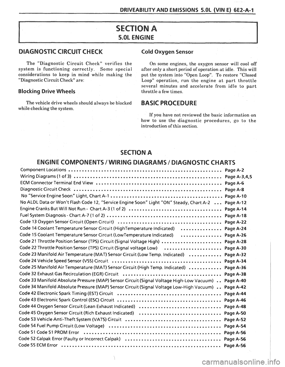
Component Locations ........................................................ Page A-2
Wiring Diagrams (1 of 3) ...................................................... Page A.3.4.5
ECM Connector Terminal End View .............................................. Page A-6
Diagnostic Circuit Check ...................................................... Page A-8
No "Service Engine Soon" Light. Chart A-1 ......................................... Page 14-10
No ALDL Data or Won't Flash Code 12. "Service Engine Soon" Light "ON" Steady. Chart A-2 ... Page A-I 2
Engine Cranks But Will Not Run . Chart A-3 (1 of 2) .................................. Page A-1 4
. Fuel System Diagnosis Chart A-7 (1 of 2) .......................................... Page A-1 8
Code 13 Oxygen Sensor Circuit (Open C~rcu~t) ...................................... Page A-22
Code 14 Coolant Temperature Sensor Circu~t (HighTemperature Indicated) ............... Page A-24
Code 15 Coolant Temperature Sensor Circu~t (LowTemperature Indicated) ............... Page A-26
Code 21 Throttle Position Sensor (TPS) Circu~t (S~gnal Voltage High) ...................... Page A-28
Code 22 Throttle Position Sensor (TPS) Circuit (Signal voltage Low) ..................... Page A-30
Code 23 Manifold Air Temperature (MAT) Sensor Circuit (Low Temp . Indicated) ............ Page A-32
Code 24 Vehicle Speed Sensor (VSS) Circuit ........................................ Page A-34
Code 25 Manifold Air Temperature (MAT) Sensor Circuit (High Temp . Indicated) ............ Page A-36
Code 32 Exhaust Gas Recirculation (EGR) Circuit .................................... Page A-38
Code 33 Manifold Absolute Pressure (MAP) Sensor Circuit (Signal Voltage High-Low Vacuum) . . Page A-40
Code 34 Manifold Absolute Pressure (MAP) Sensor Circuit (Signal Voltage Low-High Vacuum) . . Page A-42
Code 42 Electronic Spark Timing (EST) Circuit ...................................... Page A-44
Code 43 Electronic Spark Control (ESC) Circuit ...................................... Page A-46
Code 44 Oxygen Sensor Circuit (Lean Exhaust Indicated) .............................. Page A-48
Code 45 Oxygen Sensor Circuit (Rich Exhaust Indicated) .............................. Page A-50
Code 53 Vehicle Anti-Theft System (VATS) Circuit ................................... Page A-52
Code 54 Fuel Pump Circuit (Low Voltage) ......................................... Page A-54
Code 51 Code 51 PROM Error .................................................. Page A-56
Code 52 Calpak Error (Faulty or Incorrect Calpak) ................................... Page A-56
.......................................................... Code55ECMError PageA-56
Page 493 of 1825
6E2-A-2 5.OL (VIN E) DRIVEABILIW AND EMISSIONS
IFf SERIES VIN CODE: E
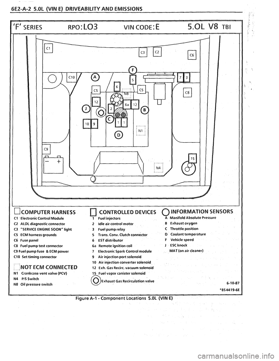
OCOMPUTER HARNESS
C1 Electronic Control Module
C2 ALDL diagnostic connector
C3 "SERVICE ENGINE SOON" light
C5 ECM harness grounds
C6 Fuse panel
C8 Fuel pump test connector
C9 Fuel pump fuse & ECM power
C10 Set timing connector
....,
: . ... 'NOT ECM CONNECTED
N1 Crankcase vent valve (PCV)
N4 PIS Switch
N8 Oil pressure switch
[7 CONTROLLED DEVICES 0 INFORMATION SENSORS
1 Fuel injectors A Manifold Absolute Pressure
2 Idle air control motor B Exhaust oxygen
3 Fuel pump relay
C Throttle position
5 Trans. Conv. Clutch connector
D Coolant temperature
6 EST distributor
F Vehicle speed
6a Remote ignition coil
J ESCknock
7 Electronic Spark Control module MAT (on air cleaner)
9 Air injection port solenoid
10 Air injection converter solenoid
12 Exh. Gas Recirc. vacuum solenoid
15 Fuel vapor canister solenoid
Exhaust Gas Recirculation valve
6-1
0-87
Figure A-I - Component Locations 5.OL (VIN E)
Page 513 of 1825
OXYGEN ( 0,) SENSOR GROUND
-
CODE 13
OXYGEN SENSOR CIRCUIT
(OPEN CIRCUIT)
5.OL (VIN E) ""FYERIES (TBI)
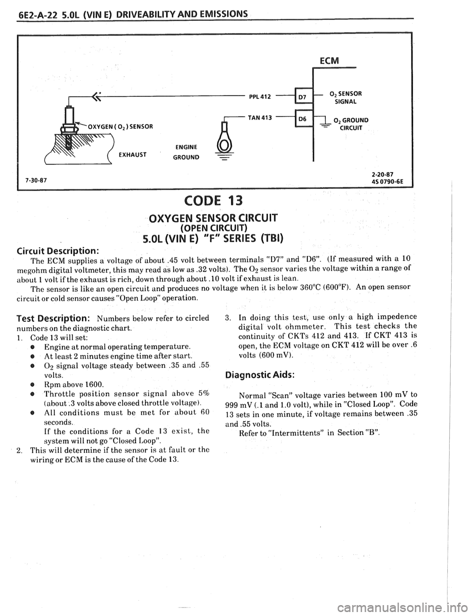
Circuit Description:
The ECM supplies a voltage of about .45 volt between terminals "D7" and "D6". (If measured with a 10
megohm digital voltmeter, this may read as low as .32 volts). The 02 sensor varies the voltage within a range of
about
1 volt if the exhaust is rich, down through about .10 volt if exhaust is lean.
The sensor is like an open circuit and produces no voltage when it is below 360°C (600°F). An open sensor
circuit or cold sensor causes "Open Loop" operation.
Test Description: Numbers below refer to circled 3. In doing this test, use only a high impedence
numbers on the diagnostic chart. digital
volt ohmmeter. This test
checks the
1. Code 13 will set: continuity of CKTs 412 and 413. If CKT 413 is
@ Engine at normal operating temperature. open,
the ECM voltage on CKT 412 will be over .6
@ At least 2 minutes engine time after start. volts (600 mV).
@ On signal
voltage steady between .35 and .55
volts. Diagnostic Aids:
@ Rpm above 1600.
@ Throttle position sensor signal above 5%
Normal "Scan" voltage varies between 100 mV to
(about .3 volts above closed throttle voltage). 999 mV (. 1 and 1.0 volt), while in "Closed Loop". Code @ must be met for about 13 sets in one minute, if voltage remains between .35
seconds. and .55 volts.
If the conditions for a Code
13 exist, the
Refer to "Intermittents" in Section "B". system will not go "Closed Loop".
2. This will determine if the sensor is at fault or the
wiring or ECM is the cause of the Code
13.
Page 515 of 1825
bE2-A-24 S.OL (VIN E) DRIVEABILITY AND EMlSSlONS
SENSOR GND
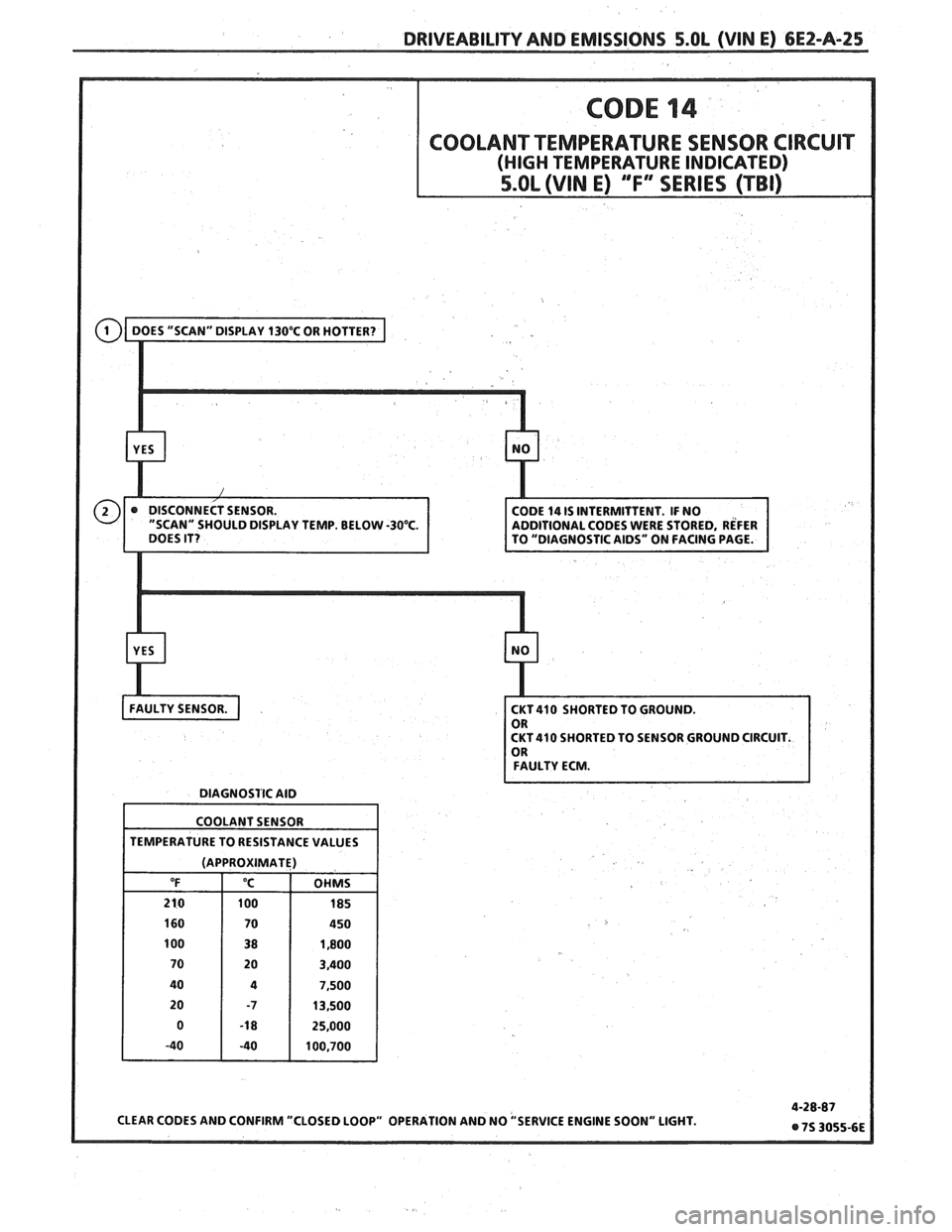
COD^ 14
COOLANT TEMPERATURE SENSOR CIRCUIT
(HIGH TEMPERATURE INDICATED)
5.OL (VIN E) "F"" SERIES (TBI)
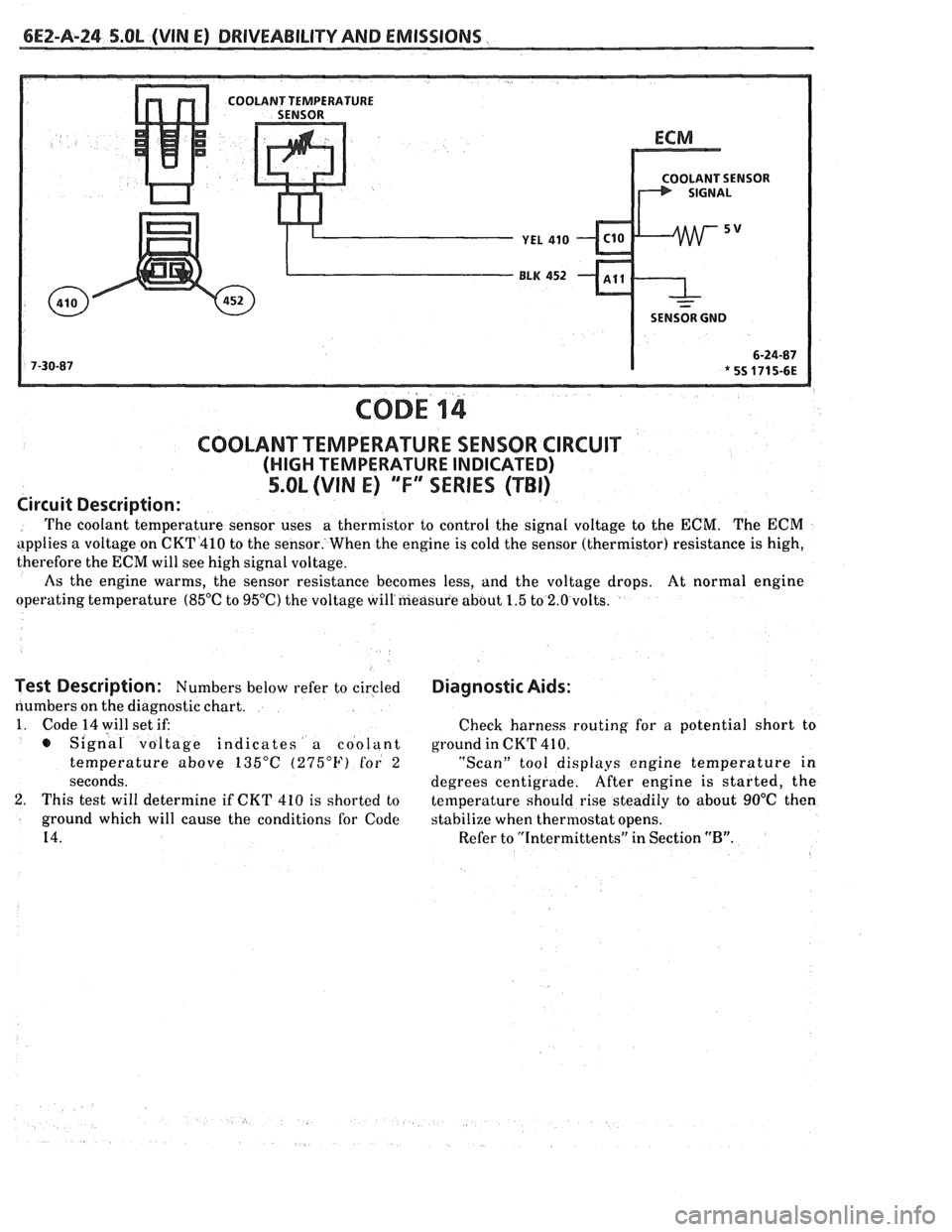
Circuit Description:
The coolant temperature sensor uses a
thermistor to control the signal voltage to the ECM. The ECM
applies a voltage on CKT4410 to the sensor. When the engine is cold the sensor (thermistor) resistance is high,
therefore the
ECM will see high signal voltage.
As the engine warms, the sensor resistance becomes less, and the voltage drops. At normal engine
operating temperature
(85°C to 95OC) the voltage will'measure about 1.5 to 2.0 volts.
Test Description: Numbers below refer to circled
numbers on the diagnostic chart.
1. Code 14 will set if:
s Signal voltage indicates a coolant
temperature above
135°C (275°F) for 2
seconds.
2. This test will determine if CKT 410 is shorted to
ground which will cause the conditions for Code
14.
Diagnostic Aids:
Check harness routing for a potential short to
ground in CKT
41 0.
"Scan" tool displays engine temperature in
degrees centigrade. After
engine is started, the
temperature should rise steadily to about
90°C then
stabilize when thermostat opens.
Refer to "Intermittents" in Section
"B".
Page 516 of 1825
DRIVEABILITY AND EMISSIONS 5.OL (VIN E) 6E2-A-25
LAY TEMP. BELOW -30°C.
CKT 410 SHORTED TO SENSOR GROUND CIRCUIT.
FAULTY ECM.
DIAGNOSTIC AID
COOLANT SENSOR
TEMPERATURE TO RESISTANCE VALUES
(APPROXIMATE)
Page 517 of 1825
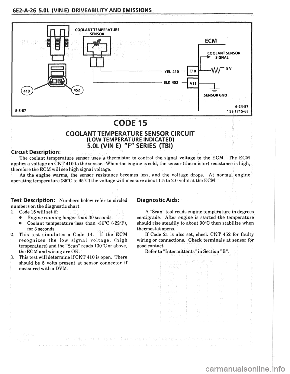
6EZ-A-26 5.8L (VIN E) DRIVEABILITY AND EMISSIONS
OLANT SENSOR
SENSOR GND
CODE 15
Test Description: Numbers below refer to circled
numbers on the diagnostic chart.
1. Code 15 will set if:
@ Engine running longer than 30 seconds.
@ Coolant temperature less than -30°C (-22"F),
for 3 seconds.
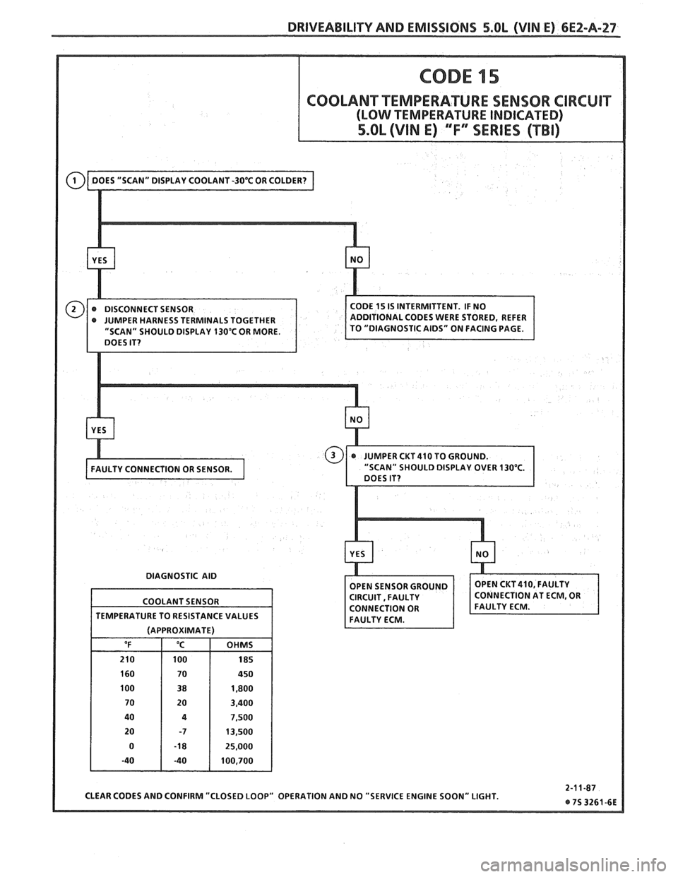
2. This test simulates a Code 14. If the ECM
recognizes the
low signal voltage, (high
temperature) and the "Scan" reads 130°C or above,
the ECM and wiring are OK.
3. This test will determine if CKT 410 is open. There
should be 5 volts present at sensor connector if
measured with a
DVM.
COOLANT TEMPERATURE SENSOR CIRCUIT
(LOMI TEMPERATURE INDICATED)
5.OL (VIM E) ""FYERIES (TBI)
Diagnostic Aids:
Circuit
Description:
The coolant temperature sensor uses a thermistor to control the signal voltage to the ECM. The ECM
applies a voltage on CKT 410 to the sensor. When the engine is cold, the sensor (thermistor) resistance is high,
therefore the ECM will see high signal voltage.
As the engine warms, the sensor resistance becomes less, and the voltage drops. At
normal engine
operating temperature (85°C to 95°C) the voltage will measure about 1.5 to 2.0 volts at the ECM.
A "Scan" tool reads engine temperature in degrees
centigrade. After engine is started the temperature
should rise steadily to about 90°C then stabilize when
thermostat opens.
If Code 21 is also set, check CKT 452 for faulty
wiring or connections. Check terminals at sensor for
good contact.
Refer to "Intermittents" in Section
"B".
~
Page 518 of 1825
DRIVEABILITY AND EMISSIONS S.OL (VIN E) 6E2-A-27
" SHOULD DISPLAY 130°C OR MORE.
DIAGNOSTIC AID
CLEAR CODES AND CONFIRM "CLOSED LOOP" OPERATION AND NO "SERVICE ENGINE SOON" LIGHT.
COOLANT
SENSOR
TEMPERATURE TO RESISTANCE VALUES
(APPROXIMATE)
"F "C OHMS
210 100 185
160 70 450
100 38 1,800
70 20 3,400
40
4 7,500
20 -7 13,500
0
-1 8 25,000
-40 -40 100,700
Page 519 of 1825
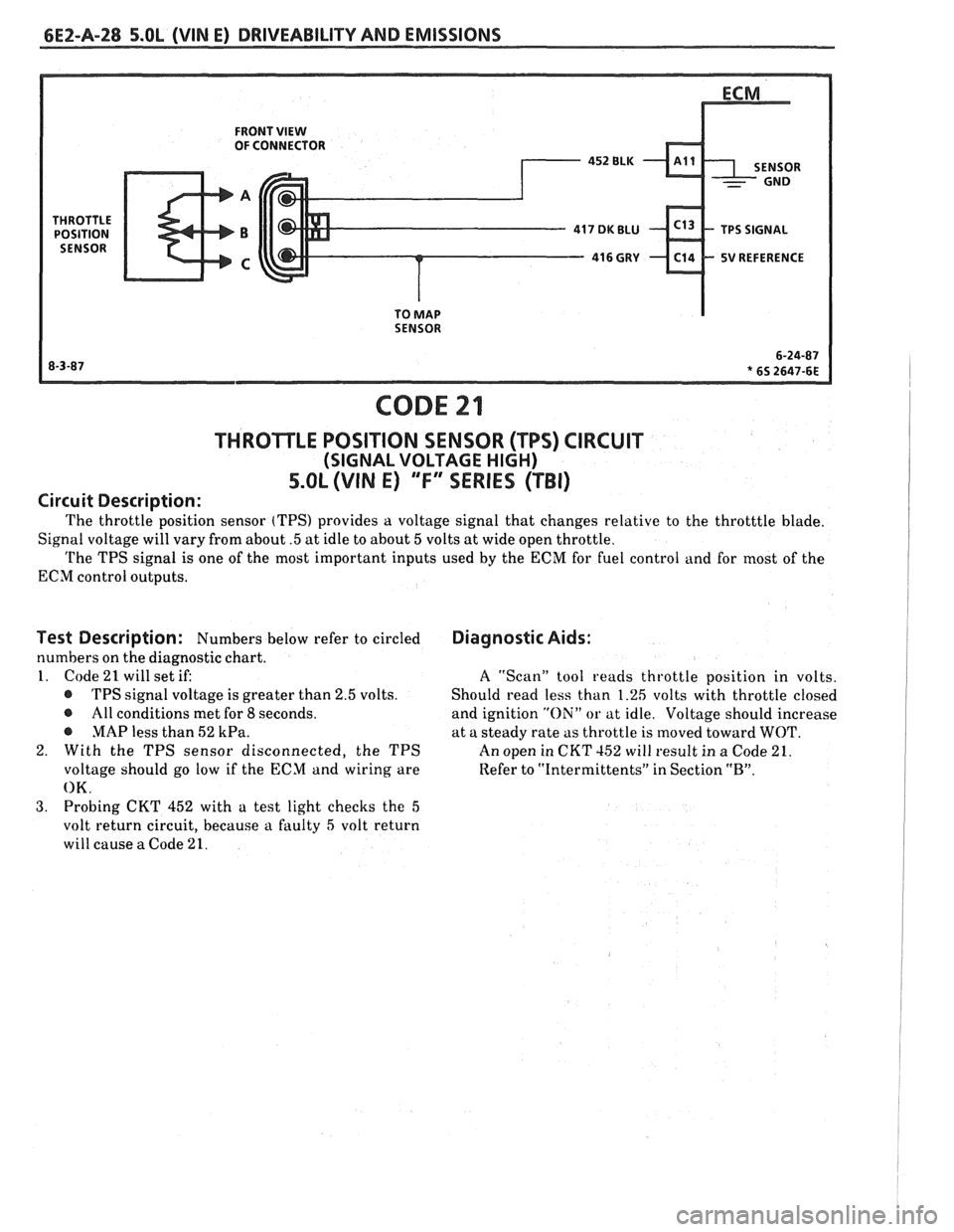
6EZ-A-28 5.OL (VIN E) DRIVEABILITY AND EMISSIONS
FRONT VIEW OF CONNECTOR
5V REFERENCE
TO
MAP SENSOR
CODE 21
THROTLE POSITION SENSOR (TPS) CIRCUIT
(SIGNAL VOLTAGE HIGH)
5.OL (VIN E) "F" "SERIES ("FBI)
Circuit Description:
The throttle position sensor (TPS) provides a voltage signal that changes relative to the throtttle blade.
Signal voltage will vary from about
.5 at idle to about 5 volts at wide open throttle.
The TPS signal is one of the most important inputs used by the ECM for fuel control and for most of the
ECM control outputs.
Test Description: Numbers below refer to circled
numbers on the diagnostic chart.
1. Code
21 will set if:
@ TPS signal voltage is greater than 2.5 volts.
@ All conditions met for 8 seconds.
@ MAP less than 52 kPa.
2. With the TPS sensor disconnected, the TPS
voltage should go low if the ECM and wiring are
OK.
3. Probing CKT 452 with a test light checks the 5
volt return circuit, because a faulty 5 volt return
will cause
a Code 21.
Diagnostic Aids:
A ''Scan" tool reads throttle position in volts.
Should read less than 1.26 volts with throttle closed
and ignition
"Oili" or at idle. Voltage should increase
at a steady rate as throttle is moved toward
WOT.
An open in CKT 152 will result in a Code 21.
Refer to
"Intermittents" in Section "B".