1988 PONTIAC FIERO sensor
[x] Cancel search: sensorPage 443 of 1825
![PONTIAC FIERO 1988 Service Repair Manual
6C-12 ENGINE FUEL
VIEW A
MAF SENSOR &
:~~~T
I3] DUCT
1 AIR CLEANER
1 ALIGN SLOT IN CLAMP WIRIB ON DUCT
LUBRICANT
(9985406)
1 THROTTLE BODY
Fig. 19 Air lnduction - LB9/L98
Fig. 20 Air PONTIAC FIERO 1988 Service Repair Manual
6C-12 ENGINE FUEL
VIEW A
MAF SENSOR &
:~~~T
I3] DUCT
1 AIR CLEANER
1 ALIGN SLOT IN CLAMP WIRIB ON DUCT
LUBRICANT
(9985406)
1 THROTTLE BODY
Fig. 19 Air lnduction - LB9/L98
Fig. 20 Air](/manual-img/50/57415/w960_57415-442.png)
6C-12 ENGINE FUEL
VIEW A
MAF SENSOR &
:~~~T
I3] DUCT
1 AIR CLEANER
1 ALIGN SLOT IN CLAMP WIRIB ON DUCT
LUBRICANT
(9985406)
1 THROTTLE BODY
Fig. 19 Air lnduction - LB9/L98
Fig. 20 Air Induction - LO3
Page 470 of 1825
IGNITION SYSTEM 6D4-1
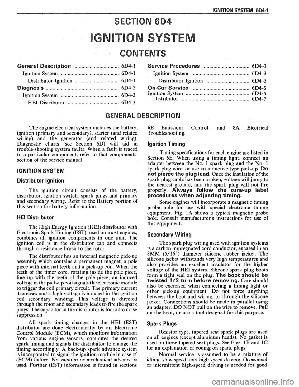
ON SYSTEM
CONTENTS
General Description ............................... 6D4-1 Service Procedures ............................. 6D4-3
Ignition System .......................................... 6D4-1
Ignition System .......................................... 6D4-3
Distributor Ignition ................................ 6D4-1
Distributor Ignition ................................ 6D4 -3
Diannosis .................................................... 6D4-3 On-Car Service ......................................... 6D4-5 -
Ignition System .......................................... (334-3 Ignition System ........................... .. .............. 6D4-5
Distributor ................................................. 6D4 -7 HE1 Distributor .................................... 6D4-3
GENERAL DESCRIPION
The engine electrical system includes the battery,
ignition (primary and secondary), starter (and related
wiring) and the generator (and related wiring).
Diagnostic charts (see Section 6D) will aid in
trouble-shooting system faults. When a fault is traced
to a particular component, refer to that components'
section of the service manual.
IGNITION SYSTEM
Distributor Ignition
The ignition circuit consists of the battery,
distributor, ignition switch, spark plugs and primary
and secondary wiring. Refer to the Battery portion of
this section for battery information.
PIE1 Distributor
The Nigh Energy Ignition (HEI) distributor with
Electronic Spark Timing (EST), used on most engines,
combines all ignition components in one unit. The
ignition coil is in the distributor cap and connects
through a resistance brush to the rotor.
The distributor has an internal magnetic pick-up
assembly which contains a permanent magnet, a pole
piece with internal teeth and a pick-up coil. When the
teeth of the timer core, rotating inside the pole piece,
line up with the teeth of the pole piece, an induced
voltage in the pick-up coil signals the electronic module
to trigger the coil primary circuit. The primary current
decreases and a high voltage is induced in the ignition
coil secondary winding. This voltage is directed
through the rotor and secondary leads to fire the spark
plugs. The capacitor in the distributor is for radio noise
suppression,
All spark timing changes in the
HE1 (EST)
distributor are done electronically by an Electronic
Control Module (ECM), which monitors information
from various engine sensors, computes the desired
spark timing and signals the distributor to change the
timing accordingly.
A back-up spark advance system
is incorporated to signal the ignition module in case of
(ECM) failure. No vacuum or mechanical advance is
used. Further (EST) information is found in sections 6E
Emissions Control, and
8A Electrical
Troubleshooting.
Ignition Timing
Timing specifications for each engine are listed in
Section
6E. When using a timing light, connect an
adapter between the No. 1 spark plug and the No. 1
spark plug wire, or use an inductive type pick-up.
Do
not pierce the plug lead.
Once the insulation of the
spark plug cable has been broken, voltage will jump to
the nearest ground, and the spark plug will not fire
properly.
Always follow the tune-up label
procedures when adjusting timing.
Some engines will incorporate a magnetic timing
probe hole for use with special electronic timing
equipment. Fig.
1A shows a typical magnetic probe
hole. Consult manufacturer's instructions for use of
this equipment.
Secondary Wiring
The spark plug wiring used with ignition systems
is a carbon impregnated cord conductor, encased in an
8MM (5/16") diameter silicone rubber jacket. The
silicone jacket withstands very high temperatures and
also provides an excellent insulator for the higher
voltage of the
HE1 system. Silicone spark plug boots
form a tight seal on the plug.
The boot should be
twisted 1/2 turn before removing. Care should
also be exercised when connecting a timing light or
other pick-up equipment. Do not force anything
between the boot and wiring, or through the silicone
jacket. Connections should be made in parallel using
an adapter. DO NOT pull on the wire to remove. Pull
on the boot, or use a tool designed for this purpose.
Spark Plugs
Resistor type, tapered seat spark plugs are used
on all engines (except aluminum heads). No gasket is
used on these tapered seat plugs. See Figs.
1B and 1C
for an explanation of coding on spark plugs.
Normal service is assumed to be a mixture of
idling, slow speed, and high speed driving. Occasional
or intermittent high-speed driving is needed for good
Page 480 of 1825
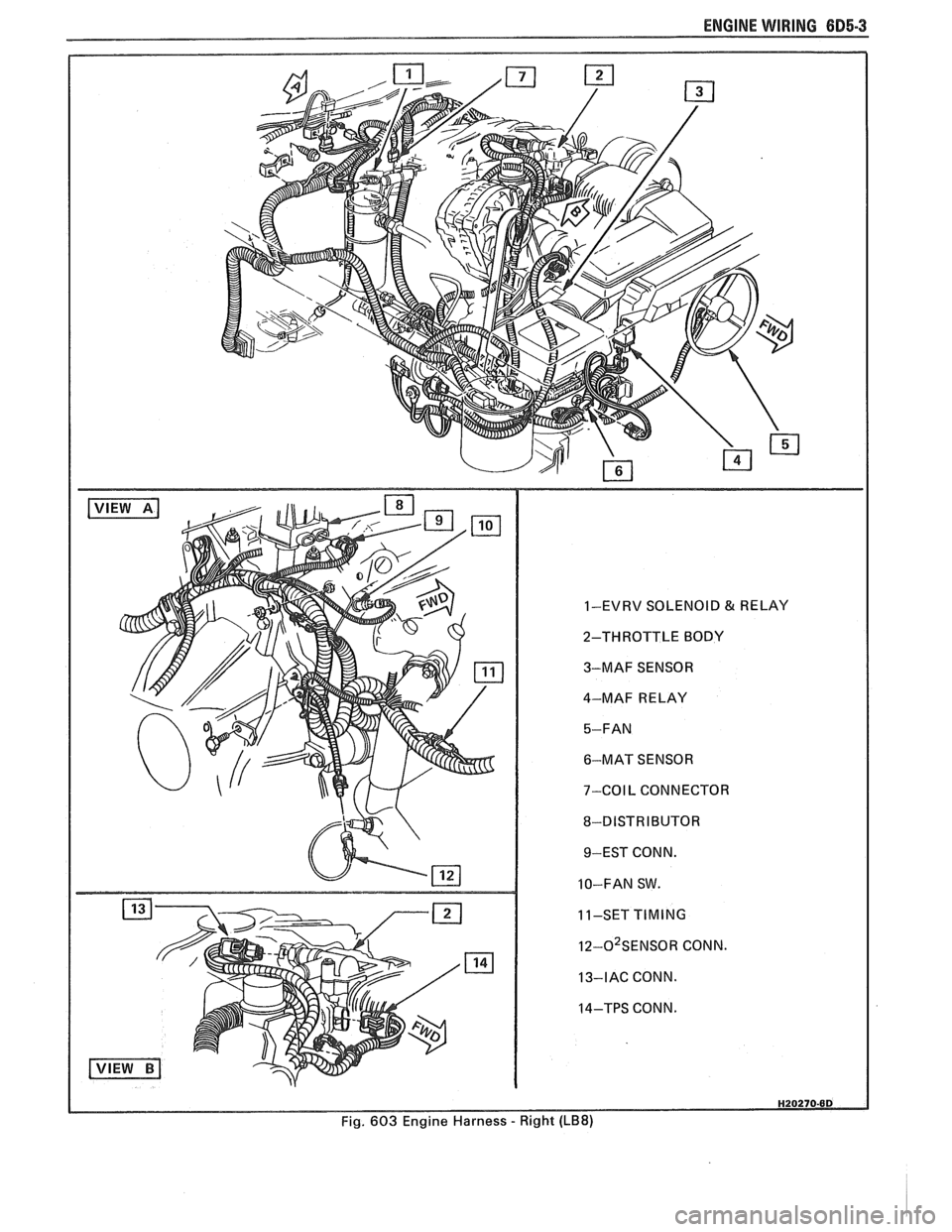
ENGINE WIRING 605.3
1-EVRV SOLENOID & RELAY
2-THROTTLE BODY
3-MAF SENSOR
4-MAF RELAY
6-MAT SENSOR
7-COIL CONNECTOR
8-DISTRIBUTOR 9-EST CONN.
10-FAN SW.
11-SET
TIMING
I~-O~SENSOR CONN.
13-IAC CONN.
14-TPS CONN.
Fig. 603 Engine Harness
- Right (LB8)
Page 486 of 1825
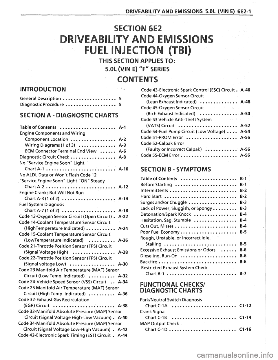
SECTION 6E2
TY AND EM
THIS SECTION APPLIES TO:
5.OL (VIN E) ""FYSERIES
CONTENTS
General Description .................... 5
Diagnostic Procedure ................... 5
SECTION A . DIAGNOSIIC CHARTS
Table of Contents ..................... A-1
Engine Components and Wiring
Component Location
................. A-2
Wiring Diagrams (1 of 3) .............. A-3
ECM Connector Terminal End View ...... A-6
Diagnostic Circuit Check ................. A-8
No "Service Eng~ne Soon" Light
Chart
A-1 .......................... A-10
No ALDL Data or Won't Flash Code 12
"Service Engine Soon" Light "ON" Steady
Chart A-2
.......................... A-1 2
Engine Cranks But Will Not Run
ChartA-3
(1 of 2) .................... A-14
Fuel System Diagnosis
ChartA-7(1 of 2) .................... A-18
Code 13-Oxygen Sensor Circuit (Open Circuit) . A-22
Code 14-Coolant Temperature Sensor Circuit
(HighTemperature Indicated) ........... A-24
Code 15-Coolant Temperature Sensor Circuit
(LowTemperature Indicated) .......... A-26
Code 21-Throttle Position Sensor (TPS) C~rcuit
(Signal Voltage High) ................ A-28
Code 22-Throttle Position Sensor (TPS) C~rcuit
(Signal voltage Low) ................. A-30
Code 23 Manifold Air Temperature (MAT) Sensor
. Circuit (Low Temp Indicated) .......... A-32
Code 43-Electronic Spark Control (ESC) Circuit . A46
Code 44-Oxygen Sensor Circu~t
(Lean Exhaust Indicated) .............. A-48
Code 45-Oxygen Sensor Circu~t
(Rich Exhaust Indicated) .............. A-50
Code 53 Vehicle Anti-Theft System
(VATS)
Circu~t ...................... A-52
Code 54-Fuel Pump Circuit (Low Voltage) .... A-54
Code 51 -PROM Error ................... A-56
Code 52-Calpak Error
(Faulty or Incorrect
Calpak) ............ A-56
Code 55-ECM Error ..................... A-56
SECTION B . SYMPTOMS
Table of Contents ..................... B-1
Before Starting ....................... B-1
Intermittents ......................... B-2
Hard Start ........................... 8-2
.................. Surges and/or Chuggle B-3
Lack of Power. Sluggish. or Spongy ......... 8-3
DetonationISpark Knock ................ 8-4
................ Hesitation. Sag. Stumble B-4
Cuts Out. Misses ....................... B-4
Poor Fuel Economy ..................... B-5
Rough. Unstable. or Incorrect Idle.
. Stalling ....................... ... B-5
Excessive Exhaust Emtss~ons or Odors ...... 8-6
Dieseling. Run-on ..................... 8-6
Backfire ............................. B-6
Restricted Exhaust System Check
Chart
B-1 .......................... 8-7
Code 24-Vehicle Speed Sensor (VSS) Circuit . . A-34
Code 25 Manifold Air Temperature (MAT) Sensor FUNCTIONAL CHECKS/
Circuit (High Temp . Indicated) .......... A-36 DIAGNOSqIC CHARTS
Code 32-Exhaust Gas Recirculat~on ParkINeutral Switch Diagnosis
........................ (EGR) Circuit ....................... A-38 Chart C- 1 A C1-12
Code 33-Manifold Absolute Pressure (MAP) Sensor Crank Signal
Circuit (Signal Voltage High-Low Vacuum)
. A-40 Chart C-1 B ........................ C1-14
Code %&Manifold Absolute Pressure (MAP) Sensor MAP
Output Check
......................... Circuit (Signal Voltage Low-High Vacuum) . A-42 ChartC-ID C1-16
Code 42-Electronic Spark Timing (EST) Circuit . A-44
Page 487 of 1825
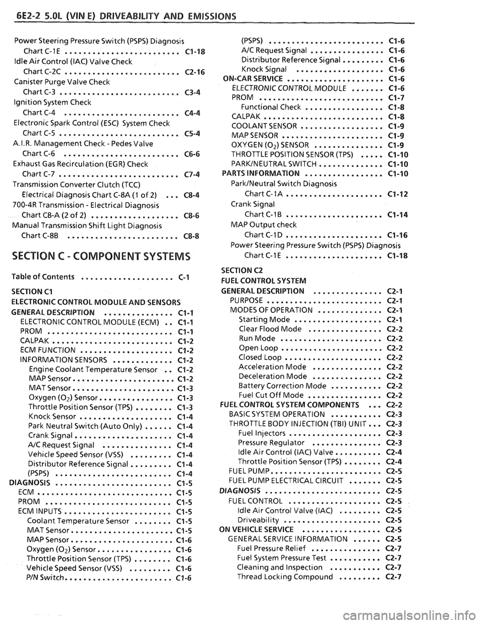
6E2-2 5.OL (VIN El DRlVEABlLlTV AND EMISSIONS
Power Steering Pressure Switch (PSPS) Diagnosis
Chart C-1
E ......................... C1-18
ldle Air Control (IAC) Valve Check
Chart C-2C
......................... C2-16
Canister Purge Valve Check
Chart C-3
.......................... C3-4
Ignition System Check
Chart C-4
......................... C4-4
Electronic Spark Control (ESC) System Check
Chart C-5
.......................... C5-4
A.I.R. Management Check . Pedes Valve
Chart C-6
......................... C6-6
Exhaust Gas Recirculation (EGR) Check
Chart C-7
.......................... C7-4
Transmission Converter Clutch (TCC)
Electrical Diagnosis Chart C-8A
(1 of 2) ... C8-4
700-4R Transmission . Electrical Diagnosis
Chart C8-A
(2 of 2) ................... C8-6
Manual Transmission Shift Light Diagnosis
Chart
C-8B ........................ C8-8
SECTION C . COMPONENT SYSTEMS
Table of Contents .................... C-1
SECTION
C1
ELECTRONIC CONTROL MODULE AND SENSORS
GENERAL DESCRIPTION
............... C1-1
ELECTRONIC CONTROL MODULE (ECM) . . C1-1
PROM ........................... C1-1
CALPAK .......................... C1-2
ECMFUNCTION .................... C1-2
INFORMATION SENSORS ............. C1-2
Engine Coolant Temperature Sensor . . C1-2
MAP Sensor ...................... C1-2
MAT Sensor ...................... C1-3
Oxygen (Oz) Sensor ................ C1-3
Throttle Position Sensor (TPS) ........ C1-3
Knock Sensor .................... C1-4
Park Neutral Switch (Auto Only) ...... C1-4
Crank Signal ..................... C1-4
A/C Request Signal ............... C1-4
Vehicle Speed Sensor (VSS) ......... C1-4
Distributor Reference Signal ......... C1-4
(PSPS) ......................... C1-4
DIAGNOSIS ......................... C1-5
ECM ............................. C1-5
PROM ........................... C1-5
ECMINPUTS ....................... C1-5
Coolant Temperature Sensor ........ C1-5
MAT Sensor ...................... C1-5
MAP Sensor ...................... C1-6
Oxygen (Oz) Sensor ................ C1-6
Throttle Position Sensor (TPS) ........ C1-6
Vehicle Speed Sensor (VSS) ......... C1-6
P/N Switch ....................... C1-6
(PSPS) ......................... C1-6
A/C Request Signal ................ C1-6
......... Distributor Reference Signal C1-6
Knock Signal ................... C1-6
..................... ON-CARSERVICE C1-6
....... ELECTRONIC CONTROL MODULE C1-6
........................... PROM C1-7
Functional Check ................. C1-8
.......................... CALPAK C1-8
.................. COOLANTSENSOR C1-9
MAPSENSOR e..................... C1-9
OXYGEN (02) SENSOR ............... C1-9
THROTTLE POSITION SENSOR (TPS) ..... C1-10
PARKINEUTRAL SWITCH .............. C1-10
PARTS INFORMATION ................. C1-10
ParklNeutral Switch Diagnosis
Chart
C-1A ..................... C1-12
Crank Signal
Chart
C-1B ..................... C1-14
MAP Output check
Chart C-1 D
..................... C1-16
Power Steering Pressure Switch (PSPS) Diagnosis
ChartC-lE ..................... C1-18
SECTION C2
FUEL CONTROL SYSTEM
GENERAL DESCRIPTION
............... C2-1
PURPOSE ...*..................... C2-1
MODES OF OPERATION .............. C2-1
Starting Mode ................... C2-1
Clear Flood Mode ................ C2-2
RunMode ...................... C2-2
Open Loop ...................... C2-2
Closed Loop ..................... C2-2
Acceleration Mode ............... C2-2
Deceleration Mode ............... C2-2
Battery Correction Mode ........... C2-2
Fuel Cut Off Mode ................ C2-2
... FUEL CONTROL SYSTEM COMPONENTS C2-2
BASIC SYSTEM OPERATION ........... C2-3
THROTTLE BODY INJECTION (TBI) UNIT ... C2-3
Fuel Injectors .................... C2-3
Pressure Regulator ............... C2-3
.......... Idle Air Control (IAC) Valve C2-4
........ Throttle Position Sensor (TPS) C2-4
FUELPUMP ........................ C2-5
....... FUEL PUMP ELECTRICAL CIRCUIT C2-5
DIAGNOSIS
......................... C2-5
FUEL CONTROL .................... C2-5
......... Idle Air Control Valve (IAC) C2-5
Dr~veability ..................... C2-5
ON VEHICLE SERVICE
................. C2-5
...... GENERALSERVICE INFORMATION C2-5
Fuel Pressure Relief ............... C2-7
........... Fuel System Pressure Test C2-7
Cleaning and lnspect~on ........... C2-7
......... Thread Lockrng Compound C2-7
Page 488 of 1825
DRIVEABILITY AND EMISSIONS 5.OL (VIN E) 6E2-3
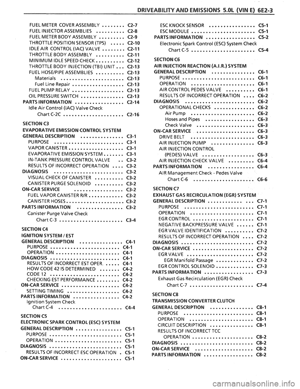
........ FUEL METER COVER ASSEMBLY C2-7
FUEL INJECTOR ASSEMBLIES .......... C2-8
FUEL METER BODY ASSEMBLY ......... C2-9
..... THROTTLE POSITION SENSOR (TPS) C2-10
IDLE AIR CONTROL (IAC) VALVE ........ 62-1 1
THROTTLE BODY ASSEMBLY
.......... C2-11
MINIMUM IDLE SPEED CHECK .......... C2-12
... THROTTLE BODY INJECTION (TBI) UNIT C2-13
FUEL
HOSEIPIPE ASSEMBLIES .......... C2-13
Materials ...................... C2-13
Fuel Line Repair .................. C2-13
FUEL PUMP RELAY .................. C2-13
............... OILPRESSURESWITCH C2-13
PARTS INFORMATION ................. C2-14
Idle Air Control (IAC) Valve Check
Chart C-2C
..................... C2-16
SECTION C3
EVAPORATIVE EMISSION CONTROL SYSTEM
GENERAL DESCRIPTION
............... C3-1
........................ PURPOSE C3-1
VAPOR CANISTER
................... C3-1
EVAPORATIVE EMISSION SYSTEM
....... C3-1
IN-TANK PRESSURE CONTROL VALVE
. . C3-2
.... RESULTS OF INCORRECT OPERATION C3-2
........................ DIAGNOSIS C3-2
VISUAL CHECK OF CANISTER
.......... C3-2
CANISTER PURGE SOLENOID
.......... C3-2
ON-CAR SERVICE ................. C3-2
FUEL VAPOR CANISTER
R/R ............ C3-2
CANISTER HOSES
.................... C3-2
PARTS INFORMATION ................ C3-2
Canister Purge Valve Check
Chart C-3
...................... C3-4
SECTION
C4
IGNITION SYSTEM I EST
GENERAL DESCRIPTION
............... C4-1
PURPOSE ........................ C4-1
OPERATION ...................... C4-1
.. DIAGNOSIS ................... ... C4-1
RESULTS OF INCORRECT EST OPER ...... C4-1
HOW CODE 42 IS DETERMINED ....... C4-2
CODE12 ........................ C4-2
CHECKING EST PERFORMANCE ........ C4-2
ON-CAR SERVICE .................... C4-2
SETTINGTIMING .................. C4-2
PARTS INFORMATION ................ C4-2
Ignition System Check
Chart C-4
................... .. . C4-4
SECTION C5
ELECTRONIC SPARK CONTROL (ESC) SYSTEM
GENERAL DESCRIPTION
................ C5-1
PURPOSE ..*...................... C5-1
OPERATION
....................... C5-1
DIAGNOSIS
......................... C5-1
RESULTS OF INCORRECT ESC OPERATION
. C5-1
ON-CAR SERVICE
..................... C5-1 ESC
KNOCK SENSOR
................ C5-1
ESCMODULE
...................... C5-1
PARTS INFORMATION ................. C5-2
Electronic Spark Control (ESC) System Check
Chart C-5
...................... C5-4
SECTION C6
AIR INJECTION REACTION (A.I.R.) SYSTEM
GENERAL DESCRIPTION
............... C6-1
PURPOSE
.*....................... C6-1
OPERATION
...................... C6-1
AIR CONTROL PEDES VALVE .......... C6-1
RESULTS OF INCORRECT OPERATION
.... C6-2
DIAGNOSIS
........................ C6-2
OPERATIONAL CHECKS
.....*........ C6-2
AirPump ...................... C6-2
Hoses and Pipes
................. C6-3
Check Valve
.................... C6-3
ON-CAR SERVICE
.................... C6-3
DRIVEBELT ...................... C6-3
AIR INJECTION PUMP
............... C6-3
AIR INJECTION CONTROL
(PEDES) VALVE
.................. C6-3
AIR INJECTION CHECK VALVE ......... C6-4
PARTS INFORMATION
................ C6-4
AIR Management Check
. Pedes Valve
Chart C-6
..................... C6-6
SECTION C7
EXHAUST GAS RECIRCULATION (EGR) SYSTEM
GENERAL DESCRIPTION
............... C7-1
PURPOSE
........................ C7-1
OPERATION
...................... C7-1
EGRCONTROL
..................... C7-1
NEGATIVE BACKPRESSURE VALVE
...... C7-1
EGR VALVE IDENTIFICATION
.......... C7-2
RESULTS OF INCORRECT OPERATION
.... C7-2
DIAGNOSIS
......................... C7-2
ON-CAR SERVICE
..................... C7-2
EGRVALVE
....................... C7-2
EGR Manifold Passage
............. C7-2
EGR CONTROL SOLENOID
............. C7-3
PARTS INFORMATION
................. C7-3
Exhaust Gas Recirculation (EGR) Check
Chart C-7
...................... C7-4
SECTION
C8
TRANSMISSION CONVERTER CLUTCH
GENERAL DESCRIPTION
............... C8-1
PURPOSE
........................ C8-1
OPERATION
...................... C8-1
CIRCUIT DESCRIPTION
............... C8-1
RESULTS OF INCORRECT TCC
OPERATION
..................... C8-2
DIAGNOSIS
......................... C8-2
ON-CAR SERVICE .................... C8-2
PARTS INFORMATION ................. C8-2
Page 489 of 1825
6E2-4 5.OL (VIN E) DRIVEABILITY AND EMISSIONS
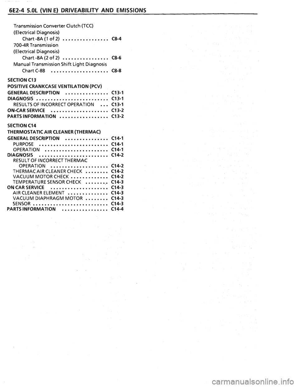
Transmission Converter Clutch (TCC)
(Electrical Diagnosis) Chart -8A
(1 of 2) ................ C8-4
700-4R Transmission
(Electrical Diagnosis) Chart -8A (2 of 2)
................ CS-6
Manual Transmission Shift Light Diagnosis
Chart C-8B
.................... CS-8
SECTION C13
POSITIVE CRANKCASE VENTILATION (PCV)
GENERAL DESCRIPTION
............... C13-1
DIAGNOSIS
......................... C13-1
RESULTS OF INCORRECT OPERATION ... C13-1
ON-CARSERVICE
.................... C13-2
PARTS INFORMATION
................. C13-2
SECTION C14
THERMOSTATIC AIR CLEANER (THERMAC)
GENERAL DESCRIPTION
............... 614-1
PURPOSE ........................ C14-1
OPERATION ...................... C14-1
DIAGNOSIS
........................ C14-2
RESULT OF INCORRECT THERMAC
OPERATION
.................... C14-2
THERMAC AIR CLEANER CHECK ........ C14-2
VACUUM MOTORCHECK ............. C14-2
TEMPERATURE SENSOR CHECK ......... C14-3
ON CAR SERVICE .................... C14-3
AIR CLEANER ELEMENT .............. C14-3
VACUUM DIAPHRAGM MOTOR ........ C14-3
SENSOR .......................... C14-3
PARTSINFORMATION ................ C14-4
Page 490 of 1825
DRIVEABILITY AND EMISSIONS 5.OL (VIN E) 6E2-5
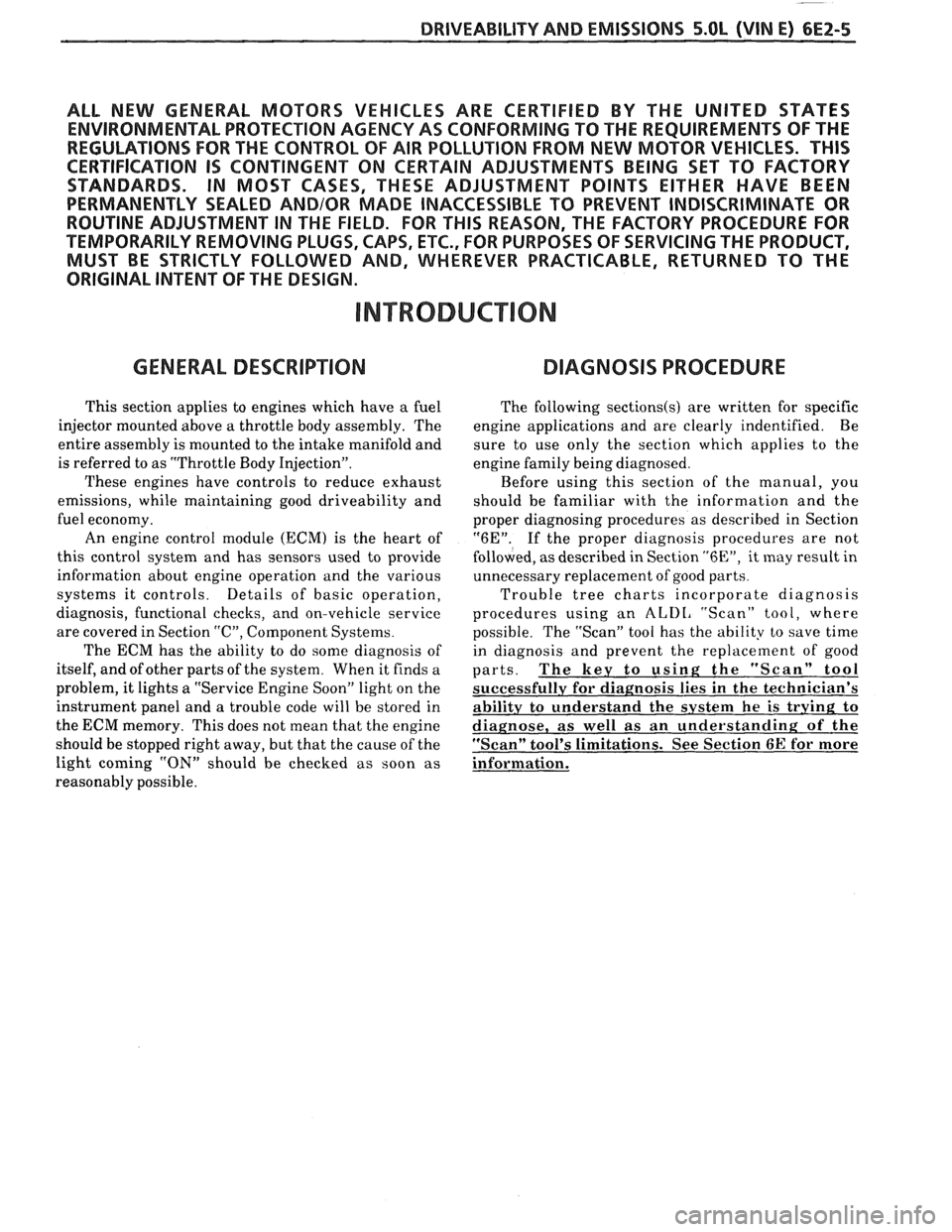
ALL NEW GENERAL MOTORS VEHICLES ARE CERTIFIED BY THE UNITED STATES
ENVIRONMENTAL PROTECTION AGENCY AS CONFORMING TO THE REQUIREMENTS OF THE
REGULATIONS FOR THE CONTROL OF AIR POLLUTION FROM NEW MOTOR VEHICLES.
THlS
CERTIFICATION IS CONTINGENT ON CERTAIN ADJUSTMENTS BEING SET TO FACTORY
STANDARDS. IN MOST CASES, THESE ADJUSTMENT POINTS EITHER HAVE BEEN
PERMANENTLY SEALED
AND/OR MADE INACCESSIBLE TO PREVENT INDISCRIMINATE OR
ROUTINE ADJUSTMENT IN THE FIELD. FOR
THlS REASON, THE FACTORY PROCEDURE FOR
TEMPORARILY REMOVING PLUGS, CAPS, ETC., FOR PURPOSES OF SERVICING THE PRODUCT,
MUST BE STRICTLY FOLLOWED AND, WHEREVER PRACTICABLE, RETURNED TO
THE
ORIGINAL INTENT OF THE DESIGN.
INTRODUCTION
GENERAL DESCRIPTION DIAGNOSIS PROCEDURE
This section applies to engines which have a fuel
injector mounted above a throttle body assembly. The
entire assembly is mounted to the intake manifold and
is referred to as "Throttle Body Injection".
These engines have controls to reduce exhaust
emissions, while maintaining good driveability and
fuel economy.
An engine control module
(ECM) is the heart of
this control system and has sensors used to provide
information about engine operation and the various
systems it controls. Details of basic operation,
diagnosis, functional checks, and on-vehicle service
are covered in Section
"C", Component Systems.
The
ECM has the ability to do some diagnosis of
itself, and of other parts of the system. When it finds a
problem,
it lights a "Service Engine Soon" light on the
instrument panel and a trouble code will be stored in
the ECM memory. This does not mean that the engine
should be stopped right away, but that the cause of the
light coming
"ON" should be checked as soon as
reasonably possible. The
following
sectionds) are written for specific
engine applications and are clearly indentified. Be
sure to use only the section which applies to the
engine family being diagnosed.
Before using this section of the manual, you
should be familiar with the information and the
proper diagnosing procedures as described in Section
"6E". If the proper diagnosis procedures are not
follo\l;red, as described in Section "6En, it may result in
unnecessary replacement of good parts.
Trouble tree charts incorporate diagnosis
procedures using an
ALDI, "Scan" tool, where
possible. The "Scan" tool has the ability to save time
in diagnosis and prevent the replacement of good
parts. The key to using; the "Scan" tool
successfully for diagnosis lies in the technician's
abilitv to understand the system
he is try in^ to
diagnose,
as well as an understanding of the
"Scan" tool's limitations. See Section
6E for more
information.