1988 PONTIAC FIERO fuel pump
[x] Cancel search: fuel pumpPage 434 of 1825
ENGINE FUEL 6C.3
a Fuel feed and return pipes are secured to the
underbody with clamps and screw assemblies.
The pipes should be inspected occasionally for
leaks, kinks or dents.
e Follow the same routing as the original pipe.
e Pipes must be properly secured to the frame to
prevent chafing. A minimum of 6 mm
(1/4")
clearance must be maintained around a pipe to
prevent contact and chafing.
MPFl Fuel Pipes
Due to the fact that fuel pipes are under high
pressure, these systems require special consideration for service.
Many feed and return pipes use screw couplings
with
"0" Rings. Any time these fittings are loosened
to service or replace components, ensure that:
a A backup wrench is used while loosening and
tightening the fitting.
e Check all "0" rings at fitting locations (if
applicable) for cuts or any damage and replace
any that appear worn or damaged.
e Use correct torque when tightening fittings.
If pipes are replaced always use original
equipment parts, or parts that meet GM
specifications.
Fuel and Vapor Hoses
NOTICE: Fuel and vapor hoses are specially
manufactured. If replacement becomes necessary,
it is important to use only replacement hoses
meeting GM Specification 6163-M. These hoses
are identified with the words "Fluoroelastomer"
on them. Hoses not so marked could cause early
failure, or fail to meet emission standards.
e Do not use rubber hose within 4" of any part of
the exhaust system, or within
10" of the catalytic
converter.
FUEL PUMP
The electric fuel pump is in the fuel tank. The
tank has an outlet for a vapor return system. Any vapor
which forms is returned to the fuel tank along with hot
fuel through a separate line. This greatly reduces any
possibility of vapor lock by keeping cool fuel from the
tank constantly circulating through the fuel pump.
FUEL PUMP RELAY
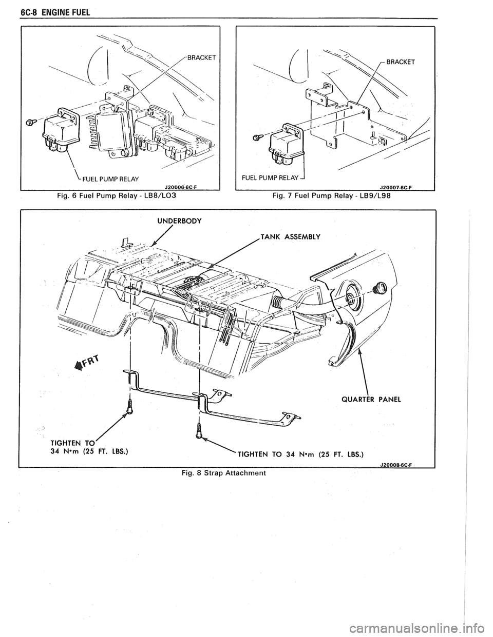
To control fuel pump operation, a fuel pump
relay is used.
When the ignition switch is turned to "RUN"
position, the fuel pump relay activates the electric fuel
pump for
1.5 to 2.0 seconds to prime the injector(s). If
the ECM does not receive reference pulses from the
distributor after this time, the ECM signals the relay
to turn off the fuel pump. The relay will once again
activate the fuel pump when the
ECM receives
distributor reference pulses.
Fuel Filter
CAUTION: To reduce the risk of fire
and personal injury, it is necessary
to
relieve the fuel system pressure
before servicing fuel system
components. (See Fuel System
Pressure Relief.)
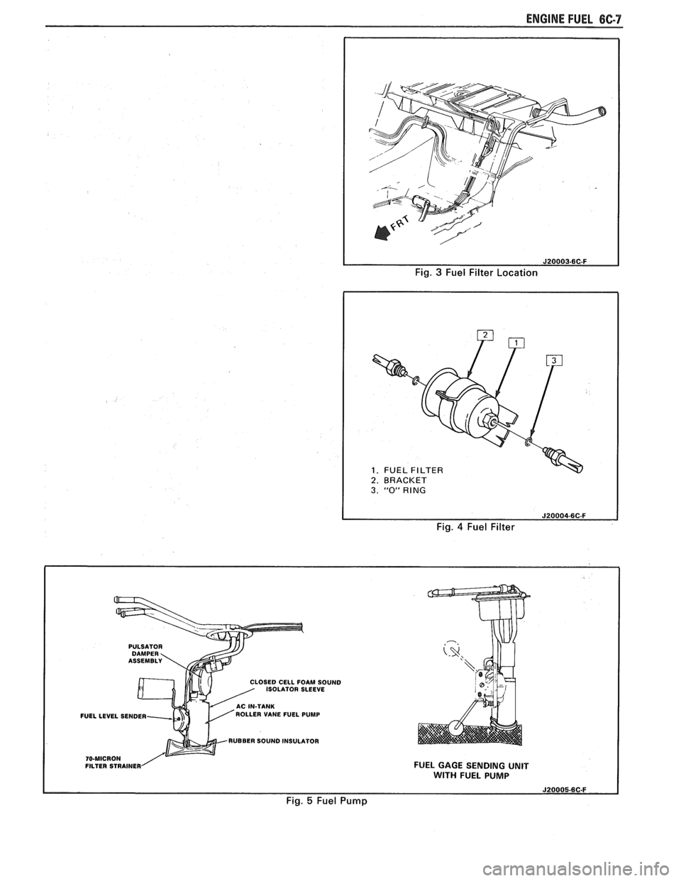
The inline filters can be found on the rear
crossmember of the vehicle. Always use a backup
wrench any time that the fuel filter is removed or
installed. Also make sure that a good
"0" Ring is used
at all screw couple locations. Torque on fittings is
30
N-m (22 lb. ft.).
FUEL TANK
The fuel tank is usually located under the rear of
the vehicle and a number of shapes and sizes are used
depending on the application.
The tank is held in place by two metal straps,
hinged (with a bolt through the hinge) and secured at
the opposite end with a nut and bolt assembly.
Anti-squeak pieces are used on top of the tank to
reduce rattles and other annoying noises.
The fuel tank, cap and lines should be inspected
for road damage, whch could cause leakage. Inspect
fuel cap for correct sealing and indications of physical
damage. Replace any damaged or malfunctioning
parts.
Before attempting service of any type on the fuel
tank, always
(1) remove negative battery cable from
battery, (2) place "no smoking" signs near work areas,
(3) be sure to have C02 fire extinguisher handy, (4)
wear safety glasses and
(5) siphon or pump fuel into an
explosion proof container.
Fuel Filler Gap
The fuel tank filler neck is equipped with a
screw-type cap. The threaded part of the cap requires
several turns counterclockwise to remove. The long
threaded area is designed to allow any remaining fuel
tank pressure to escape while the cap is being removed.
A built-in torque-limiting device prevents
overtightening. To install, turn the cap clockwise until
a clicking noise is heard. This signals that the correct
torque has been reached and the cap is fully seated.
N OTI G E: If a fuel filler cap requires replacement,
use only a cap with the same features. Failure to
use the correct cap can result in a serious
malfunction of the system.
Available on some models is an electric locking
fuel filler cap. Information on this option will be found
in Section
9E.
FUEL TANK FILLER NECK
To help prevent refueling with leaded gasoline,
the fuel filler neck on gasoline engine cars has a built-in
restrictor and deflector. The opening in the restrictor
will only admit the smaller unleaded gas nozzle spout,
which must be fully inserted to bypass the deflector.
Attempted refueling with a leaded gas nozzle or failure
Page 435 of 1825

6C-4 ENGINE FUEL
to fully insert the unleaded gas nozzle will result in
gasoline splashing back out of the filler neck.
Fuel Gage Sending Unit
The fuel gage sending unit is attached to the top
of the fuel tank. It is held in place with a cam lock ring
and a gasket is used between the tank and sending unit.
Sending units have three hoses attached. One line
is for the fuel feed. The second line is connected to the
vapor canister, to keep fuel vapor from getting into the
air (see Section 6E). The third line is used as a fuel
return line to the tank.
On some sending units a wire is attached to the
unit. On others the connectors attach directly to the
sender.
When a fuel gage sending unit is removed always
make sure to install the gasket and any power or
ground leads that were removed.
DIAGNOSIS
Fuel system diagnostic procedures are located in
Section(s) 6E1 thru 6E3.
SERVICE PROCEDURES
If the fuel system is suspected of delivering an
improper amount of fuel, it should be inspected and
tested in the vehicle, as follows:
1. Make certain that there is fuel in the tank.
2. With the engine running, inspect for leaks at all
fuel feed pipe and hose connections from
fuel
tank to injection pump. Tighten any loose
connections. Inspect all hoses for flattening or
kinks which would restrict the flow of fuel. Air
leaks or restrictions on suction side of fuel pump
will seriously affect pump output.
FUEL SYSTEM PRESSURE RELIEF
CAUTION: To reduce risk of fire and
personal injury, it is necessary to
relieve duel system pressure before
servicing fuel system components. To
do this:
Remove "fuel pump" fuse from fuse
block in passenger compartment.
e Crank engine - engine will start and run
until fuel supply remaining in fuel lines is
consumed. Engage starter for
3.0
seconds to assure relief of any remaining
pressure.
e With ignition "OFF", replace duel pump
fuse.
Unless this procedure
is followed before
servicing fuel lines
or connections, fuel
spray could occur.
When repair to the fuel system has been
completed, start engine and check all connections that
were loosened for possible leaks.
Refer to Section 6E for additional diagnosis of
engine fuel system.
Fuel Pump Flow Test
1. Test fuel
pump by connecting hose from EFI fuel
feed line to a suitable unbreakable container.
Apply battery voltage to the fuel pump test
terminal (terminal
"G" of ALCL).
2. Fuel pump should supply
1/2 pint or more in 15
seconds.
3. If flow is below minimum, check for fuel
restriction. If there is no restriction, check pump
pressure.
Fuel System Pressure Test
This test must be performed when diagnosing the
fuel system.
CAUTION: To reduce the risk of fire
and personal injury, it is necessary to
relieve fuel system pressure before
servicing fuel system components on
the
TBI system. To do this:
s Remove "Fuel Pump" fuse from fuse block in
passenger compartment.
e Crank engine. Engine will start and run until fuel
remaining in fuel lines is consumed. Crank the
starter for three seconds to assure that any
remaining pressure is relieved.
e With the ignition off, replace the "Fuel Pump"
fuse.
1. Obtain two
sections of
3/8" steel tubing. Each
should be about 254 mm (10 inches) long.
I
Double-flare one end of each section.
2. Install a flare nut on each section. Connect each i
of the above sections of tubing into the "flare nut 1
to flare nut adapters" that are included in J-29658 i
Gage Adapters.
3. Attach the
pipe and adapter assemblies to the
J-29658 gage.
4. Hoist the car.
5. Disconnect
front fuel feed hose from the fuel pipe
on the body.
1
6. Install a
254 mm (10 inch) length of 3/8" fuel
hose onto the fuel feed pipe on the body. Attach 1
I the other end of the hose onto one of the sections
of pipe mentioned in Step 1. Secure the hose
connections with clamps.
7. Attach the front fuel feed hose onto the other
i
section of tubing mentioned in Step 1. Secure the I
hose connection with a clamp. I
8. Start
the engine and check for leaks. I 9. Observe
the fuel pressure reading. It should be 62
to 90
kPa (9 to 13 psi). If not, refer to the I
appropriate Emissions Section.
10. Depressurize
the fuel system and remove the gage I
with adapters. Reconnect the fuel feed hose to the
pipe and torque the clamp to
1.7 N.m (1 5 lb. in.).
11. Lower
the car. Start the engine and check for fuel
leaks.
Fuel System Pressure Test- MPFl
Fuel system diagnosis is in Section 6E3, Chart
A-7.
Page 436 of 1825
ENGINE FUEL CC-5
FUEL TANK
Draining Fuel Tank
1. Disconnect the negative battery cable. Also have
a dry chemical (Class B) fire extinguisher near the
work area.
2. Use a hand operated pump device when possible
to drain as much fuel through the filler tube as
possible.
3. If
a hand operated pump device cannot be used
to complete the draining process, use a siphon at
the main (not return) fuel pipe at the fuel pump
or the fuel tank gage unit.
CAUTION: Never drain or store
gasoline in an open container due to
the possibility of fire or explosion.
4. Reinstall any removed hoses, lines and cap.
Removing Fuel Tank
1. Remove all fuel, see "Draining Fuel Tank".
2. Support
fuel tank and disconnect the two fuel
tank retaining straps.
3. Lower tank enough to disconnect sending unit
wire, hoses, and ground strap, if so equipped.
4. Remove tank from vehicle.
5. Remove sending unit.
Installing Fuel Tank
1. Reverse removal procedure.
2. Always replace "0" ring when tank unit has been
removed.
3. When reinstalling fuel tank, be sure to reinstall
anti-squeak pieces on top of the tank to reduce
rattles and other annoying noises.
4. Tighten fuel tank retaining strap bolts or screws.
Fuel System Cleaning
CAUTION: This procedure will NOT
remove all fuel vapor. Do not attempt
any repair
on tank or filler neck where
heat or flame is required, as an
explosion resulting in personal injury
could occur.
If trouble is due to contaminated fuel or foreign
material that is in the tank, it can usually be cleaned.
If tank is rusted internally, it should be replaced.
1. Disconnect negative battery cable.
2. Disconnect ignition engine harness connector.
Have dry chemical (Class B) fire extinguisher
near the work area.
3. Relieve fuel system pressure.
4. Drain fuel tank (see "Draining Fuel Tank").
5. Remove fuel tank (see "Fuel Tank Removal").
6. Remove external fuel filter and inspect for
contamination. If filter is plugged, replace.
7. Locate tank away from heat, flame, or other
source of ignition. Remove fuel gage sending unit
and fuel pump assembly, if so equipped, and
inspect condition of strainer. If strainer is
contaminated, a new strainer should be installed.
8. Complete draining of tank by rocking it and
allowing fuel to run out of fuel sending unit
opening.
9. Flush fuel tank with running hot water for at least
five minutes. Pour water out of fuel sending unit
opening. (Rock tank to be sure that removal of
water is complete.)
10. Disconnect fuel feed pipe and use air pressure to
clean fuel line. Apply air pressure in the opposite
direction fuel normally flows through the line. On
vehicles equipped with a fuel return line, clean
line in similar manner. Disconnect pipe at
throttle body unit and apply air pressure to clean
return line. Reconnect and torque all pipes to 30
N-m (22 1b. ft.).
11. Use low air pressure to clean pipes on fuel gage
sending unit.
112. Install new strainer on fuel gage sending unit, if
required. Install fuel gage sending unit and fuel
pump, with new gasket, into tank and install fuel
tank. Connect fuel gage wire harness to body
harness. Connect all fuel lines except feed line to
external fuel filter.
13. Disconnect fuel feed hose to chassis pipe at front.
Connect a hose to front end of chassis fuel feed
pipe and insert other end of hose into a one gallon
fuel can.
14. Connect battery cable.
15. Put six gallons of clean fuel into fuel tank and
apply 12 volts to Terminal
"G" of ALCL to
operate fuel pump. Pump two quarts of fuel into
fuel can. This will purge fuel pump.
16. Remove hose and connect fuel hose to chassis
pipe.
17. Check all connections
for leaks; tighten all hose
clamps.
Fuel Tank Purging Procedure
The following procedure is used prior to repairing
of fuel tank.
1. Remove fuel sending unit and fuel pump and
drain all remaining fuel from tank.
2. Visually inspect interior cavity of tank. If any fuel
is evident, drain again.
3. Move tank to flushing area (wash rack).
4. Fill tank completely with tap water, agitate
vigorously and drain.
5. Add gasoline emulsifying agent to the tank, refill
with water, agitate mixture for 10 minutes, and
drain tank completely.
For correct gasoline emulsifying agent-to-water
mixture, refer to the
manufacturer's
specifications. Use an available emulsifying
agent, such as "Product-Sol No.
913", or
equivalent.
6. When empty, refill the tank to overflowing with
water. Completely flush out remaining mixture
and empty tank.
7. If available, an explosion meter should be used Lo
check for negative reading.
8. Perform required service work.
Page 438 of 1825
ENGINE FUEL 6C-7
Fig. 3 Fuel Filter Location
1. FUEL 1 2. BRACKET I
I
3. "0" RING
Fig. 4 Fuel Filter
PULSATOR
LOSE0 CELL FOAM SOUND
ISOLATOR SLEEVE
FUELLEVEL SENDER ROLLER
VANE FUEL PUMP
RUBBER SOUND INSULATOR
FILTER STRAINER FUEL GAGE SENDING UNIT WITH FUEL PUMP
Fig. 5 Fuel Pump
Page 439 of 1825
6C-8 ENGINE FUEL
Fig. 6 Fuel Pump Relay - LB8/L03 Fig. 7 Fuel Pump Relay - LB9/L98
I UNDERBODY I
TANK ASSEMBLY
34
N*m (25 FT. LBS.)
TIGHTEN TO 34 N*m (25 FT. LBS.)
Fig. 8 Strap Attachment
Page 481 of 1825
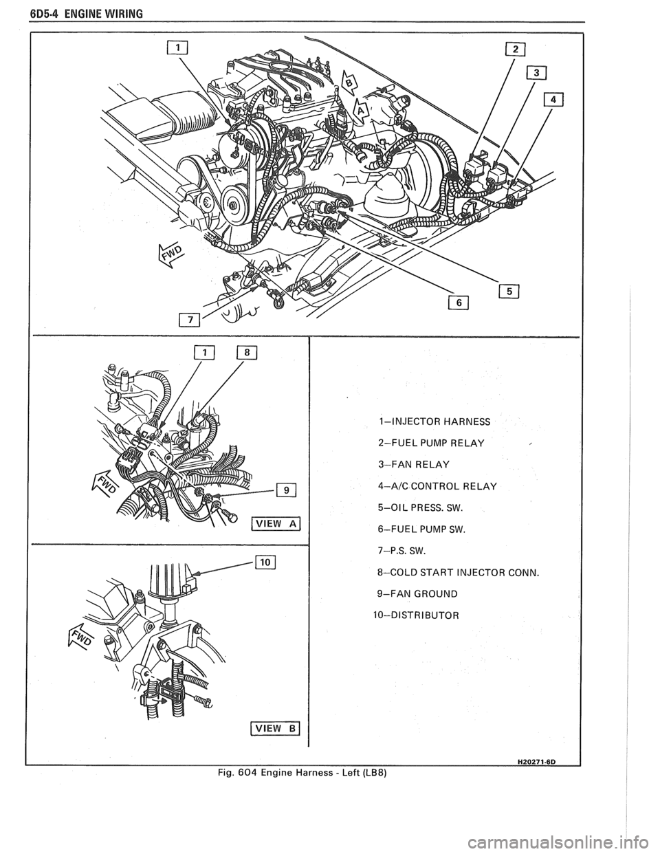
6D5-4 ENGINE WIRING
1-INJECTOR HARNESS
2-FUEL PUMP RELAY
3-FAN RELAY
4-AIC CONTROL RELAY
5-01 L PRESS. SW.
6-FUEL PUMP SW.
7-P.S. SW.
8-COLD START INJECTOR CONN.
9-FAN GROUND
Fig.
604 Engine Harness - Left (LB8)
Page 486 of 1825
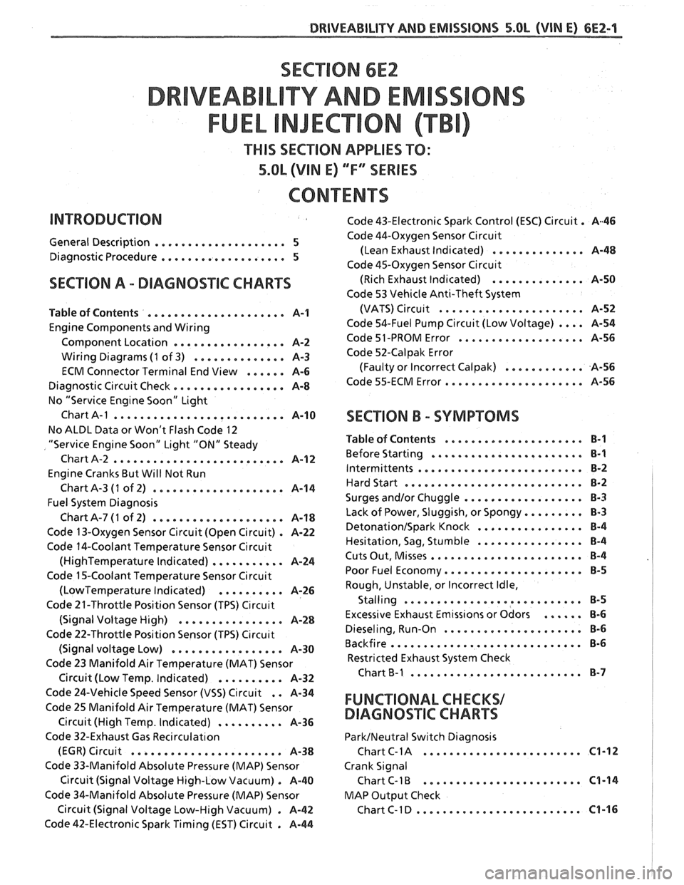
SECTION 6E2
TY AND EM
THIS SECTION APPLIES TO:
5.OL (VIN E) ""FYSERIES
CONTENTS
General Description .................... 5
Diagnostic Procedure ................... 5
SECTION A . DIAGNOSIIC CHARTS
Table of Contents ..................... A-1
Engine Components and Wiring
Component Location
................. A-2
Wiring Diagrams (1 of 3) .............. A-3
ECM Connector Terminal End View ...... A-6
Diagnostic Circuit Check ................. A-8
No "Service Eng~ne Soon" Light
Chart
A-1 .......................... A-10
No ALDL Data or Won't Flash Code 12
"Service Engine Soon" Light "ON" Steady
Chart A-2
.......................... A-1 2
Engine Cranks But Will Not Run
ChartA-3
(1 of 2) .................... A-14
Fuel System Diagnosis
ChartA-7(1 of 2) .................... A-18
Code 13-Oxygen Sensor Circuit (Open Circuit) . A-22
Code 14-Coolant Temperature Sensor Circuit
(HighTemperature Indicated) ........... A-24
Code 15-Coolant Temperature Sensor Circuit
(LowTemperature Indicated) .......... A-26
Code 21-Throttle Position Sensor (TPS) C~rcuit
(Signal Voltage High) ................ A-28
Code 22-Throttle Position Sensor (TPS) C~rcuit
(Signal voltage Low) ................. A-30
Code 23 Manifold Air Temperature (MAT) Sensor
. Circuit (Low Temp Indicated) .......... A-32
Code 43-Electronic Spark Control (ESC) Circuit . A46
Code 44-Oxygen Sensor Circu~t
(Lean Exhaust Indicated) .............. A-48
Code 45-Oxygen Sensor Circu~t
(Rich Exhaust Indicated) .............. A-50
Code 53 Vehicle Anti-Theft System
(VATS)
Circu~t ...................... A-52
Code 54-Fuel Pump Circuit (Low Voltage) .... A-54
Code 51 -PROM Error ................... A-56
Code 52-Calpak Error
(Faulty or Incorrect
Calpak) ............ A-56
Code 55-ECM Error ..................... A-56
SECTION B . SYMPTOMS
Table of Contents ..................... B-1
Before Starting ....................... B-1
Intermittents ......................... B-2
Hard Start ........................... 8-2
.................. Surges and/or Chuggle B-3
Lack of Power. Sluggish. or Spongy ......... 8-3
DetonationISpark Knock ................ 8-4
................ Hesitation. Sag. Stumble B-4
Cuts Out. Misses ....................... B-4
Poor Fuel Economy ..................... B-5
Rough. Unstable. or Incorrect Idle.
. Stalling ....................... ... B-5
Excessive Exhaust Emtss~ons or Odors ...... 8-6
Dieseling. Run-on ..................... 8-6
Backfire ............................. B-6
Restricted Exhaust System Check
Chart
B-1 .......................... 8-7
Code 24-Vehicle Speed Sensor (VSS) Circuit . . A-34
Code 25 Manifold Air Temperature (MAT) Sensor FUNCTIONAL CHECKS/
Circuit (High Temp . Indicated) .......... A-36 DIAGNOSqIC CHARTS
Code 32-Exhaust Gas Recirculat~on ParkINeutral Switch Diagnosis
........................ (EGR) Circuit ....................... A-38 Chart C- 1 A C1-12
Code 33-Manifold Absolute Pressure (MAP) Sensor Crank Signal
Circuit (Signal Voltage High-Low Vacuum)
. A-40 Chart C-1 B ........................ C1-14
Code %&Manifold Absolute Pressure (MAP) Sensor MAP
Output Check
......................... Circuit (Signal Voltage Low-High Vacuum) . A-42 ChartC-ID C1-16
Code 42-Electronic Spark Timing (EST) Circuit . A-44
Page 487 of 1825
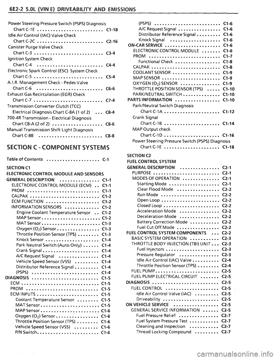
6E2-2 5.OL (VIN El DRlVEABlLlTV AND EMISSIONS
Power Steering Pressure Switch (PSPS) Diagnosis
Chart C-1
E ......................... C1-18
ldle Air Control (IAC) Valve Check
Chart C-2C
......................... C2-16
Canister Purge Valve Check
Chart C-3
.......................... C3-4
Ignition System Check
Chart C-4
......................... C4-4
Electronic Spark Control (ESC) System Check
Chart C-5
.......................... C5-4
A.I.R. Management Check . Pedes Valve
Chart C-6
......................... C6-6
Exhaust Gas Recirculation (EGR) Check
Chart C-7
.......................... C7-4
Transmission Converter Clutch (TCC)
Electrical Diagnosis Chart C-8A
(1 of 2) ... C8-4
700-4R Transmission . Electrical Diagnosis
Chart C8-A
(2 of 2) ................... C8-6
Manual Transmission Shift Light Diagnosis
Chart
C-8B ........................ C8-8
SECTION C . COMPONENT SYSTEMS
Table of Contents .................... C-1
SECTION
C1
ELECTRONIC CONTROL MODULE AND SENSORS
GENERAL DESCRIPTION
............... C1-1
ELECTRONIC CONTROL MODULE (ECM) . . C1-1
PROM ........................... C1-1
CALPAK .......................... C1-2
ECMFUNCTION .................... C1-2
INFORMATION SENSORS ............. C1-2
Engine Coolant Temperature Sensor . . C1-2
MAP Sensor ...................... C1-2
MAT Sensor ...................... C1-3
Oxygen (Oz) Sensor ................ C1-3
Throttle Position Sensor (TPS) ........ C1-3
Knock Sensor .................... C1-4
Park Neutral Switch (Auto Only) ...... C1-4
Crank Signal ..................... C1-4
A/C Request Signal ............... C1-4
Vehicle Speed Sensor (VSS) ......... C1-4
Distributor Reference Signal ......... C1-4
(PSPS) ......................... C1-4
DIAGNOSIS ......................... C1-5
ECM ............................. C1-5
PROM ........................... C1-5
ECMINPUTS ....................... C1-5
Coolant Temperature Sensor ........ C1-5
MAT Sensor ...................... C1-5
MAP Sensor ...................... C1-6
Oxygen (Oz) Sensor ................ C1-6
Throttle Position Sensor (TPS) ........ C1-6
Vehicle Speed Sensor (VSS) ......... C1-6
P/N Switch ....................... C1-6
(PSPS) ......................... C1-6
A/C Request Signal ................ C1-6
......... Distributor Reference Signal C1-6
Knock Signal ................... C1-6
..................... ON-CARSERVICE C1-6
....... ELECTRONIC CONTROL MODULE C1-6
........................... PROM C1-7
Functional Check ................. C1-8
.......................... CALPAK C1-8
.................. COOLANTSENSOR C1-9
MAPSENSOR e..................... C1-9
OXYGEN (02) SENSOR ............... C1-9
THROTTLE POSITION SENSOR (TPS) ..... C1-10
PARKINEUTRAL SWITCH .............. C1-10
PARTS INFORMATION ................. C1-10
ParklNeutral Switch Diagnosis
Chart
C-1A ..................... C1-12
Crank Signal
Chart
C-1B ..................... C1-14
MAP Output check
Chart C-1 D
..................... C1-16
Power Steering Pressure Switch (PSPS) Diagnosis
ChartC-lE ..................... C1-18
SECTION C2
FUEL CONTROL SYSTEM
GENERAL DESCRIPTION
............... C2-1
PURPOSE ...*..................... C2-1
MODES OF OPERATION .............. C2-1
Starting Mode ................... C2-1
Clear Flood Mode ................ C2-2
RunMode ...................... C2-2
Open Loop ...................... C2-2
Closed Loop ..................... C2-2
Acceleration Mode ............... C2-2
Deceleration Mode ............... C2-2
Battery Correction Mode ........... C2-2
Fuel Cut Off Mode ................ C2-2
... FUEL CONTROL SYSTEM COMPONENTS C2-2
BASIC SYSTEM OPERATION ........... C2-3
THROTTLE BODY INJECTION (TBI) UNIT ... C2-3
Fuel Injectors .................... C2-3
Pressure Regulator ............... C2-3
.......... Idle Air Control (IAC) Valve C2-4
........ Throttle Position Sensor (TPS) C2-4
FUELPUMP ........................ C2-5
....... FUEL PUMP ELECTRICAL CIRCUIT C2-5
DIAGNOSIS
......................... C2-5
FUEL CONTROL .................... C2-5
......... Idle Air Control Valve (IAC) C2-5
Dr~veability ..................... C2-5
ON VEHICLE SERVICE
................. C2-5
...... GENERALSERVICE INFORMATION C2-5
Fuel Pressure Relief ............... C2-7
........... Fuel System Pressure Test C2-7
Cleaning and lnspect~on ........... C2-7
......... Thread Lockrng Compound C2-7