1988 PONTIAC FIERO spark plugs
[x] Cancel search: spark plugsPage 381 of 1825
6A3-2 V-8 ENGINE
VALVE TRAIN
A very simple ball pivot-type train is used.
Motion is transmitted from the camshaft through the
hydraulic lifter and push rod to the rocker arm. The
rocker arm pivots on its ball and transmits the
camshaft motion to the valve. The rocker-arm ball is
retained by a nut.
HYDRAULIC VALVE LIFTERS
Hydraulic Valve Lifters are used to keep all parts
of the valve train in constant contact.
The hydraulic lifter assembly consists of: a roller,
the lifter body, which rides in the cylinder block boss,
a plunger, a push rod seat, a metering valve, a plunger
spring, a check ball and spring, a check ball retainer
and a push rod seat retainer.
When the lifter is riding on the low point of the
cam, the plunger spring keeps the plunger and push rod
seat in contact with the push rod.
When the lifter body begins to ride up the cam
lobe, the check ball cuts off the transfer of oil from the
reservoir below the plunger. The plunger and lifter
body then rise as a unit, pushing up the push rod and
opening the valve.
As the lifter body rides down the other side of the
cam, the plunger follows with it until the valve closes.
The lifter body continues to follow the cam to its low
point, but the plunger spring keeps the plunger in
contact with the push rod. The ball check valve will then
move off its seat and the lifter reservoir will
remain full.
INTAKE MANIFOLD
The intake manifold for those engines with
carburetors are made of cast iron or aluminum double
level design for efficient fuel distribution. An Exhaust
Gas Recirculation (EGR) port is also cast into the
manifold for the mixture of exhaust gases with the fuel
air mixture.
The intake manifold for those vehicles equipped
with
PFI is a cast aluminum unit. It centrally supports
a fuel rail with
8 fuel injectors.
EXHAUST MANIFOLDS
Two cast iron exhaust manifolds are used to
direct exhaust gases from the combustion chambers to
the exhaust system. The left hand side manifold
receives a heat shield that is used to route heated air
to the air cleaner. for better fuel vaporization during
warm-up.
COMBUSTION CHAMBERS
Combustion Chambers are cast to insure uniform
shape for all cylinders. Spark plugs are located between
the intake and exhaust valves. The contoured wedge
shape of the combustion chamber minimizes the
possibility of detonation, facilitates breathing and
provides swirling turbulence for smooth, complete
combustion.
ENGINE LUBRICATION
Full pressure lubrication through a full flow oil through drilled passages, to the camshaft and
filter, is furnished by a gear-type oil pump. The crankshaft to lubricate the bearings. The valve lifter oil
distributor, driven by a helical gear on the camshaft,
gallery feeds the valve lifters which, through hollow
drives the oil pump. The main oil gallery feeds oil,
push rods, feed the individually mounted rocker arms.
Page 401 of 1825
BA3-22 V-8 ENGINE
5. On the edge of gaging plastic envelope there is a
graduated scale which is correlated in
thousandths of an inch. Without removing the
gaging plastic, measure its compressed width (at
the widest point) with the graduations on the
gaging plastic envelope (fig. 6A3-40).
Normally main bearing journals wear evenly and
are not out-of-round. However, if a bearing is
being fitted to an out-of-round journal
(.00lU
max.), be sure to fit to the maximum diameter of
the journal: If the bearing is fitted to the
minimum diameter and the journal is
out-of-round
.001", interference between the
bearing and journal will result in rapid bearing
failure. If the flattened gaging plastic tapers
toward the middle or ends, there is a difference
in clearance indicating taper, low spot or other
irregularity of the bearing or journal. Be sure to
measure the journal with a micrometer if the
flattened gaging plastic indicates more than
.00lV
difference.
6. If the bearing clearance is within specifications,
the bearing insert is satisfactory. If the clearance'
is not within specifications, replace the insert.
Always replace both upper and lower inserts as
a unit.
If a new bearing cap is being installed and
clearance is less than
.00 1 ", inspect for burrs or
nicks; if none are found then install shims as
required.
I MEASURE END PLAY
Fig. 6A3-4 1 Measuring Crankshaft End Play - Typical
7. A standard, .001" or .002" undersize bearing may
produce the proper clearance. If not, it will be
necessary to regrind the crankshaft journal for
use with the next undersize bearing.
After selecting new bearing, recheck clearance.
8. Proceed to the next bearing. After all bearings
have been checked rotate the crankshaft to see
that there is no excessive drag.
When checking
&t 1 main bearing, loosen
accessory drive belts so as to prevent tapered
reading with plastic gage.
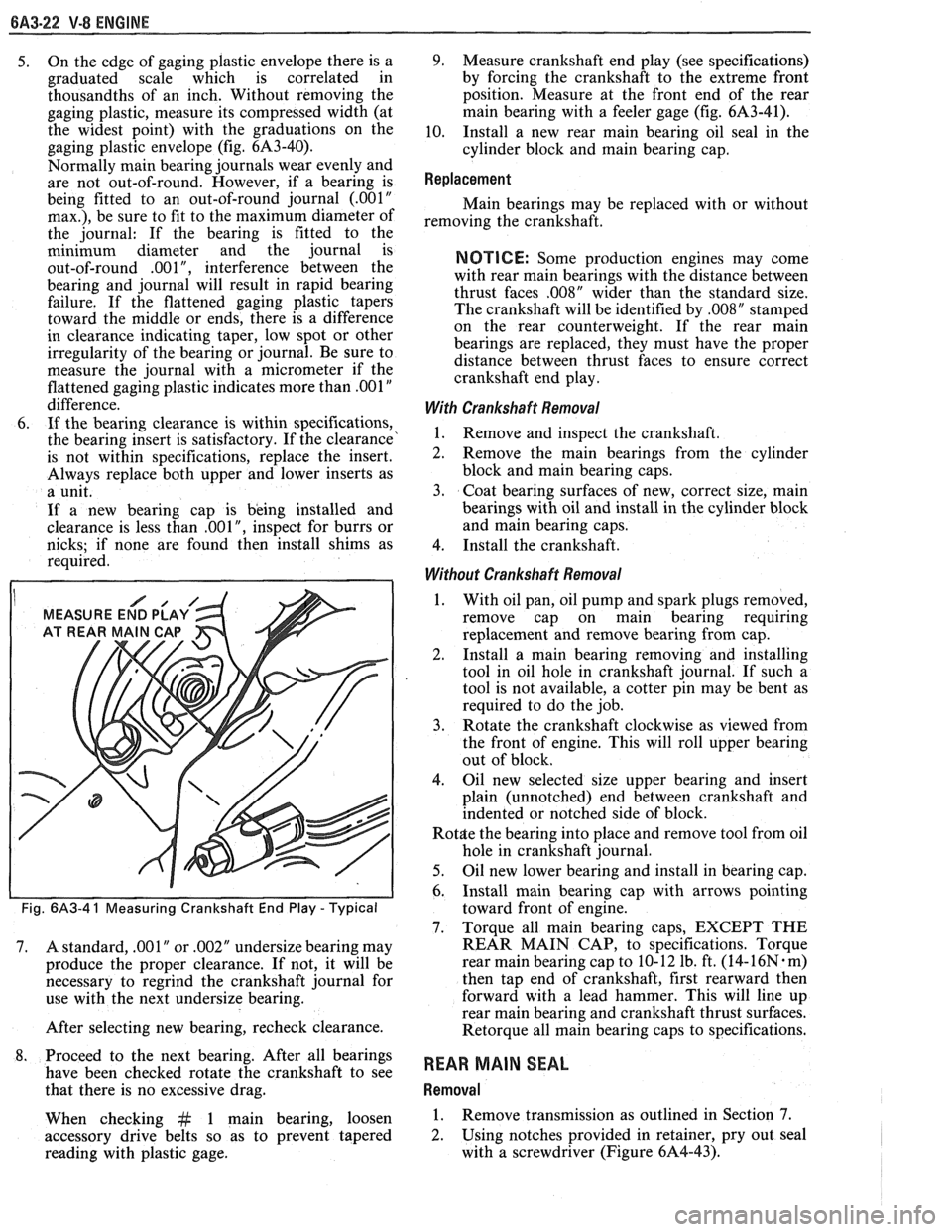
9. Measure crankshaft end play (see specifications)
by forcing the crankshaft to the extreme front
position. Measure at the front end of the rear
main bearing with a feeler gage (fig.
61\3-41),
10. Install a new rear main bearing oil seal in the
cylinder block and main bearing cap.
Replacement
Main bearings may be replaced with or without
removing the crankshaft.
NOTICE: Some production engines may come
with rear main bearings with the distance between
thrust faces
,008" wider than the standard size.
The crankshaft will be identified by
,008" stamped
on the rear counterweight. If the rear main
bearings are replaced, they must have the proper
distance between thrust faces to ensure correct
crankshaft end play.
With Crankshaft Removal
1. Remove and inspect the crankshaft.
2. Remove the main bearings from the cylinder
block and main bearing caps.
3. Coat bearing surfaces of new, correct size, main
bearings with oil and install in the cylinder block
and main bearing caps.
4. Install the crankshaft.
Without Crankshaft Removal
1. With oil pan, oil pump and spark plugs removed,
remove cap on main bearing requiring
replacement and remove bearing from cap.
2. Install a
main bearing removing and installing
tool in oil hole in crankshaft journal. If such a
tool is not available, a cotter pin may be bent as
required to do the job.
3. Rotate the crankshaft clockwise as viewed from
the front of engine. This will roll upper bearing
out of block.
4. Oil new selected size upper bearing and insert
plain (unnotched) end between crankshaft and
indented or notched side of block.
Rot$e the bearing into place and remove tool from oil
hole in crankshaft journal.
5. Oil new lower bearing and install in bearing cap.
6. Install main bearing cap with arrows pointing
toward front of engine.
7. Torque all main bearing caps, EXCEPT THE
REAR MAIN CAP, to specifications. Torque
rear main bearing cap to 10- 12 lb. ft. (14-
16N. m)
then tap end of crankshaft, first rearward then
forward with a lead hammer. This will line up
rear main bearing and crankshaft thrust surfaces.
Retorque all main bearing caps to specifications.
REAR MAIN SEAL
Removal
1. Remove transmission as outlined in Section 7.
2. Using notches provided
in retainer, pry out seal
with a screwdriver (Figure 6A4-43).
Page 407 of 1825
6A3-28 V-8 ENGINE
16. Install
radiator and fan shroud and reconnect
radiator and heater hoses.
17. Fill cooling system.
18. Fill
crankcase with oil. See owner's manual for
specifications.
19. Install air cleaner.
20. Install hood.
21. Connect battery cables.
NOTICE: To avoid possible arcing of battery,
connect positive battery cable first.
22. Start engine, check for leaks and check timing.
CRANKSHAFT
The crankshaft can be removed while the engine
is disassembled for overhaul, as previously outlined, or
without complete disassembly.
Removal
With the engine removed from the vehicle and the
transmission and/or clutch housing removed
from the engine, mount engine in stand and
clamp securely.
Remove the oil dip stick and oil dip stick tube, (if
applicable).
Remove the starting motor, clutch assembly (if
equipped) and flywheel.
Remove the spark plugs.
Remove crankshaft pulley and torsional damper.
Remove oil pan and oil pump.
Remove crankcase front cover, and if so
equipped, remove timing chain and camshaft
sprocket.
Check the connecting rod caps for cylinder
number identification. If necessary, mark them.
Remove the connecting rod caps and push the
pistons to top of bores.
Remove main bearing caps and lift crankshaft out
of cylinder block.
Remove rear main bearing oil seal and main
bearings from cylinder block and main bearing
caps.
Cleaning and Inspection
1. Wash crankshaft in solvent and dry with
compressed air.
2. Measure dimensions of main bearing journals and
crankpins with a micrometer for out-of-round,
taper or undersize. (See Specifications.) 3.
Check crankshaft for run-out by supporting at
the front and rear main bearings journals in
"V"
blocks and check at the front and rear
intermediate journals with a dial indicator. (See
Specifications.)
4. Replace or recondition the crankshaft if out of
specifications.
SPROCKET OR GEAR REPLACEMENT
e Remove crankshaft sprocket using Tool
5-5825, install using Tool J-5590.
Installation
1.
Install rear main bearing oil seal in cylinder block
and rear main bearing cap grooves. Install with
lip of seal toward front of engine. Where seal has
two lips install lip with helix towards front of
engine.
2. Lubricate lips of seal with engine oil. Keep oil off
parting line surface.
3. Install main bearings in cylinder block and main
bearing caps then lubricate bearing surface with
engine oil.
4. Install crankshaft, being careful not to damage
bearing surfaces.
5. Recheck bearing clearances using plastigage.
6. Apply a thin coat of brush-on type oil sealing
compound to block mating surface and
corresponding surface of cap only. Do not allow
sealant on crankshaft or seal.
7. Install main bearing caps with arrows pointing
toward front of engine.
8. Torque all except rear main bearing cap bolts to
specifications. Torque rear main bearing cap bolts
to 10-12 lbs. ft. (14-16
N.m)then tap end of
crankshaft, first rearward then forward with a
lead hammer. This will line up rear main bearing
and crankshaft thrust surfaces.
Retorque all main
bearing cap bolts to specifications.
9. Measure crankshaft end play with a feeler gage.
Force crankshaft forward and measure clearance
between the front of the rear main bearing and the
crankshaft thrust surface.
10. Install flywheel and torque to specifications. A
wood block placed between the crankshaft and
cylinder block will prevent crankshaft from
rotating.
Align dowel hole in flywheel with dowel
hole in crankshaft. On vehicles equipped
with automatic transmissions, install
flywheel with the converter attaching pads
towards transmission.
GENERAL DATA
TYPE .................................................................................................................................. 90" V-8
DISPLACEMENT
............................................................................... 305 Cu. In., 350 Cu. In.
......................................................... LITER (VIN) ................................... ...... 5.0, (E), (F), 5.7 (8)
RPO ......................................................................................................................... L03, LB9, L98
BORE ........................................................................................................................ 3.736, 4.000
STROKE
........................... .. ....................................................................................... 3.480, 3.480
COMPRESSION RATIO
................................................................................... 931, 931, 9.5:1
FIRING ORDER .................................................................................................... 1-8-4-3-6-5-7-2
Page 432 of 1825
ENGINE FUEL BC-1
SECTION 6C
NE FUEL
CONTENTS
General Description ..................................... 6C-1 Fuel
Cap ........................................................... 6C-3
.................................................. ............................................. Alcohol-In-Fuel 6C- 1 Fuel Filter Neck 6C-3
................... ............ Fuel Metering .................................................. 6C-2 Fuel Gage Sending Unit .. 6C-4
....................... ............................... Throttle Body Injection (TBI) .... 6C-2 Diagnosis ,. 6C-4 ................... Service
Procedures ............................................. 6C-4
Port Fuel Injection ...................................... 6C-2
Pressure Relief ........................................... 6C-4
Fuel Feed and Return Pipe
............................... 6C-2
Flow Test .................................................... 6C-4
Fuel Pipes (MPFI)
.......................................... 6C-3
Pressure Test - TBI ................................... 6C-4
Fuel and Vapor Hoses
....................................... 6C-3
Pressure Test - MPFI .................................... 6C-4
Fuel Pump ........................................................ 6C-3 ...................................................... Fuel Pump Relay .............................................. 6C-3 Fuel Tank 6C-4
Fuel Filter
......................................................... 6C-3 Accelerator Controls ...................................... 6C-5
Fuel Tank
....................................................... 6C-3
All new General Motors vehicles are certified by
the United States Environmental Protection Agency as
conforming to the requirements of the regulations for
the control of air pollution from new motor vehicles.
This certification is contingent on certain adjustments
being set to factory standards. In most cases, these
adjustment points either have been permanently
sealed and/or made inaccessible to prevent
indiscriminate or routine adjustment in the field. For
this reason, the factory procedure for temporarily
removing plugs, caps, etc., for purposes of servicing the
product must be strictly followed and, wherever
practicable, returned to the original intent of the
design.
GENERAL DESCRIPTION
All gasoline engines are designed to use only
unleaded gasoline. Unleaded gasoline must be used for
proper emission control system operation. Its use will
also minimize spark plug fouling and extend engine oil
life. Using leaded gasoline can damage the emission
control system and could result in loss of emission
warranty coverage.
All cars are equipped with an Evaporative
Emission System. The purpose of the system is to
minimize the escape of fuel vapors to the atmosphere.
Information on this system will be found in Section
6E2, or 6E3.
When working on the fuel system, there are
several things to keep in mind.
@ Any time fuel system is being worked on,
disconnect the negative battery cable
except for those tests where battery
Adhere to all Notices and Cautions.
Always keep a dry chemical (Class B) fire
extinguisher near the work area.
-
Always use a backup wrench when loosening or
tightening a screw couple fitting.
The torque on a screw fitting is
30 N-m (22 lb.
ft.).
Pipe is used on all MPFI, TPI, SFI, and TBI
applications. Fittings require the use of an
"0"
Ring. Replace all pipe with the same type of pipe
and fittings that were removed.
All fuel pipes must meet GM Specification
124-M, or its equivalent.
All fuel hoses must meet GM Specification
6163-M, or its equivalent.
Do not replace fuel pipe with fuel hose.
voltage is required.
@ On MPFI, TPI, SF1 and TBI systems, always A1cohol-ln-Fuel
relieve the line pressure before servicing any fuel Certain driveability complaints such as
system components. hesitation, lack of power, stall, no start, etc., may be
@ Do not repair the fuel system until you have read caused
by an excessive amount of alcohol-in-fuel. The
the copy and checked the illustrations relating to complaints
may be due to fuel system corrosion and
that repair. subsequent
fuel filter plugging, deterioration of rubber
Page 470 of 1825
IGNITION SYSTEM 6D4-1
ON SYSTEM
CONTENTS
General Description ............................... 6D4-1 Service Procedures ............................. 6D4-3
Ignition System .......................................... 6D4-1
Ignition System .......................................... 6D4-3
Distributor Ignition ................................ 6D4-1
Distributor Ignition ................................ 6D4 -3
Diannosis .................................................... 6D4-3 On-Car Service ......................................... 6D4-5 -
Ignition System .......................................... (334-3 Ignition System ........................... .. .............. 6D4-5
Distributor ................................................. 6D4 -7 HE1 Distributor .................................... 6D4-3
GENERAL DESCRIPION
The engine electrical system includes the battery,
ignition (primary and secondary), starter (and related
wiring) and the generator (and related wiring).
Diagnostic charts (see Section 6D) will aid in
trouble-shooting system faults. When a fault is traced
to a particular component, refer to that components'
section of the service manual.
IGNITION SYSTEM
Distributor Ignition
The ignition circuit consists of the battery,
distributor, ignition switch, spark plugs and primary
and secondary wiring. Refer to the Battery portion of
this section for battery information.
PIE1 Distributor
The Nigh Energy Ignition (HEI) distributor with
Electronic Spark Timing (EST), used on most engines,
combines all ignition components in one unit. The
ignition coil is in the distributor cap and connects
through a resistance brush to the rotor.
The distributor has an internal magnetic pick-up
assembly which contains a permanent magnet, a pole
piece with internal teeth and a pick-up coil. When the
teeth of the timer core, rotating inside the pole piece,
line up with the teeth of the pole piece, an induced
voltage in the pick-up coil signals the electronic module
to trigger the coil primary circuit. The primary current
decreases and a high voltage is induced in the ignition
coil secondary winding. This voltage is directed
through the rotor and secondary leads to fire the spark
plugs. The capacitor in the distributor is for radio noise
suppression,
All spark timing changes in the
HE1 (EST)
distributor are done electronically by an Electronic
Control Module (ECM), which monitors information
from various engine sensors, computes the desired
spark timing and signals the distributor to change the
timing accordingly.
A back-up spark advance system
is incorporated to signal the ignition module in case of
(ECM) failure. No vacuum or mechanical advance is
used. Further (EST) information is found in sections 6E
Emissions Control, and
8A Electrical
Troubleshooting.
Ignition Timing
Timing specifications for each engine are listed in
Section
6E. When using a timing light, connect an
adapter between the No. 1 spark plug and the No. 1
spark plug wire, or use an inductive type pick-up.
Do
not pierce the plug lead.
Once the insulation of the
spark plug cable has been broken, voltage will jump to
the nearest ground, and the spark plug will not fire
properly.
Always follow the tune-up label
procedures when adjusting timing.
Some engines will incorporate a magnetic timing
probe hole for use with special electronic timing
equipment. Fig.
1A shows a typical magnetic probe
hole. Consult manufacturer's instructions for use of
this equipment.
Secondary Wiring
The spark plug wiring used with ignition systems
is a carbon impregnated cord conductor, encased in an
8MM (5/16") diameter silicone rubber jacket. The
silicone jacket withstands very high temperatures and
also provides an excellent insulator for the higher
voltage of the
HE1 system. Silicone spark plug boots
form a tight seal on the plug.
The boot should be
twisted 1/2 turn before removing. Care should
also be exercised when connecting a timing light or
other pick-up equipment. Do not force anything
between the boot and wiring, or through the silicone
jacket. Connections should be made in parallel using
an adapter. DO NOT pull on the wire to remove. Pull
on the boot, or use a tool designed for this purpose.
Spark Plugs
Resistor type, tapered seat spark plugs are used
on all engines (except aluminum heads). No gasket is
used on these tapered seat plugs. See Figs.
1B and 1C
for an explanation of coding on spark plugs.
Normal service is assumed to be a mixture of
idling, slow speed, and high speed driving. Occasional
or intermittent high-speed driving is needed for good
Page 471 of 1825
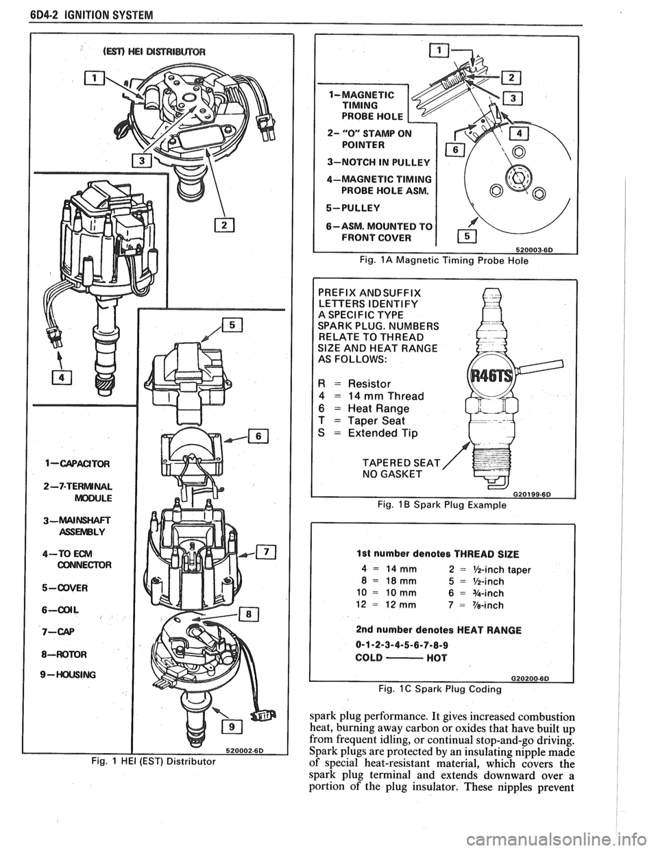
604-2 IGNITION SYSTEM
1-wACITm
2-7-TERNUNAL
ASSUVlBLY
4-TO Em
CONNECTOR
5-ODVER
8-WOMR
9- ING
Fig. 1 HE1 (EST) Distributor
2- "0" STAMP O
3-NOTCH IN PULLEY
4-MAGNETIC
TIMING
PROBE HOLE ASM.
5-PULLEY
6-ASM. MOUNTED TO
FRONT COVER
Fig. 1A Magnetic Timing Probe Hole
PREFIX ANDSUFFIX
LETTERS IDENTIFY
A SPECIFIC TYPE
SPARK PLUG. NUMBERS
RELATE TO THREAD
SlZE AND HEAT RANGE
AS FOLLOWS:
R = Resistor
4 = 14 mm Thread
6 = Heat Range
T
= Taper Seat
S
= Extended Tip
TAPERED SEAT NO GASKET
G20199-6D
Fig. 1 B Spark Plug Example
1st number denotes THREAD SlZE
4 = 14 mm 2 = %-inch taper
8 = 18mm 5 = %-inch
10 = 10 mm 6 = %-inch
12
= 12 mm 7 = Ve-inch
2nd number denotes HEAT RANGE
0-1-2-3-4-5-6-7-8-9
COLD
- HOT
Fig. 1 C Spark Plug Coding
spark plug performance. It gives increased combustion
heat, burning away carbon or oxides that have built up
from frequent idling, or continual stop-and-go driving.
Spark plugs are protected by an insulating nipple made
of special heat-resistant material, which covers the
spark plug terminal and extends downward over
a
portion of the plug insulator. These nipples prevent
Page 472 of 1825
IGNITION SYSTEM 6B4-3
flash-over, which causes engine misfiring. Do not
mistake corona discharge for flash-over, or a shorted
insulator. Corona is a steady blue light appearing
around the insulator, just above the shell crimp. It is
the visible evidence of a high-tension field and has no
effect on ignition performance. Usually it can be
detected only in darkness. This discharge may repel
dust particles, leaving a clear ring on the insulator just
above the shell. This ring is sometimes mistakenly
regarded as evidence that combustion gases have blown
out between shell and insulator.
lgnition Switch
The mechanical switch is located in the steering
column on the right hand side just below the steering
wheel. The electrical switching portion of the assembly
is separate from the key and lock cylinder. However,
both are synchronized and work in conjunction with
each other through the action of the actuator rod
assembly.
For a complete explanation of the key and lock
cylinder, and the actuator rod assembly, see
STEERING, Section
38. See Section 8 for electrical
switching.
DIAGNOSIS
IGNITION SYSTEM
Spark Plugs
Worn or dirty plugs may give satisfactory
operation at idling speed, but at higher RPM they
frequently fail. Faulty plugs are indicated in a number
of ways: poor fuel economy, power loss, loss of speed,
hard starting and generally poor engine performance.
Spark plugs may also fail due to carbon fouling,
excessive gap, or a broken insulator. Fouled plugs may
be indicated by black carbon
deposits. The black deposits are usually the result of
slow-speed driving and short runs, where sufficient
engine operating temperature is seldom reached. Worn
pistons, rings, faulty ignition, over-rich carburetion
and spark plugs which are too cold will also result in
carbon deposits.
Excessive gap wear, on plugs of low mileage,
usually indicates the engine is operating at high speeds,
or loads that are consistently greater than normal, or
that a plug which is too hot is being used. Electrode
wear may also be the result of plug overheating,
causcd
by combustion gases leaking past the threads due to
insufficient torquing of the spark plug. Excessively lean
carburetion will also result in accelerated electrode
wear.
Broken insulators are usually the result of
improper installation, or carelessness when regapping
the plug. Broken upper insulators usually result from
a poor fitting wrench, or an outside blow. The cracked
insulator may not show up right away, but will as soon
as oil or moisture penetrates the crack. The crack is
usually just below the crimped part of shell and may
not be visible.
Broken lower insulators usually result from
carelessness when regapping and generally are visible.
This type of break may result from the plug operating
too "hot", which may happen in periods of high-speed
operation or under heavy loads. When regapping a
spark plug, always make the gap adjustment by
bending the ground (side) electrode. Spark plugs with
broken insulators should always be replaced.
HE1 Distributor
See Unit Repair for distributor disassembly, test
and reassembly of individual distributor components,
when the distributor is removed from the vehicle. See
On-Car Service for distributor removal and installation
and for component removal with distributor in car. See
Section 6E for
HE1 and EST diagnosis.
SERVICE PROCEDURES
IGNITION SYSTEM
Distributor Ignition
NOTICE: This procedure is generally true for
most carlines. Where procedure is different, or
where additional information is required, see
"ON-CAR SERVICE" for specific
carline.
HE1 DISTRIBUTOR
Service Precautions
1. When making compression checks, disconnect
the ignition switch feed wire at the distributor.
When disconnecting this connector,
do not use
a screwdriver or tool to release the locking tab, as
it may break.
2. No periodic lubrication is required. Engine oil
lubricates the lower bushing and an oil-filled
reservoir provides lubrication for the upper
bushing. 3.
The tachometer (TACH) terminal is next to the
ignition switch (BAT) connector on the
distributor cap.
NOTICE: The tachometer terminal must
NEVER be allowed to touch ground, as damage
to the module and/or ignition coil can result.
Some tachometers currently in use may NOT be
compatible with the High Energy Ignition System.
Consult the manufacturer of the tachometer if
questions arise.
4. Dwell adjustment is controlled by the module,
and cannot be adjusted.
5. The material used to construct the spark plug
cables is very soft. This cable will withstand more
heat and carry a higher voltage, but scuffing and
cutting become easier. The spark plug cables
must be routed correctly to prevent
chafing or
cutting. See Spark Plug Section. When removing
Page 474 of 1825
IGNITION SYSTEM 6014.5
3. Rotor and cap. 4. Turn off the engine and remove the timing light.
Reconnect the number one spark plug wire, if
Set Ignition Timing removed.
Spark Plug Wires 1. Refer to the tune-up label located in the engine
compartment. Follow all instructions on the Use
care when removing spark plug wire boots
label. from
spark plugs. Twist the boot
1/2 turn before
removing and pull on the
boot only to remove the
With ignition off, connect the pick-up lead of
timing light to the number one spark plug. Use
a jumper lead between the wire and plug, or an
inductive type pick-up.
DO NOT pierce the wire,
or attempt to insert a wire between the boot and
the wire. Connect the timing light power leads
according to manufacturer's instructions.
Start the engine and aim the timing light at the
timing mark. The line on the balancer or pulley
will line up at the timing mark. If a change is
necessary, loosen the distributor hold-down
clamp bolt at the base of the distributor. While
observing the mark with the timing light, slighty
rotate the distributor until the line indicates the
correct timing. Tighten the hold-down bolt and
re-check the timing. wire.
When replacing plug wires, route the wires
correctly and through the proper retainers. Failure to
route the wires properly can lead to radio ignition noise
and crossfiring of the plugs, or shorting of the leads to
ground.
Special care should be exercised when reinstalling
spark plug boots, to assure that the metal terminal
within the boot is fully seated on the spark plug
terminal and that the boot has not moved on the wire.
If boot to wire movement has occurred, the boot will
give a false visual impression of being fully seated.
A
good check to assure that boots have been properly
assembled is to push sideways on the installed boots.
If they have been correctly installed, a stiff boot, with
only slight looseness, will be noted. If the terminal has
not been properly seated on the spark plug, only the
resistance of the rubber boot will be felt when pushing
sideways.
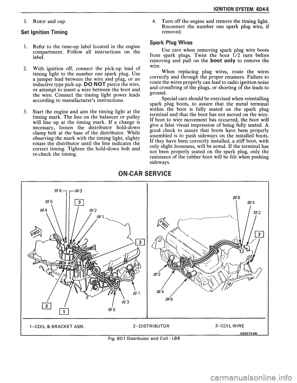
ON-CAR SERVICE
I I -COI L & BRACKET ASM. 2-DISTRIBUTOR 3-COIL WIRE I
Fig. 601 Distributor and Coil - LB8