1988 PONTIAC FIERO spare tire
[x] Cancel search: spare tirePage 234 of 1825
TIRES AND WHEELS 3E-3
METRIC WHEEL NUTS AND STUDS
Some models use metric wheel nuts and wheel
studs. The nut will have the word "metric" stamped on
its face and the stud will have the letter
"M" stamped
into the threaded end. The word "metric" is stamped
on its head.
The thread size of the metric wheel nuts and
wheel studs are
"MI2 x 1.5". These stand for:
M = Metric
12
= Diameter in millimeters
1.5
= Millimeters per thread
If a broken stud is found, see Section 3C (Front
Suspension) or Section 3D (Rear Suspension) for
replacement procedure.
INFLATION OF TIRES
The pressure recommended for any model is
carefully calculated to give a satisfactory ride,
handling, tread life and load carrying capacity.
Tire pressure, with tires cold, (after car has set for
three hours or more, or driven less than one mile)
should be checked monthly or before any extended trip
and set to the specifications on the tire placard located
on rear face of driver's door. Tire inflation pressure is
also given in Section OB.
Valve caps or extensions should be on the valves
to keep dust and water out.
1. For sustained driving at speeds up to 85
mph (140 km/h), in countries where such
speeds are allowed by law, your tires should be set
at the pressures recommended on your tire
placard.
Sustained driving at speeds
faster than
85 mph (140 km/h), where
permitted
by law, is not advised unless
your car has special high speed tires available
from many tire dealers.
2. Tire pressures may increase as much as 6 psi
when hot.
3. Higher
than recommended pressure can cause:
o Hard ride
o Tire bruising or carcass damage
Rapid tread wear at center of tire
4. Lower
than
recommended pressure can cause:
@ Tire squeal on turns
@ Hard steering
o Rapid and uneven wear on the edges of the
tread
Tire rim bruises and rupture
e Tire cord breakage
o High tire temperatures
o Reduced handling
High fuel consumption
5. Unequal pressure on same axle can cause:
Uneven braking
o Steering lead
o Reduced handling
e Swerve on acceleration
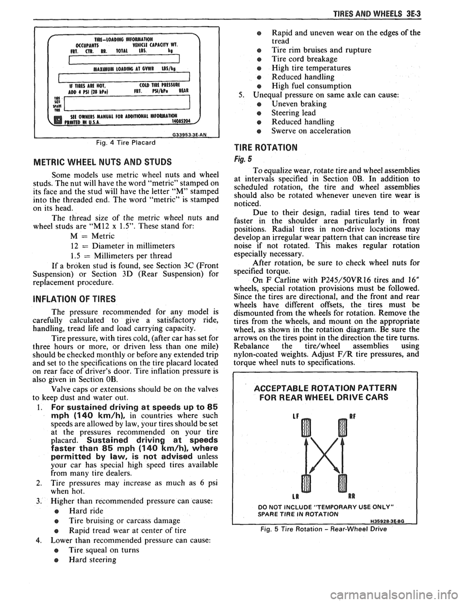
TlRE ROTATION
Fig. 5
To equalize wear, rotate tire and wheel assemblies
at intervals specified in Section OB. In addition to
scheduled rotation, the tire and wheel assemblies
should also be rotated whenever uneven tire wear is
noticed.
Due to their design, radial tires tend to wear
faster in the shoulder area particularly in front
positions. Radial
tires in non-drive
iocations may
develop an irregular wear pattern that can increase tire
noise if not rotated. This makes regular rotation
especially necessary.
After rotation, be sure to check wheel nuts for
specified torque.
On
F Carline with P245/50VR16 tires and 16"
wheels, special rotation provisions must be followed.
Since the tires are directional, and the front and rear
wheels have different offsets, the tires must be
dismounted from the wheels for rotation. Remove the
tires from the wheels, and mount on the appropriate
wheel, as shown in the rotation diagram. Be sure the
arrows on the tires point in the direction the tire turns.
Rebalance the
tire/wheel assemblies using
nylon-coated weights. Adjust
F/R tire pressures, and
torque wheel nuts to specifications.
ACCEPTABLE ROTATION PATTERN
FOR REAR WHEEL
DRIVE GARS
DO NOT INCLUDE "TEMPORARY USE ONLY" SPARE TlRE IN ROTATION
Fig. 5 Tire Rotation - Rear-Wheel Drive
Page 236 of 1825
TIRES AND WI4EELS 3E-5
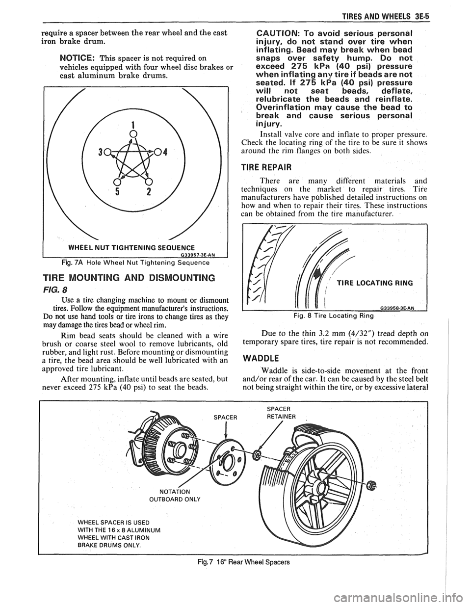
require a spacer between the rear wheel and the cast
iron brake drum.
NOTICE: This spacer is not required on
vehicles equipped with four wheel disc brakes or
cast aluminum brake drums.
Fig. 7A Hole Wheel Nut Tightening Sequence
TlRE MOUNTING AND DISMOUNTING
FIG. 8
Use a tire changing machine to mount or dismount
tires. Follow the equipment manufacturer's instructions.
Do not use hand tools or tire irons to change tires as they
may damage the tires bead or wheel rim.
Rim bead seats should be cleaned with a wire
brush or coarse steel wool to remove lubricants, old
rubber, and light rust. Before mounting or dismounting
a tire, the bead area should be well lubricated with an
approved tire lubricant.
After mounting, inflate until beads are seated, but
never exceed 275
kPa (40 psi) to seat the beads.
CAUTION: To avoid serious personal
injury, do not stand over tire when
inflating. Bead may break when bead
snaps over safety hump. Do not
exceed
275 kPa (40 psi) pressure
when inflating
any tire if beads are not
seated. If
275 kPa (40 psi) pressure
will not seat beads, deflate,
relubricate the beads and reinflate.
Overinflation may cause the bead to
break and cause serious personal
injury.
Install valve core and inflate to proper pressure.
Check the locating ring of the tire to be sure it shows
around the rim flanges on both sides.
TIRE REPAIR
There are many different materials and
techniques on the market to repair tires. Tire
manufacturers have published detailed instructions on
how and when to repair their tires. These instructions
can be obtained from the tire manufacturer.
TlRE LOCATING RING
naaaca a= AM
Fig. 8 Tire Locating Ring
Due to the thin 3.2 mm (4/32") tread depth on
temporary spare tires, tire repair is not recommended.
WADDLE
Waddle is side-to-side movement at the front
and/or rear of the car. It can be caused by the steel belt
not being straight within the tire, or by excessive lateral
WHEEL SPACER IS USED
WITH THE
16 x 8 ALUMINUM
WHEEL WITH CAST IRON
BRAKE DRUMS ONLY.
Fig, 7 16 Rear Wheel Spacers
Page 237 of 1825
3E-6 TIRES AND WHEELS
runout of the tire or wheel. Use a dial indicator on the
tire's sidewall and on the rim's flange to determine if
there is excessive lateral
runout.
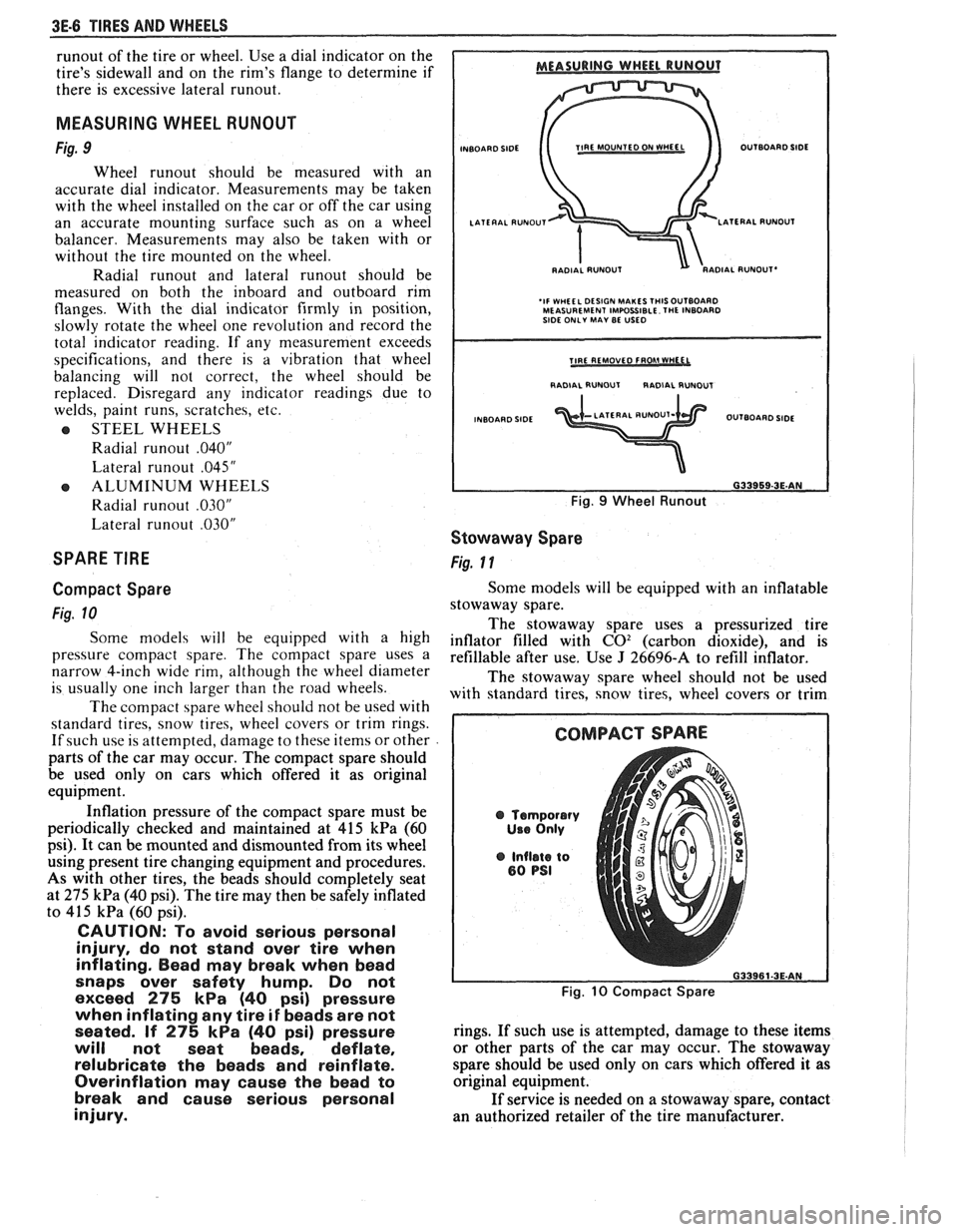
MEASURING WHEEL RUNOUT
Fig. 9
Wheel runout should be measured with an
accurate dial indicator. Measurements may be taken
with the wheel installed on the car or off the car using
an accurate mounting surface such as on a wheel
balancer. Measurements may also be taken with or
without the tire mounted on the wheel.
Radial
runout and lateral runout should be
measured on both the inboard and outboard rim
flanges. With the dial indicator firmly in position,
slowly rotate the wheel one revolution and record the
total indicator reading. If any measurement exceeds
specifications, and there is a vibration that wheel
balancing will not correct, the wheel should be
replaced. Disregard
any indicator readings due to
welds, paint runs, scratches, etc.
e STEEL WHEELS
Radial
runout .040"
Lateral runout .045"
e ALUMINUM WHEELS
Radial
runout .030"
Lateral runout .030"
SPARE TIRE
Compact Spare
Fig. 10
Some models will be equipped with a high
pressure compact spare. The compact spare uses a
narrow 4-inch wide rim, although the wheel diameter
is usually one inch larger than the road wheels.
The compact spare wheel should not be used with
standard tires, snow tires, wheel covers or trim rings.
If such use is attempted, damage to these items or other
parts of the car may occur. The compact spare should
be used only on cars which offered it as original
equipment.
Inflation pressure of the compact spare must be
periodically checked and maintained at
415 kPa (60
psi). It can be mounted and dismounted from its wheel
using present tire changing equipment and procedures.
As with other tires, the beads should completely seat
at
275 kPa (40 psi). The tire may then be safely inflated
to
415 kPa (60 psi).
CAUTION: To avoid serious personal
injury, do not stand over tire when
inflating. Bead may break when bead
snaps over safety hump. Do not
exceed
275 kPa (40 psi) pressure
when inflating any tire
if beads are not
seated. If
275 kPa (40 psi) pressure
will not seat beads, deflate,
relubricate the beads and reinflate.
Overinflation may cause the bead to
break and cause serious personal
injury.
INBOARD SIDE TIRE MOUNTED ON fVHEEL OUTBOARD SIDE
RADIAL
RUNOUT'
'IF WHEEL DESIGN MAKES THISOUTBOARD MEASUREMENT IMPOSSIBLE. THE INBOARD
SIDE ONLY MAY BE USED
I RADIAL RUNOUT RADIAL RUNDUT I
INBOARD SIDE OUTBOARD SIDE
Fig. 9 Wheel Runout
Stowaway Spare
Fig. 11
Some models will be equipped with an inflatable
stowaway spare.
The stowaway spare uses a pressurized tire
inflator filled with
C02 (carbon dioxide), and is
refillable after use. Use
J 26696-A to refill inflator.
The stowaway spare wheel should not be used
with standard tires, snow tires, wheel covers or trim
@ Temporary
Use Only
@ Inflate to 80 PSI
Fig. 10 Compact Spare
rings. If such use is attempted, damage to these items
or other parts of the car may occur. The stowaway
spare should be used only on cars which offered
it as
original equipment.
If service is needed on a stowaway spare, contact
an authorized retailer of the tire manufacturer.
Page 238 of 1825
TIRES AND WHEELS 3E-7
STMAWAY SPARE
TEMPORARY USE ONLV
Fig. 11 Stowaway Spare
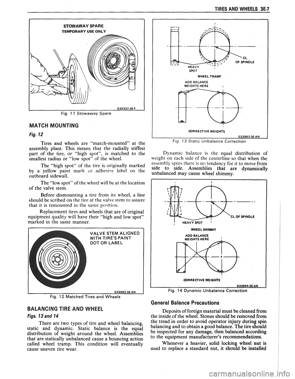
MATCH MOUNTING
Fig. 12
Tires and wheels are "match-mounted" at the
assembly plant. This means that the radially stiffest
part of the tire, or "high spot", is matched to the
smallest radius or "low spot" of the wheel.
The "high spot" of the tire is originally marked
by a yellow paint mark
or adhesive label on the
outboard sidewall.
The "low spot" of the wheel will be at the location
of the valve stem.
Before dismounting
a tire from its wheel, a line
should be scribed on the tire at the valve
stem to assure
that it is remounted
ill the same poqition.
Replacement tireq and wheels that are of original
equipment quality will have their "high and low spot"
marked in the same manner.
DOT OR LABEL
SPOT I WHEEL TRAMP I
ADD BALANCE WEIGHTS HERE I
I CORRECTIVE WEIGtiYS I
L G33963-3E.AN Fig 13 Stat~c Unbalance Correction
Dynam~c balance 1s the equal distribution of
weight on each side of the centerline so that when the
n\\embly spin there 14 no tendency for it to move from
side to side. Assemblies that are dynamically
unbalanced may cause wheel shimmy.
WHEEL SHlWWUV
ADDBALANCE , WEtGHTS HERE
Fig. 14 Dynamic Unbalance Correction
Fig.
12 Matched Tires and Wheels
General Balance Precautions
BALANCING TIRE AND WHEEL
Figs, 13 and 14
There are two types of tire and wheel balancing,
static and dynamic. Static balance is the equal
distribution of weight around the wheel. Assemblies
that are statically unbalanced cause a bouncing action
called wheel tramp. This condition will eventually
cause uneven tire wear. Deposits
of foreign material must be cleaned from
the inside of the wheel. Stones should be removed from
the tread in order to avoid operator injury during spin
balancing and to obtain a good balance. The tire should
be inspected for any damage, then balanced according
to the equipment manufacturer's recommendations.
Whenever a heavier, solid locking wheel nut is
used to replace a standard nut, it should
be installed
Page 417 of 1825
6B-8 ENGINE COOLING
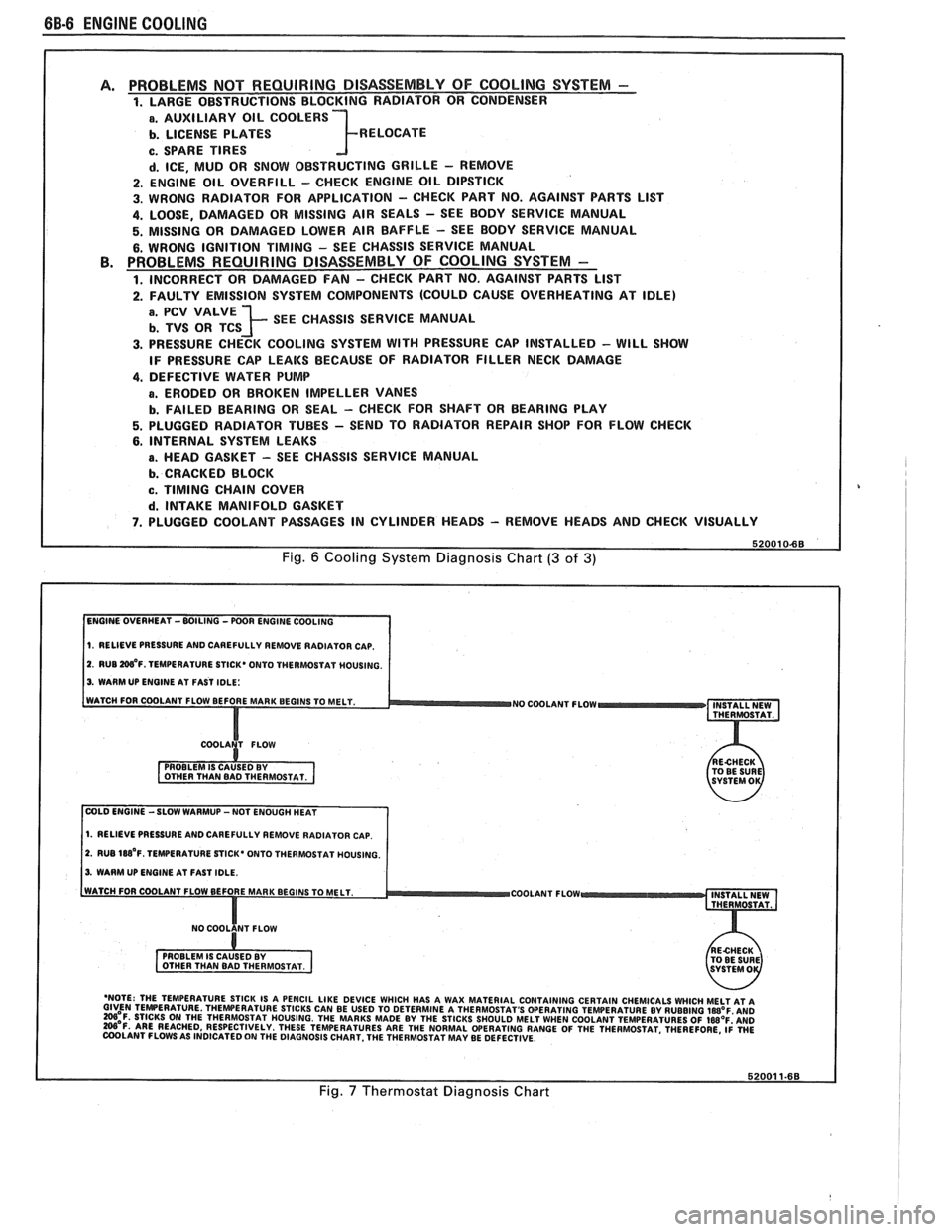
PROBLEMS NOT REQUIRING DISASSEMBLY OF COOLING SYSTEM - 1. LARGE OBSTRUCTIONS BLOCKING RADIATOR OR CONDENSER
a. AUXILIARY OIL COOLERS
b. LICENSE PLATES R ELOCATE
c. SPARE TIRES
d. ICE, MUD OR SNOW OBSTRUCTING GRILLE - REMOVE
2. ENGINE OIL OVERFILL - CHECK ENGINE OIL DIPSTICK
3. WRONG RADIATOR FOR
APPLICATION - CHECK PART NO. AGAINST PARTS LlST
4. LOOSE, DAMAGED OR MISSING AIR SEALS - SEE BODY SERVICE MANUAL
5. MISSING OR DAMAGED LOWER AIR BAFFLE - SEE BODY SERVICE MANUAL
6. WRONG IGNITION TIMING - SEE CHASSIS SERVICE MANUAL PROBLEMS REQUIRING DISASSEMBLY OF COOLING SYSTEM -
1. INCORRECT OR DAMAGED FAN - CHECK PART NO. AGAINST PARTS LlST
2. FAULTY EMISSION SYSTEM COMPONENTS (COULD CAUSE OVERHEATING AT IDLE)
; SEE CHASSIS SERVICE MANUAL
3. PRESSURE CHECK COOLING SYSTEM WITH PRESSURE CAP INSTALLED - WILL SHOW
IF PRESSURE CAP LEAKS BECAUSE OF RADIATOR FILLER NECK DAMAGE
4. DEFECTIVE WATER PUMP
a. ERODED OR BROKEN IMPELLER VANES
b. FAILED BEARING OR SEAL - CHECK FOR SHAFT OR BEARING PLAY
5. PLUGGED RADIATOR TUBES - SEND TO RADIATOR REPAIR SHOP FOR FLOW CHECK
6. INTERNAL SYSTEM LEAKS
B. HEAD GASKET - SEE CHASSIS SERVICE MANUAL
b. CRACKED BLOCK
c. TIMING CHAIN COVER
d. INTAKE MANIFOLD GASKET
7. PLUGGED COOLANT PASSAGES IN CYLINDER HEADS - REMOVE HEADS AND CHECK VISUALLY
Fig. 6 Cooling System Diagnosis Chart (3 of 3)
1. RELIEVE PRESSURE AND CAREFULLY REMOVE RADIATOR CAP.
2. RUB W'F. TEMPERATURE STICK* ONTO THERMOSTAT MOUSING.
3. WARM UP ENGINE AT FAST IDLE:
WATCH FOR COOLANT FLOW BEFORE MAR
NO COOLANT FLOW INSTALL NEW
THERMOSTAT.
COLD ENGINE -SLOW WARMUP -NOT ENOUGH HEAT
1. RELIEVE PRESSURE AND CAREFULLY REMOVE RADIATOR CAP.
2. RUB 188'~. TEMPERATURE STICK' ONTO THERMOSTAT HOUSING.
3. WARM UP ENGINE AT FAST IDLE.
COOLANT FLOW
- 'NOTE: THE TEMPERATURE STICK IS A PENCIL LIKE DEVICE WHICH HAS A WAX MATERIAL CONTAINING CERTAIN CHEMICALS WHICH MELT AT A GIVEN TEMPERATURE THEWERATURE STICKS CAN BE USED TO DETERMINE A THERMOSTAT'S OPERATING TEMPERATURE BY RUBBING laB°F AN0 =OF. STICKS ON THE THERMOSTAT HOUSING. THE MARKS MADE BY THE STICKS SHOULD MELT WHEN COOLANT TEMPERATURES OF IWOF'AND W'F. ARE REACHED, RESPECTIVELY. THESE TEMPERATURES ARE THE NORMAL WERATING RANGE OF THE THERMOSTAT. THEREFORE, ~i WE COOLANT FLOWS AS INDICATED ON THE DIAGNOSIS CHART. THE THERMOSTAT MAY BE DEFECTIVE.
Fig. 7 Thermostat Diagnosis Chart
Page 1684 of 1825
GENERAL INFORMAVlOM - F STYLE "1-3
Compartment lid hinges - part no. 1052196,
Lubriplate Auto Lube A; part no.
1052349,
Lubriplate Spray Lube A, part no. 8915,
3M
Lithium Spray Lube or equivalent.
Black lock cylinders
- light oil.
e All other lock cylinders - a general purpose
silicone lubricant, part no. 1052277 or equivalent.
e Seat mechanism and door hardware are covered
in the specific body area sections in this manual.
All weatherstrips should be periodically
lubricated with a silicone paste lubricant, part no.
1052363, or equivalent. A thin film of lubricant
should be applied using a clean cloth.
ADHESIVE BODY SlBE MOLDING
The body side moldings are attached to the body
panels with adhesive tape. To insure a good molding
replacement (new or old moldings), the panel surface
should be warm (21°C to 32°C or 70°F to
90°F), clean
and free of any wax or oily film. Two methods are listed
to attach loose molding ends and completely removed
m~ldings.
Molding End Loose
1. Wash affected area with soap and water and wipe
dry. Wipe panel and adhesive side of molding
with a clean rag using oil-free naphtha or alcohol.
If molding has pulled loose from adhesive
backing (tape remains on body panel), do not
remove tape from body. Clean back of molding
and tape on body with oil-free naphtha or alcohol
and proceed with step 3.
2. If needed, apply a length of masking tape as a
molding guide.
A straightedge may also be used
in most cases.
3. Apply adhesive to back of molding and press in
place. If Loctite
414 adhesive (part no. 1052283)
or equivalent is used, apply constant pressure to
molding for 30 seconds or until a firm bond has
been made.
Molding Completely Removed
1.
Wash affected panel area with soap and water
and wipe dry. Remove all traces of adhesive from
body panel and back of molding using oil-free
naphtha or alcohol.
2. Mark proper position of molding with a length of
masking tape. Use adjacent moldings as a guide,
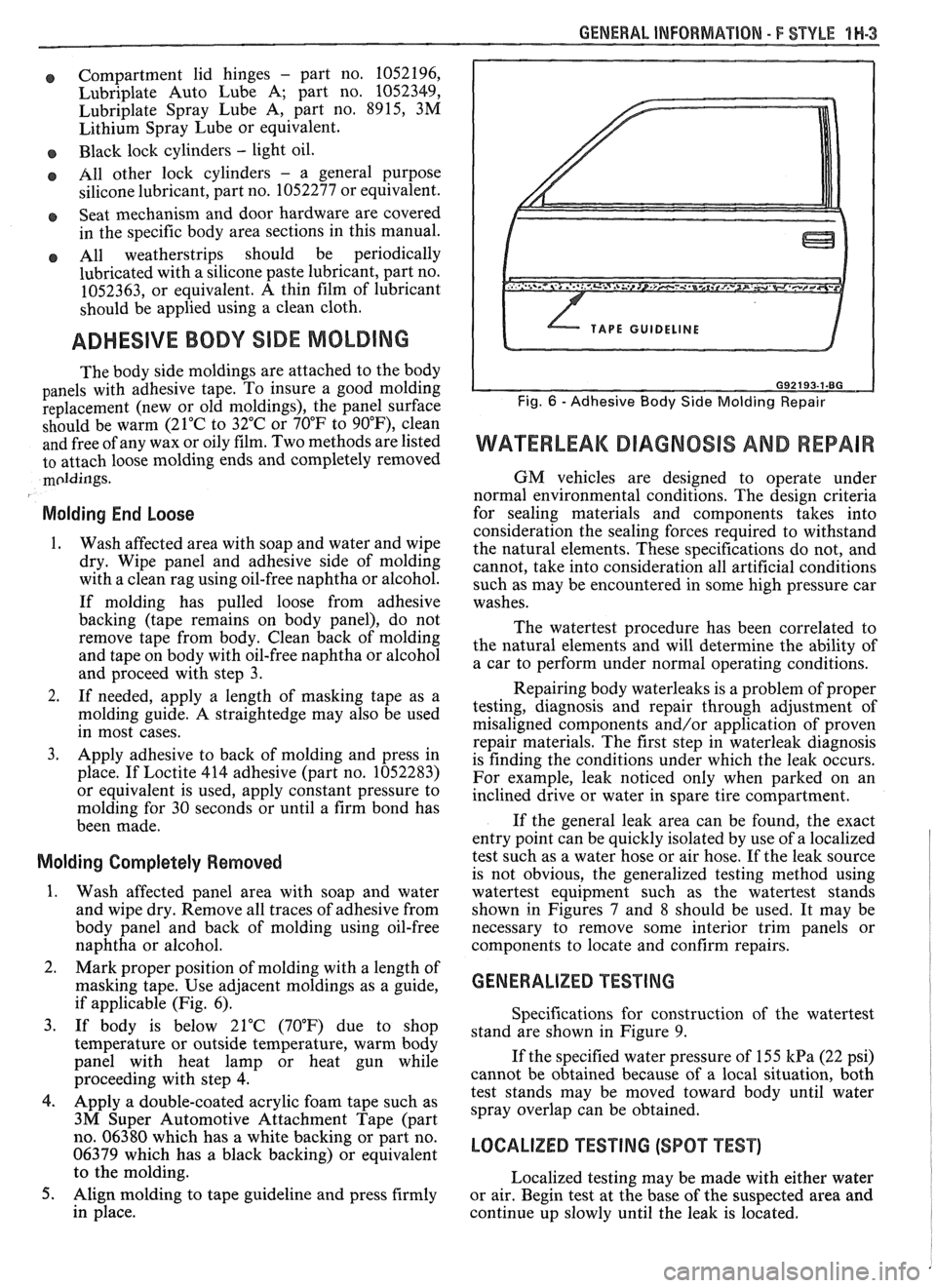
if applicable (Fig. 6).
3. If body is below 21°C (70°F) due to shop
temperature or outside temperature, warm body
panel with heat lamp or heat gun while
proceeding with step
4.
4. Apply a double-coated acrylic foam tape such as
3M Super Automotive Attachment Tape (part
no. 06380 which has a white backing or part no.
06379 which has a black backing) or equivalent
to the molding.
5. Align molding to tape guideline and press firmly
in place.
WATERLEAK DIAGNOSIS AND REPAIR
GM vehicles are designed to operate under
normal environmental conditions. The design criteria
for sealing materials and components takes into
consideration the sealing forces required to withstand
the natural elements. These specifications do not, and
cannot, take into consideration all artificial conditions
such as may be encountered in some high pressure car
washes.
The watertest procedure has been correlated to
the natural elements and will determine the ability of
a car to perform under normal operating conditions.
Repairing body waterleaks is a problem of proper
testing, diagnosis and repair through adjustment of
misaligned components and/or application of proven
repair materials. The first step in waterleak diagnosis
is finding the conditions under which the leak occurs.
For example, leak noticed only when parked on an
inclined drive or water in spare tire compartment.
If the general leak area can be found, the exact
entry point can be quickly isolated by use of a localized
test such as a water hose or air hose. If the leak source
is not obvious, the generalized testing method using
watertest equipment such as the watertest stands
shown in Figures
7 and 8 should be used. It may be
necessary to remove some interior trim panels or
components to locate and confirm repairs.
GENERALIZED TESTING
Specifications for construction of the watertest
stand are shown in Figure 9.
If the specified water pressure of 155
kPa (22 psi)
cannot be obtained because of a local situation, both
test stands may be moved toward body until water
spray overlap can be obtained.
LOCALIZED TEST lNG (SPOT TEST)
Localized testing may be made with either water
or air. Begin test at the base of the suspected area and
continue up slowly until the leak is located.
Page 1736 of 1825
REAR QUARTERS - F STYLE 8H-1
SECTION 6H
REAR QUARTERS
NOTICE: The anti-theft label found on some major sheet metal, engines, and transmissions must be masked
prior to painting, rustproofing, undercoating, etc. The mask
must be removed following the above operations.
Failure to keep the label clean and readable may result in liability for violation of Federal Vehicle Theft Prevention
Standard, and subject the vehicle owner to possible suspicion that the part was stolen.
CONTENTS
Quarter Trim .................................................... 6H- 1
Lower Trim Finishing Panel ....................... 6H- 1
Body Lock Pillar Trim Finishing
Panel
., ....................................................... 6H- 1
Upper Trim Finishing Panel Insert ............. 6H- 1
....................................................... Speakers 6H- 1
Lift Window Upper Finishing
Molding
..................................................... 6H-2
....................... Upper Trim Finishing Panel 6H-2
QUARTER TRlM
QUARTER LOWER TRlM FINISHING PANEL
Removal and Installation (Fig. 1)
Remove body lock pillar finishing panel (Fig. 3).
Remove rear
seatback lock striker.
Remove retaining screw in rearward area of
quarter lower trim panel.
Remove rear screws from sill plate and carpet
retainer (Fig.
2).
Grasp quarter lower trim panel with hand; then
pull forward and down to disengage from
pinchweld flange at weatherstrip and quarter
upper trim finishing panel.
Remove seat belt through slot in trim panel.
Remove quarter lower trim finishing panel from
car by lifting up on rear portion of sill plate and
carpet retainer; then pull quarter trim rearward.
To install, place panel retaining slots under
quarter upper trim panel and apply upward
pressure to secure.
Position panel assembly to body. Thread lap and
shoulder belt through respective slots in panel.
Install attaching screws to secure panel to body.
Replace all previously removed components.
BODY LOCK PILLAR TRlM FINISHING PANEL
Removal and lnstallation (Fig. 3)
1. Remove trim panel attaching screws.
2. Using trim removing tool J-24595B, BT-7323A
or equivalent, carefully disengage nylon fasteners
that retain body lock pillar panel to quarter upper
trim finishing panel.
3. To install, reverse removal procedures. Spare
Tire Cover Trim Finishing
Panel
........................................................ 6H-3
Rear Stowage Compartment Box
Assembly
................................................... 6H-4
Luggage Shade Cover Assembly
................. 6H-4
Exterior Moldings
........................................... 6H-6
Fuel Tank Filler Door and Pocket
Assembly
....................................................... 6H-7
Spoiler Extension
............................ .. ........... 6H-7
QUARTER UPPER TRlM FINISHING PANEL
INSERT
Removal and Installation (Fig. 4)
1. Remove coat hook.
2. Grasp panel insert with hand and pull upward to
disengage retainers from cutout slots in quarter
upper trim finishing panel (Fig. 4).
3. To install, reverse removal procedures.
REAR QUARTER SPEAKERS
The rear quarter speakers are installed to a
speaker retainer. The retainer and speaker are then
attached to the quarter inner panel by screws.
Standard Speakers
Remove or Disconnect
1. Quarter upper trim finishing panel insert
2. Screws securing speaker retainer
3. Disconnect electrical
connector from speaker
4. Speaker
Install or Connect
1. Speaker to body
2. Electrical connector
3. Screws securing speaker to retainer
4. Quarter upper trim finishing panel insert
Subwoofer Speakers (2FS/FW/FX Styles)
Remove or Disconnect (Fig. 5)
1.
Quarter upper trim finishing panel insert (Fig. 4)
2. Body lock pillar trim finishing panel (Fig. 3)
3. Two rear screws from carpet retainer (Fig.
2)
4.
Quarter lower trim finishing panel
Page 1737 of 1825
661-2 REAR QUARTERS - F STYLE
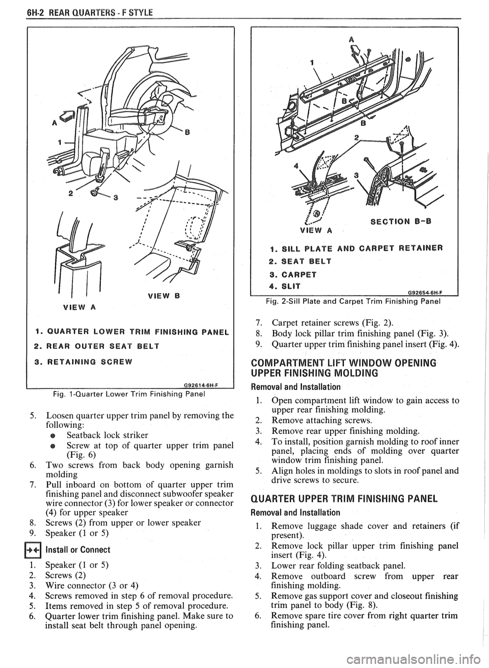
"1 QUARTER LOWER TRIM FINISHING PANEL
2. REAR OUTER SEAT BELT
3. RETAINING SCREW
Fig. I-Quarter Lower Trim Finishing Panel
5. Loosen quarter upper trim panel by removing the
following:
e Seatback lock striker
@ Screw at top of quarter upper trim panel
(Fig. 6)
6. Two screws from back body opening garnish
molding
7. Pull inboard on bottom of quarter upper trim
finishing panel and disconnect subwoofer speaker
wire connector (3) for lower speaker or connector
(4) for upper speaker
8. Screws (2) from upper or lower speaker
9. Speaker (1 or 5)
Install or Connect
1. Speaker (1 or 5)
2. Screws (2)
3. Wire connector
(3 or 4)
4. Screws removed
in step 6 of removal procedure.
5. Items removed in step 5 of removal procedure.
6. Quarter lower trim finishing panel. Make sure to
install seat belt through panel opening.
'@ ,:'
{.-J SECTION B-I)
VIEW A
I. SILL PLATE AND CARPET RETAINER
4. SEAT BELT
9. CARPET
Fig. 2-Sill Plate and Carpet Trim Finishing Panel
7. Carpet retainer screws (Fig. 2).
8. Body lock pillar trim finishing panel (Fig. 3).
9. Quarter upper trim finishing panel insert (Fig. 4).
COMPARTMENT LIFT WINDOW OPENING
UPPER
FINISHING MOLDING
Removal and lnstallation
1. Open compartment lift window to gain access to
upper rear finishing molding.
2. Remove attaching screws.
3. Remove rear upper
finishing molding.
4. To
install, position garnish molding to roof inner
panel, placing ends of molding over quarter
window trim finishing panel.
5. Align holes in moldings to slots in roof panel and
drive screws to secure.
QUARTER UPPER TRIM FINISHING PANEL
Removal and Installation
1. Remove
luggage shade cover and retainers (if
present).
2. Remove
lock pillar upper trim finishing panel
insert (Fig. 4).
3. Lower
rear folding
seatback panel.
4. Remove outboard screw from upper rear
finishing molding.
5. Remove gas support cover and closeout finishing
trim panel to body (Fig.
8).
6. Remove spare tire cover from right quarter trim
finishing panel.