1988 PONTIAC FIERO lights
[x] Cancel search: lightsPage 1512 of 1825
THEFT DETERRENT SYSTEM: PASSKEY I a
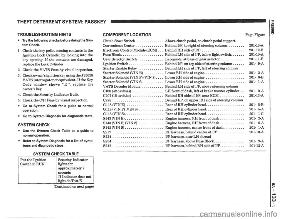
TROUBLESHOOTING HINTS COMPONENT LOCATION
Try the following checks before doing the Sys-
tem Check.
1. Check the key pellet sensing contacts in the
Ignition Lock Cylinder by looking into the
key opening. If the contacts are damaged,
replace the Lock Cylinder.
2. Check the VATS Fuse by visual inspection.
3. Check owner's ignition key using the 535628
VATS Interrogator or equivalent.
If the Key
Code window shows "E", replace the
owner's key.
4. Check the Security Indicator Bulb.
5. Check the
CIH Fuse by visual inspection.
Go to System Check for a guide to normal
operation.
Go to System Diagnosis for diagnostic tests.
SYSTEM CHECK
Use the System Check Table as a guide to
normal operation.
r Refer to System Diagnosis for a list of symp-
toms and diagnostic steps.
Clutch Start Switch .............. Above clutch pedal, on clutch pedal support
Convenience Center
.............. Behind IIP, to right of steering column. ........
Electronic Control Module (ECM) ... Behind RN side of IIP ......................
Fuse Block. ..................... Behind LH side of IIP, below light switch. ......
Gear Selector Switch ............. In console, at base of gear selector ............
Ignition Switch. ................. Behind IIP, on top side of steering column ......
Starter Enable Relay ............. Behind LH side of IIP, left of steering column
Starter Solenoid (VIN E)
.......... Lower RH side of engine ....................
Starter Solenoid (VIN F) (VIN 8). ... Lower RH side of engine ....................
Starter Solenoid (VIN S) .......... Lower RN side of engine ....................
VATS Decoder Module. ........... Behind LH side of IIP, above steering column
Cl00 (42 cavities) ................ LH front of dash, left of brake master cylinder ..
C207 (15 cavities) ................ Behind RN side of IIP, near ECM .............
6228. .......................... Behind IIP, on upper RH side of steering column
6118 (VIN
E) ................... Rear of RN cylinder head. ...................
6118 (VIN F) (VIN 8) ............. Rear of RH cylinder head. ...................
6118 (VIN S) .................... Rear of RN cylinder head. ...................
S143 (VIN E) .................... Engine harness, RR front of dash. ............
S143 (VIN F) (VIN 8) ............. Engine harness, RN front of dash. ............
S143 (VIN S) .................... Engine harness, center front of dash. ..........
S217. .......................... IIP harness, behind center of IIP. .............
S224. .......................... IIP harness, near LH shroud
S234. .......................... I/P harness, above Fuse Block. ...............
S242. .......................... IIP harness, behind RH side of IIP ............
SYSTEM CHECK TABLE
(Continued on next page)
Put
the Ignition
Switch in RUN
R aJ XI
Page-Figure u
Security Indicator
lights for
approximately 2
seconds If Indicator does not
light do Test E
Page 1516 of 1825
THEFT DETERRENT SYSTEM: PASSKEY
3. A number from 1 to 15 will appear in the
window designating the electrical code of
the key.
4. Cut a new key having the electrical code
ed from the 535628 Interrogator.
5. Start the engine using the new key to insure
that the key is correct both mechanically
and electrically.
Key Replacement (No Spare Key Available)
1. If the Ignition Key is lost and there is no
spare key, determine the mechanical code
from the code on the Ignition Key Lock
CyE
inder. The code may also be det
the dealer invoice for the car, or from the
Chewolet Zone Office.
2. Cut anew key to this mechanical code. Use a
blank PASSKEY test key which has no
resistance pellet. This key will be used to
operate the Ignition Switch for the remain-
ing steps.
3. Remove the hush panel under the steering
column and disconnect
C281 (two-cavity
connector leading into the steering column).
4. Insert the male half of the connector into the
female
pigtail connector from the 535628
Interrogator.
5. Set the Key Code Selector on the
Hnter-
rogator (535628 or equivalent) to "1 ".
6. Attempt to start engine using the key made
in step 2.
r If engine starts, the Key Code Selector is set
to the correct electrical code. Cut a new key
having this electrical code. The new key will
be customer's replacement key.
If engine does not start, turn Ignition
Switch to OFF, then turn the Key Code
Selector to the next higher position. Wait
four minutes and attempt to start the engine
using the new electrical code. Use the 4-min-
ute Timer on the 535628 Interrogator to
indicate the 4-minute interval. Start the
Timer by depressing the "Start" rocker
switch. The red indicator
will turn off at the
end of a four minute interval.
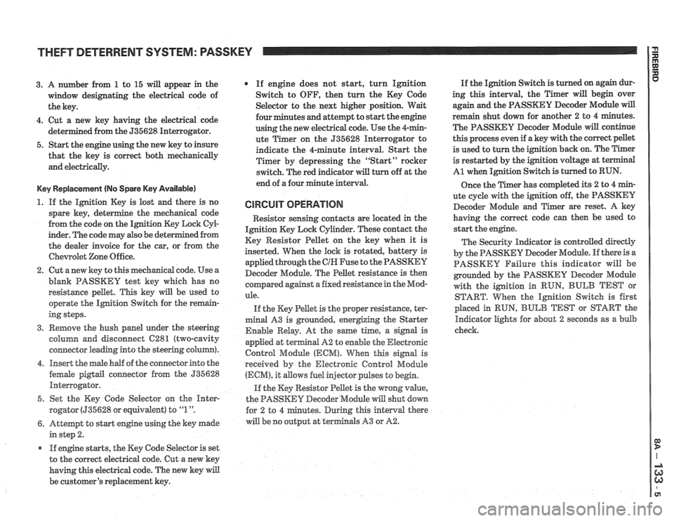
CIRCUIT OPERATION
Resistor senshg contacts are located in the
Ignition Key Lock Cylinder. These contact the
Key Resistor Pellet on the key when it is
inserted. When the lock is rotated, battery is
applied through the
CIH Fuse to the PASSKEY
Decoder Module. The Pellet resistance is then
colnpared against a fixed resistance in the Mod-
ule.
If the Key Pellet is the proper resistance, ter-
minal A3 is grounded, energizing the Starter
Enable Relay. At the
same time, a signal is
appfied at terminal A2 to enable the Electronic
Control Module
(ECM). When this signal is
received by the Electronic Control Module
(ECM), it allows fuel injector pulses to begin.
If the Key Resistor Pellet is the wrong
value,
the PASSKEY Decoder Module will shut down
tes. During this interval there
will be no output at terminals A3 or
A2.
If the Ignition Switch is turned on again dur-
ing this interval, the Timer will begin over
again and the PASSKEY Decoder Module
will
remain shut down for another 2 to 4 minutes.
The PASSKEY Decoder Module will continue
this process even if a key with the correct pellet
is used to turn the ignition back on. The Timer
is restarted by the ignition voltage at
t
A1 when Ignition Switch is turned to RUN.
Once the Timer has completed its
2 to 4 min-
ute cycle with the ignition off, the PASSKEY
Decoder Module and Timer are reset. A key
having the correct code can then be used to
start the engine.
The Security Indicator is controlled directly
by the PASSKEY Decoder Module. If there is a
PASSKEY Failure this indicator will be
grounded by the PASSKEY
Decoder Module
with the ignition in RUN,
BULB TEST or
START. When the Ignition Switch is first
placed in
RUN, BULB TEST or START the
Indicator lights for about 2 seconds as a bulb
check.
Page 1530 of 1825
AUTOMATIC DAY-NIGHT MIRROR
TROUBLESHOOTING MINTS
Try the following checks before doing the
System
Gheck.
1. Check TURN BIU Fuse and the Gear Selec-
tor Switch (Automatic Transmission) or
Back
Up Switch (Manual 'L'ransfission) by
checking operation of the Back Up Lights.
2. Check GAGES Fuse by observing the
BRAKE Indicator with the Park Brake
applied and
IMtion Switch in RUN.
@ Go to System Gheck for a guide to normal
operation.
Go to System Diagnosis for diagnostic tests.
Use the System Check Table as a guide to
normal operation.
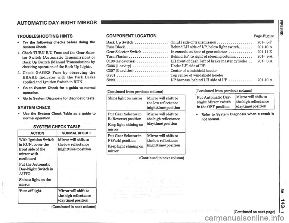
SYSTEM CHECK TABLE
nighttime) position
t the Automatic
ay-Night Switch
in
Shine a light on the
COMPONENT LOCATION Page-Figure
.................. Back Up Switch ................. On LN side of transIlnission 201- 8-F
...... Fuse Block. ..................... Behind LN side of IIP, below light switch. 201-10-A
............ Gear
Selector Switch ............. In console, at base of gear selector 201-11-E
........ 'Turn Flasher .................... Behind
PIP, to right of steering column. 201-
9-A
.. C100 (42 cavities) ................ LR front of dash, left of brake master cylinder 201-
0-A
6305 (1 cavity) .................. Under LH side of IIP
C307 (3 cavities) ................. Center of windshield header
6201
.......................... Top center of windshield header
............ S229. .......................... IIP harness, behind LW side of IIP 201-10-A
(Continued from previous column)
(Continued in next co (Continued
from previous column)
Refer to System Diagnosis when a result is
not normal.
(Continued in next colum)
(Continued on next page)
Page 1531 of 1825
AUTOMATIC DAY-NIGHT MIRROR
(Continued from previous page)
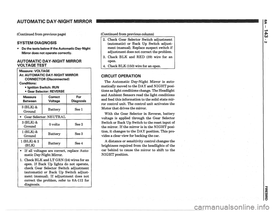
SYSTEM DIAGNOSIS
0 Do the tests below if the Automatic Day-Night
Mirror does not operate correctly.
AUTOMATIC DAY-NIGHT MIRROR
VOLTAGE TEST
CONNECTOR (Disconnected)
1. Check BLK and LT GRN (24) wires for an
open. If Back Up lights do not operate,
check Gear Selector Switch adjustment
(automatic) or Back Up Switch
adjust-
:Continued from previous column)
2. Check Gear Selector Switch adjustment
(automatic) or Back Up Switch adjust-
ment (manual). Replace suspect switch if
adjustment does not correct the problem.
3. Check BLK and RED (39) wire for an
open.
4. Check BLK (150) wire for an open.
CIRCUIT OPERATION
The Automatic Day-Night Mirror is auto-
matically moved to the DAY and NIGHT posi-
tions as light conditions change. The Headlight
and Ambient Sensors read the light conditions
and feed this information to the solid state
mir-
ror control unit. The control unit activates the
Motor that drives the mirror.
With the Gear Selector
in Reverse, battery
voltage is applied through the Gear Selector
Switch or Back Up Switch to the reset input of
the mirror. If the mirror is in the NIGHT posi-
tion,
it changes to the DAY position. This pro-
vides a clear view for backing the car.
A distance or sensitivity control changes the
brightness required from the headlights of the
car behind to cause the
mirror to shift to the
NIGHT position.
Page 1546 of 1825
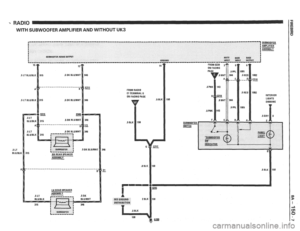
RADIO
WITH SUBWOOFER AMPLIFIER AND WITHOUT UK3
INTERIOR LIGHTS
- -
Page 1548 of 1825
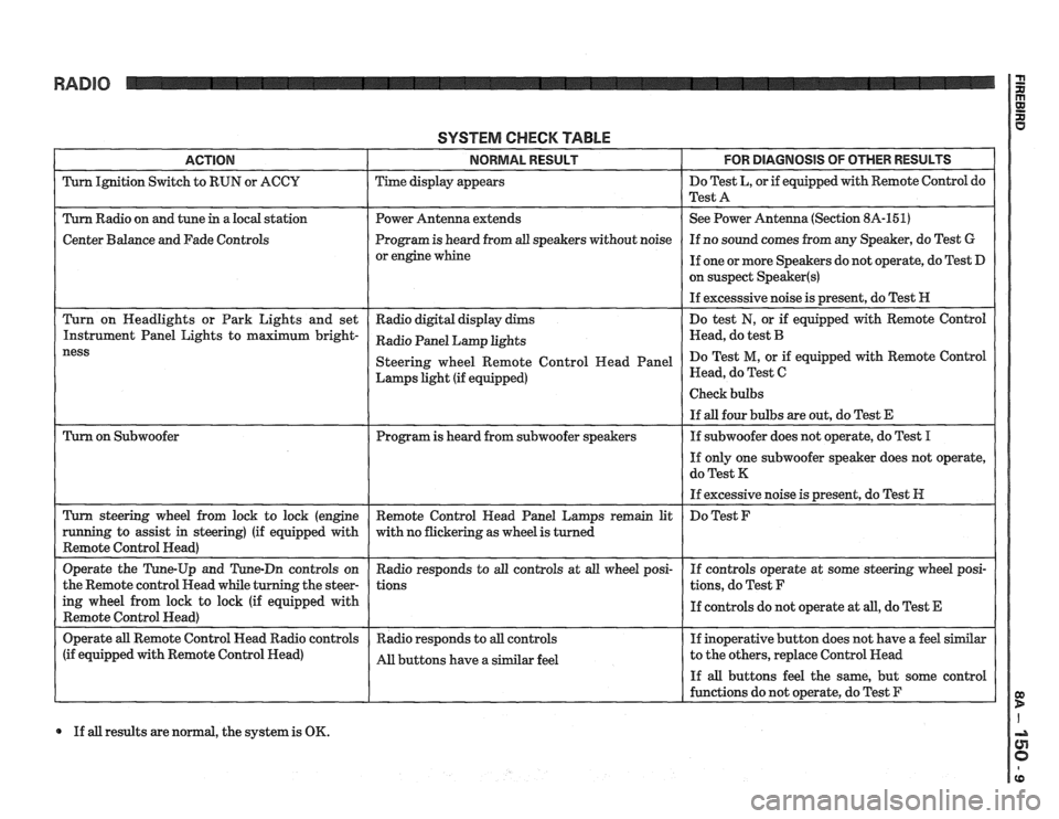
RADIO
SYSTEM CHECK TABLE
ACTION NORMAL RESULT FOR DlAGNOSlS OF OTHER RESULTS
Turn Ignition Switch to RUN or ACCU Time display appears Do
Test L, or if equipped with Remote Control do
Test A
Turn Radio on and tune
in a local station Power Antenna extends See
Power Antenna (Section 8A-151)
Center Balance and Fade Controls Program
is heard from all speakers without noise If
no sound comes from any Speaker, do Test G
or engine whine
If one or more Speakers do not operate, do Test D
on suspect
Speaker(s)
If excesssive noise is present, do Test H
Turn on Headlights or Park Lights and set
Radio digital display dims Do
test
N, or if equipped with Remote Control
Instrument Panel Lights to maximum
bright- Radio Panel Lamp khts Head, do test B
Lamps light (if equipped) Head,
do Test C
If all results are normal, the system is OK.
Page 1550 of 1825
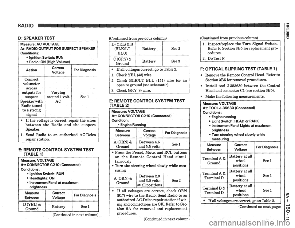
D: SPEAKER TEST (Continued from previous column)
At: RADIO OUTPUT FOR SUSPECT SPEAKER
Ignition Switch: RUN
o an authorized AC-Delco
E: REMOTE CONTROL SYSTEM TEST
(TABLE
1)
Measure: VOLTAGE
At: CONNECTOR C210 (Connected)
Conditions: Ignition Switch: RUN
. Headlights: ON
I r Instrument Panel at maximum I brightness
I Measure I I For Diagnosis ( Between
I & I Battery I See 1 1 Ground I I I I
(Continued in next column)
D (YEL) & B
(BLKILT Battery See 2
BLU)
(GRY) & Battery
Ground See 3
If all voltages correct, go to Table
2.
1. Check YEL (43) wire.
2. Check BLKILT BLU (151) wire for an
open to ground (see schematic).
3. Check GRY
(8) wire.
E: REMOTE CONTROL SYSTEM TEST
(TABLE 2)
At: CONNECTOR 6210 (Connected)
Condition:
Measure
Between
I tz I For Diagnosis
1 I - I
A (ORN) & Between 4.5
Ground and 5.5 volts See 1
Press
the Preset, Mute, and RCL buttons
on the Remote Control
Head simul-
taneously
r Turn the steering wheel slowly while mea-
Between 2.0
at
all positions
If
all voltages are correct, check ORN
(917) wire to the Radio. Send Radio to an
authorized AC-Delco repair station if wir-
ing and connections are OK. Refer to Sec-
tion
9A for removal and replacement
~rocedures. ---- - -
(Continued in next column) (Continued from
previous
column)
Refer to Section 3B5 for replacement pro-
cedures.
2. DoTest F.
F: OPTlCAL SLlPRlNG TEST (TABLE 1 )
e Remove the Remote Control Head. Refer to
Section 3B5 for removal procedures.
r Install tool 5-353630 between the Control
Head and connector
C1 (see section 3B5).
Make the following measurements.
At: TOOL 5-35630 (Connected)
Engine running
0 Light Switch: MEAD or PARK
0 lnstrument Panel Lights at maximum
@ If all voltages are correct, go to Table 2.
(Continued on next page)
Page 1558 of 1825
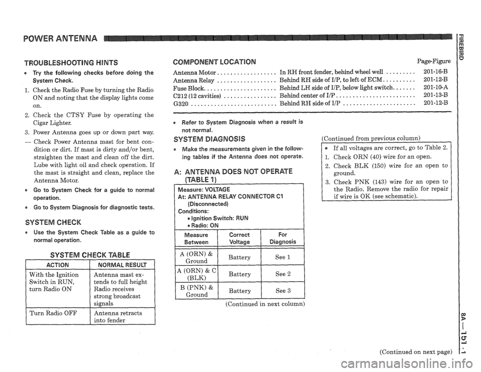
POWER ANTENNA
TROUBLESHOOTING HINTS
r Try the following checks before doing the
System Check.
1. Check the Radio Fuse by turning the Radio
ON and noting that the display lights come
on.
2. Check the CTSY Fuse by operating the
Cigar Lighter.
3. Power Antenna goes up or down part way
- Check Power Antenna mast for bent con-
dition or dirt. If
mast is dirty and/or bent,
straighten the mast and clean off the dirt.
Lube with light oil and check operation. If
the mast is straight and clean, replace the
Antenna Motor.
c Go to System Check for a guide to normal
operation.
e Go to System Diagnosis for diagnostic tests.
SYSTEM CHECK
a Use the System Check Table as a guide to
normal operation.
SYSTEM CHECK '6ABLE
Radio receives
COMPONENT LOCATION Page-Figure
................. ......... Antenna Motor. In RW front fender, behind wheel well 201-16-B
.................. .......... Antenna Relay Behind RN side of I/P, to
left of ECM 201-12-B
..................... ...... Fuse Block. Behind LR side
of UP, below light switch. 201-10-A
........................ ................ 6212 (12 cavities) Behind center of I/P 201-13-B
...................... .......................... 6320 Behind RH side of IIP 201-12-33
Refer to System Diagnosis when a result is
not normal.
SYSTEM DlAGNOSlS
o Make the measurements given in the follow-
ing tables if the Antenna does not operate.
A: ANTENNA DOES MOT OPERATE
(TABLE 1)
At: ANTENNA RELAY CONNECTOR 61
(Continued in next column) Continued
from previous
column)
2. Check BLK (150) wire for an open to
ground.
3. Check PNK (143) wire for an open to
the Radio. Remove the radio for repair
(Continued on next page)