1988 PONTIAC FIERO check engine light
[x] Cancel search: check engine lightPage 968 of 1825
DRIVEABILITY AND EMISSIONS - FUEL INJECTION 6E-7
On engines that can be monitored in the open
mode, it allows certain parameters to be obtained
without changing the engine operating
characteristics. The parameters capable of being read
vary from engine family to engine family. Most
"Scan" tools are programmed so that the system will
go directly into the special mode
if the "open" mode is
not available.
ALDL (7 OK, or Special) Mode
(not used on
all engines)
In this mode, all information incorporated into a
specific
engine and ECM is obtainable. However, in
this mode the system operating characteristics are
modified as follows.
@ "Closed Loop" timers are bypassed
EST (spark) is advanced
@ IAC will control engine idle to 1000 rpm I
50 rpm (if applicable)
@ On some engines, canister purge solenoid will
be enabled
@ P/N restrict functions will be disabled.
Factory Test (Back-up or 3.9 K) Mode
(TBI, Port)
In this mode, the ECM is operating on the fuel
back-up logic and is calibrated by the Calpak or Mem-
cal. These are used to control the fuel delivery
if the
ECM fails. This mode verifies that the back-up feature
is OK. The parameters that can be read on a
"Scan"
tool in this mode are not of much use for service.
"SCAN" TOOL LIMITATIONS AND USE
The "Scan" tool allows a quick check of sensors
and switches which are inputs to the ECM. However,
on some applications the data update rate makes the
tool less effective as a voltmeter when trying to detect
an intermittent which lasts for a very short time.
However, the "Scan" tool allows one to manipulate
wiring harnesses or components under the hood while
observing the "Scan" readout. This helps in locating
intermittents with the engine not running.
intermittent Conditions
for a period of time to see if there is any change in the
readings that indicates intermittent operation.
The "Scan" tool is also a useful and quick way of
comparing operating parameters of a poorly operating
engine with a known good one. For example;
A sensor
may shift in value but not set a code. Comparing with
a known good vehicle may uncover the problem.
The "Scan" tool has the ability to save time in
diagnosis and prevent the replacement of good parts.
The key to using the "Scan" tool successfully for
diagnosis lies in the technician's ability to understand
the system he is trying to diagnose as well as an
understanding of the "Scan" tool's limitations.
Therefore, the technician should read the tool
manufacturer's operating manual to become familiar
with the operation. The following information will
describe most of the "Scan" tool positions and how
they can be helpful in diagnosis.
"SCAN" TOOL POSITIONS
The following positions may not be applicable to
all engines. See the facing page
of the diagnostic
circuit check for a particular engine to decide which
positions apply to that engine.
Mode
Check with the manufacturer to determine what
the function of this mode is. In most cases it allows the
user to place the ECM in different operating modes.
Injector Pulse Width
In this position, the reading is given in
milliseconds, which is the
"ON" time that the ECM is
commanding to the
injector(s1.
Closed LoopIOpen Loop
This position will indicate whether the engine
control system is operating in "Open Loop" or "Closed
Loop". Most systems go "Closed Loop" after a certain
amount of running time, when coolant temperature is
high enough, and the oxygen sensor becomes active.
Exhaust (RichILean Indicator)
The "Scan" tool is helpful in cases of intermittent
This indicates the O2 sensor voltage at the instant operation' The can be in and observed that the data stream is sampled. If voltage is less than
while driving the vehicle under the condition where
350 mv, the value will be lean. If above 550 mv, a rich the light comes "ON" momentarily, or the engine exhaust is indicated. driveability is poor momentarily. If the problem
seems to be related to certain areas that can be
Codes checked on the "Scan" tool, then those are the
positions that should be checked while driving the
This will display any trouble codes stored in the
vehicle. If there does not seem to be any correlation
ECM memory. between the problem and any specific circuit, the
"Scan" tool can be checked on each position, watching
Page 970 of 1825
DRIVEABILITY AND EMISSIONS - FUEL INJECTION 6E-9
ParWNelatral Switch IAC (Idle Air Control)
The indication in this mode may vary with This system is used to control engine idle speed to
manufacturer so the type of reading for a particular the desired rpm, for different operating conditions. In
tool should be checked in the operator's manual. The this mode, the numbers will indicate the position to
important thing is that the the reading changes state which
the ECM has moved the valve pintle. The ECM
(switches) when the gear selector is moved from moves
the IAC in counts, or steps, and the number of
paridneutral to drive or reverse. these counts are displayed on a "Scan" tool.
"Trque Convertor Clutch (TCC)
In this position, the tool will indicate when the
TCC has been commanded by the ECM to turn "ONJ'.
This does not necessarily mean that the clutch was
engaged but only that the
ECM grounded the circuit
internally. The best way to determine if the clutch has
engaged is to monitor engine rpm when the TCC
comes "ON".
EGR (Duty Cycle)
The EGR system uses a valve to feed a small
amount of exhaust gas back into the intake manifold
to control formation of NO,. Like all ECM outputs, the
"Scan" tool only indicates that the ECM has
commanded the function, and does not indicate that
the function has really happened.
EGR Position
This indicates the position of the EGR pintle.
Integrator and Block Learn
Normal readings for these positions are around
128. If higher, it indicates that the ECM is adding fuel
to the base fuel calculation because the system is lean,
and if the numbers are below 128, the ECM is taking
out fuel from the base calculation because the system
is rich. The integrator gives short term corrective
action, while the block learn portion (which is a long
term correction) will only change if the integrator has
seen a condition which lasts for a calibrated period of
time.
Block Learn Multiplier (BLM) Cell - or -
Block Learn Memory (BLM)
There are up to sixteen different cells,
corresponding to ranges of rpm and engine load
(indicated by MAF or MAP signals), and other
conditions, such as
A/C or P/N switch "ON" or "OFF",
etc. The ECM learns how much adjustment is needed
in each cell, and retains it in memory, so that the
adjustment will immediately be made when the
engine operates in that cell (or
rpmlload range). This
parameter will display what cell the ECM is currently
using for the fuel calculation.
Desired RPM
This indicates the rpm to which the ECM is trying
to control the idle.
Shift Light
This displays "yes" when the ECM is commanding
the shift light to turn "ON".
PPSW (Pump Prime Switch)
This is the voltage on the fuel pump feed circuit.
The ECM will adjust fuel injector base pulse width
from this voltage value rather than from battery
voltage.
NC Request
The state of the A/C signal line to the ECM is
shown. It should read "yes" whenever the
IVC is
requested.
NC Clutch
"ON" is displayed when the ECM has commanded
the
A/C clutch "ON".
Knock Retard
This indicates the number of degrees the ECM is
retarding the electronic spark timing (EST).
Knock Signal
This displays a "yes" when knock is detected by
the ECM, and a "no" when knock is not detected.
Battery Voltage
This displays the battery voltage detected at the
ECM ignition input.
Fan
"ON" is displayed when the cooling fan has been
commanded "ON".
Page 991 of 1825

700-R4-2 HYDRAULIC DIAGNOSIS
R - Reverse allows the vehicle to be operated in
a rearward direction.
N - Neutral allows the engine to be started and
operated without driving the vehicle. If necessary this
position may be selected if the engine must be restarted
with the vehicle moving.
D - Overdrive is used for all normal driving
conditions. It provides four gear ratios plus converter
clutch operation. Downshifts are available for safe
passing by depressing the accelerator.
D - Drive position is used for city traffic, hilly
terrain, and trailer towing. It provides three gear
ranges. Again, downshifts are available by depressing
the accelerator.
2 - Manual second is used to provide acceleration
and engine braking. This range may be selected at any
vehicle speed.
1 - Manual Lo is used to provide maximum
engine
brlking. This range may also be selected at any
vehicle speed.
DIAGNOSIS INFORMATION
ROAD TEST PROCEDURE
e Perform the road test following the sequence
given
e MPH (KPH) shift points will vary with actual
throttle position and driver habits
e Compare the results of the test with speed shift
chart information. Use these results with the
diagnosis information contained in this
Automatic Transmission Hydraulic Diagnosis
Section to evaluate the transmission.
e This test should only be performed when traffic
and road conditions permit
e Observe all traffic safety regulations
Drive and Reverse Engagement Shift Check
1. Start engine
2. Depress brake pedal
3. Move gear selector:
- "Park" (P) to "Reverse" (R)
- "Reverse" (R) to "Neutral"
(N) to "Drive" (D)
Gear selections should be immediate and
not harsh.
Upshifts and Torque Converter Clutch (TCC)
Apply (Figure
2)
With gear selector in "Overdrive" (D)
1. Accelerate using a steady increasing throttle
pressure
2. Note the shift speed point gear engagements for:
- 2nd gear
- 3rd gear
- Overdrive
3. Note the speed shift point for TCC apply. This
should occur while in third gear or overdrive. If
the apply is not noticed, refer to the Preliminary
Torque Converter Clutch Diagnosis information
contained in this section of the Service Manual.
Important
The torque converter clutch will not engage if
engine coolant has not reached a minimum
operating temperature of approximately 54°C
(1 30°F).
Part Throttle Downshift
At vehicle speeds of 40-55 MPH (64-88
KPH) quickly depressed the accelerator to
a half open position and observe:
- TCC releases
- Transmission downshift to 3rd gear
immediately
Full Throttle (Detent) Downshift
At vehicle speeds of 48-55 MPH (77-88
KPH) quickly depress the accelerator to a
wide open position and observe:
- TCC releases
- Transmission downshifts to 2nd gear
immediately
Manual Downshift
1. At vehicle speeds of 40-55 MPH (64 to 88 KPH)
release the accelerator pedal while moving the
gear selector to "Third" gear (D) and observe:
- TCC release
- Transmission downshift to 3rd gear should
be immediate
- Engine should slow vehicle down
2. Move gear selector to "Overdrive" and accelerate
to 40-45 MPH (64-72 KPH). Release the
accelerator pedal while moving the gear selector
to "Second" gear (2) and observe.
- TCC release
- Downshift to second gear should be
immediate
- Engine should slow vehicle down
3. Move gear selector to "Overdrive" (D) and
accelerate to 25 MPH (40 KPH). Release the
accelerator pedal while moving the gear selector
to "First" gear (1) and observe:
- TCC release
- Transmission downshift to 1st gear should
be immediate
- Engine should slow vehicle down
Coastdown Downshift
1. With the gear selector in "Overdrive" (D)
accelerate to 4th gear with TCC applied.
2. Release the accelerator pedal and lightly apply
the brakes to observe:
- TCC release
- Shift points for downshifts.
Manual Gear Range Selection
MANUAL THIRD (D)
1. With vehicle stopped, place gear selector in
"Third" (D) and accelerate to observe:
Page 1050 of 1825
TORQUE CONVERTER CLUTCH (TCC)
DIAGNOSIS
To properly diagnose the Torque Converter
Clutch (TCC) system, perform all electrical
testing first and then the hydraulic testing. Refer
to the Torque Converter Section
6E2-C8 for
additional information.
The TCC is applied by fluid pressure which is
controlled by a solenoid located inside the Automatic
Transmission assembly. The solenoid is energized or
released by making or breaking an electrical circuit
through a combination of switches and sensors.
TCC Electrical Diagnosis
e For electrical diagnosis of TCC, refer to the
specific vehicle section in Section
8A, Electrical
Diagnosis.
e For diagnosis of emission control related
components of TCC, Refer to the specific section
of
6E, Driveability and Emissions.
e For the diagnosis of TCC Hydraulic Controls,
refer to the Procedure and Wiring Diagrams
provided in this section.
Functional Check Procedure
rn Inspect
1. Install a tachometer
2. Operate the vehicle until proper operating
temperature is reached
3. Drive vehicle at 50-55 mph (80-88 Km/h) with
light throttle (road load)
4. Maintaining throttle lightly touch the brake
pedal and check for a slight bump when the TCC
releases and a slight increase in engine RPM.
5. Release the brake, slowly accelerate and check for
a re-apply of the converter clutch and a slight
decrease in engine RPM.
Preliminary Checking Procedure
The purpose of the preliminary checking
procedure is to isolate external (electrical) problems
from internal (electrical or mechanical) ones.
Important
e Use only a scale type ohmmeter. High impedance
type ohmmeters and those with a digital readout
will not work.
e An ALCL scanner may be used to verify the
electrical circuit. Remember, a completed circuit
does not indicate that the solenoid will apply.
e Do not bench test using an automotive type
battery. Accidentally crossed wires will damage
the internal diodes of the TCC solenoid.
HYDRAULIC DIAGNOSIS 700-R4-61
External Controls
rn Inspect
e Connect voltmeter between transmission
connector and ground.
e Turn key "ON"
e If 0 or low voltage is found, refer to Sections 6E
and 8A for electrical diagnosis.
e If 12 volts are present at the connector, refer to
the TCC hydraulic diagnosis.
TORQUE CONVERTER EVALUATION
Torque Converter Stator
The Torque Converter Stator roller clutch can
have one of two different type malfunctions:
A. Stator Assembly freewheels in both
directions.
B. Stator Assembly remains locked up at all
times.
Condition A-Poor Acceleration Low Speed
The vehicle tends to have poor acceleration from
a standstill. At speeds above 30-35 mph (50-55
km/h),
the car may act normal. If poor acceleration is noted,
it should first be determined that the exhaust system
is not blocked, the engine timing is correct and the
transmission is in first
(1st) gear when starting out.
If the engine freely accelerates to high
r.p.m. in
"NEUTRAL" (N), it can be assumed that the engine
and exhaust system are normal. Checking for poor
performance in "Drive" and Reverse will help
determine if the stator is freewheeling at all times.
Condition B-Poor Acceleration High Speed
Engine r.p.m. and car speed limited or restricted
at high speeds. Performance when accelerating from a
standstill is normal. Engine may over-heat. Visual
examination of the converter may reveal a blue color
from over-heating.
If the converter has been removed, the stator
roller clutch can be checked by inserting a finger into
the splined inner race of the roller clutch and trying to
turn the race in both directions. The inner race should
turn freely clockwise, but not turn or be very difficult
to turn counterclockwise.
The Converter Should Be Replaced If:
e Leaks externally, such as at the hub weld area.
e Converter has an imbalance which cannot be
corrected. (Refer to Converter Vibration Test
Procedure).
e Converter is contaminated with engine coolant
containing antifreeze.
The Converter Should Not Be Replaced If:
e The oil has an odor, is discolored, and there is no
evidence of metal or clutch facing particles.
e The threads in one or more of the three converter
bolt holes are damaged.
- Correct with thread insert. (Refer to Section
6A).
Page 1121 of 1825
7A1-2 AUTOMATIC TRANSMISSION ON-VEHICLE SERVICE
Pitting
FLEXPLATE/TORQUE CONVERTER VIBRATION
TEST PROCEDURE
1. Start engine
2. With engine at idle speed and the transmission in
"Park"
(P) or "Neutral" (N), observe vibration.
3. Shut off engine.
Remove or Disconnect
e Flexplate cover attaching bolts
s Flexplate to torque converter attaching
bolts
e Rotate torque converter 120 (1/3 turn)
Install
or Connect
e Flexplate to torque converter attaching
bolts
- Torque bolts to 47 N.m (35 Ibs. ft.)
s Flexplate cover bolts
- Torque bolts to 6 N-m (53 lbs. in.)
4. Start engine and check for vibration. Repeat this
procedure un
ti1 the best possible balance is
obtained.
NOTICE: Some engine/transmission
combinations cannot be balanced in this manner
due to limited clearances between the torque
converter bolts and engine. Be sure bolts do not
bottom out in lug nuts or the torque converter
cover could be dented and cause internal damage.
FLUID LEAK DIAGNOSIS
The cause of most external leaks can generally be
located and repaired with the transmission in the car.
METHODS FOR LOCATING LEAKS
General Method
s Verify that the leak is transmission fluid.
a Thoroughly clean the suspected leak area.
s Operate the car for about 15 miles or until normal
operating temperatures are reached.
e Park the car over clean paper or cardboard.
s Shut off engine and look for fluid spots on paper.
a Make necessary repairs.
Powder Method
e Thoroughly clean the suspected leak area with
solvent.
a Apply an aerosol type powder (foot powder) to
the suspected leak area.
s Operate the car for about 15 miles or until normal
operating temperatues are reached.
s Shut off engine.
e Inspect suspected leak area and trace the leak
path through the powder to find the source.
a Make necessary repairs.
Dye And Black Light Method
A fluid dye and black light kit is available from
various tool manufacturers.
s Follow the manufacturer's recommendations for
the amount of dye to be used.
a Detect the leak with the black light.
e Correct cause of leak.
REPAIRING THE LEAK
Once the leak has been pinpointed and traced
back to its source, the cause of the leak must be
determined in order for it to be repaired properly. If a
gasket is replaced, but the sealing flange is bent, the
new gasket will not repair the leak. The bent flange
must be repaired also. Before attempting to repair a
leak, check to be sure that the following conditions are
correct as they may cause a leak.
Gaskets
s Fluid level/pressure is too high.
e Plugged vent or drain-back holes.
s Improperly torqued fasteners or dirty/damaged
threads.
a Warped flanges or sealing surface.
e Scratches, burrs or other damage to the sealing
surface.
e Damaged or worn gasket.
e Cracking or porosity of the component.
s Improper sealant used (where applicable).
Seals
e Fluid level/pressure is too high.
a Plugged vent or drain-back holes.
s Damaged seal bore (scratched, burred or nicked).
e Damaged or worn seal.
e Improper installation.
a Cracks in component.
e Manual or output shaft surface scratched, nicked
or damaged.
a Loose or worn bearing causing excess seal wear.
Possible Points of Oil Leak
I. Transmission/Transmission oil pan :
Attaching bolts not correctly torqued
s Improperly installed or damaged gasket
s Oil pan or mounting face not flat
2, Case Leak :
@ Filler pipe "multi-lip seal" damaged or
missing
a Filler pipe bracket mislocated
s T.V. cable "multi-lip" seal missing,
damaged or improperly installed
a Governor cover or "0" ring damaged or
missing
@ Speedometer driven gear/speed sensor seal
damaged
e Manual shaft seal damaged
s Oil cooler connector fittings loose or
damaged
Page 1126 of 1825
AUTOMATIC TRANSMISSION ON-VEHICLE SERVICE 7A1-7
7. Place
gear selector into "DRIVE". Oil Pressure
should be equal or not more than 10 psi
(34 kPa)
higher than in "PARK".
8. Increase engine speed to 1400 RPM. If oil
pressure does not increase, adjust
T.V. cable.
Refer to T.V. Cable Adjustment.
Remove or Disconnect (Figs. 5 thru 7)
1. Air cleaner.
2. T.V. cable terminal from throttle lever.
3. Cable housing from bracket while compressing
locking tangs.
4. Routing clips or straps.
5. Raise
car, see Section OA.
6. Bolt securing T.V. cable to transmission.
o Pull up on cable cover at transmission until
cable is visible.
7. Cable from transmission link.
8. Cable seal.
Install or Connect
1. New seal into transmission case hole.
2. Transmission end of cable to T.V. link and secure
to transmission case with bolt and washer
assembly. Torque to 10
Nam (7 Ib. ft.).
3. Cable routing clips or straps.
4. Lower car.
5. Pass cable through engine bracket and engage
locking tangs of cable on bracket.
6. Avoid damaging or kinking wire cable.
7. Cable terminal to throttle lever.
Inspect
o Pull on upper end of cable. It should travel
a short distance with light resistance caused
by the small return spring on the
T.V. lever.
When releasing the upper end of the T.V.
cable, it should return to the zero T.V.
position.
Adjust
o T.V. cable. Refer to Figs. 5 thru 7.
CHANGING FLUID AND FILTER
Remove or Disconnect
1. Raise the car and support properly, see Section
OA.
2. Place drain pan under transmission oil pan.
3. Oil pan bolts from the front and sides only.
4. Loosen rear oil pan bolts approximately 4 turns.
NOTICE: Do not damage the transmission case
or oil pan sealing surfaces.
5. Lightly tap oil pan with rubber mallet or pry to
allow fluid to drain.
- Inspect fluid color
- Refer to chart in Section 7A
6. Remaining oil pan bolts, oil pan and gasket. 7. Oil filter
and o-ring
- O-ring may be stuck in the case
e Transmission case and oil pan gasket
surfaces with solvent and air dry.
- All traces of old gasket material must
be removed
Install or Connect
o Coat o-ring seal with a small amount of
petrolatum
o New o-ring onto filter
e New filter into case
a Oil pan and new gasket
e Oil pan bolts 20 N.m (15 lbs. ft.)
8. Lower car.
9. Fill transmission to proper level with
DEXRONO I1 fluid or equivalent, see Section
7A.
10. Check "Cold"
fluid level reading for initial till.
Do not overfill.
11. Follow
the "Transmission Fluid Level Checking
Procedure" in Section 7A of this Service Manual.
12. Check
oil pan gasket for leaks.
700-R4 SERVICEABLE COMPONENTS
The following parts can be serviced with the
transmission in the vehicle:
o Throttle valve control cable and/or sleeve heal
Fill tube and/or seal
o Governor assembly
a Speedometer drive and/or driven gear
e Servo assembly
a Valve body assembly, spacer plate, gaskets,
throttle lever and bracket assembly, auxiliary
valve body, TCC solenoid, switch and
wir-iug.
a Converter to flexplate bolts.
a Oil pan and/or gasket, strainer assembly and "0"
ring.
e Pressure Regular Valve.
o Rear Oil Seal.
SERVO ASSEMBLY
Remove or Disconnect (Fig. 8)
Tool Required:
J 29714-A
1. Raise car and suitably support, see Section OA.
2. Torque Arm,
see Section
3D.
3. Propeller Shaft, see Section 4A.
4. Exhaust hanger.
5. Support transmission.
6. Crossmember and transmission moulll.
7. Two
transmission oil pan bolts below servo cover.
8. Install J 29714-A on oil pan and reinstall oil pan
bolts.
9. Depress servo cover
and remove retaining ring.
10. J 29714-A.
Page 1166 of 1825
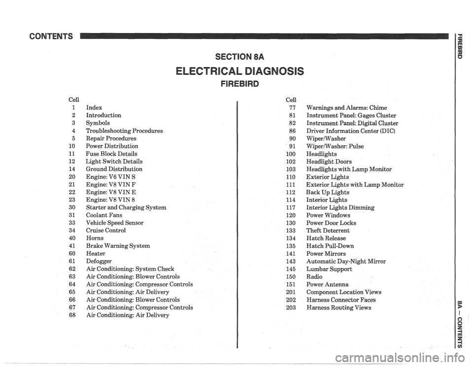
CONTENTS
ELECTRICAL DIAGNOSIS
Cell
1
2
3
4 5
10
11
12 14
20
21
22
23
30
31
33
34
40
4
1
60
61
62
63
64
65
66
67
68
Index
Introduction
Symbols
Troubleshooting Procedures Repair Procedures
Power Distribution
Fuse Block Details
Light Switch Details
Ground Distribution
Engine:
V6 VIN S
Engine: V8 VIN
F
Engine: V8 VIN E
Engine:
V8 VIN 8
Starter and Charging System
Coolant Fans
Vehicle Speed Sensor
Cruise Control Horns
Brake Warning System
Heater
Defogger
Air Conditioning: System Check
Air Conditioning: Blower Controls
Air Conditioning: Compressor Controls
Air Conditioning: Air Delivery
Air Conditioning: Blower Controls
Air Conditioning: Compressor Controls
Air Conditioning: Air Delivery Cell
77
8
1
82
86 90
9
1
100
102
103
110
111
112
114
117
120
130
133
134
135
141
143
145
150
151
201 202
203
Warnings and Alarms: Chime
Instrument Panel: Gages Cluster
Instrument Panel:
Digital Cluster
Driver Information Center
(DIC)
WiperlWasher
WiperlWasher: Pulse
Headlights
Headlight Doors
Headlights with Lamp Monitor
Exterior Lights
Exterior Lights with Lamp Monitor
Back Up Lights
Interior Lights
Interior Lights Dimming
Power Windows
Power Door Locks
Theft Deterrent
Hatch Release
Hatch Pull-Down
Power Mirrors
Automatic Day-Night Mirror
Lumbar Support
Radio Power Antenna
Component Location Views
Harness Connector Faces
Harness Routing Views
Page 1167 of 1825
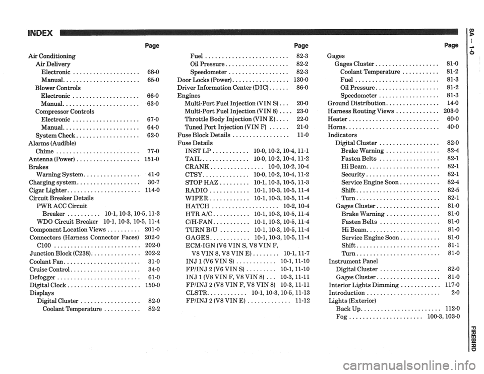
Page
Air Conditioning
Air Delivery
Electronic
.................... 68-0
Manual
....................... 65-0
Blower Controls
Electronic
.................... 66-0
Manual
....................... 63-0
Compressor Controls Electronic
.................... 67-0
Manual
....................... 64-0
................... System Check 62-0
Alarms (Audible)
Chime
......................... 77-0
Antenna(Power) ................... 151-0
Brakes
................. Warning System 41-0
................... Charging system 30-7
...................... Cigar Lighter 114-0
Circuit Breaker Details
PWR ACC Circuit
.......... Breaker 10.1.10.3.10.5.1 1.3
WDO Circuit Breaker
10.1. 10.3. 10.5. 11-4
.......... Component Location Views 201-0
Connectors (Harness Connector Faces) 202-0
el00 .......................... 202-0
............... Junction Block ((2238) 202-2
Coolant Fan
....................... 31-0
Cruise Control
..................... 34-0
Defogger
......................... 61-0
Digital Clock
...................... 150-0
Displays Digital Cluster
.................. 82-0
Coolant Temperature
........... 82-2
Page
......................... Fuel 82-3
................... Oil Pressure 82-2
.................. Speedometer 82-3
................. Door Locks (Power) 130-0
...... Driver Information Center (DIC) 86-0
Engines
... Multi-Port Fuel Injection (VIN S) 20-0
.... Multi-Port Fuel Injection (VIN 8) 23-0
.... Throttle
Body Injection (VIN E) 22-0
...... Tuned
Port Injection (VIN F) 21-0
................. Fuse Block Details 11-0
Fuse Details
........... INST LP 10.0.10.2.10.4.1 1.1
.............. TAIL 10.0.10.2.10.4.1 1.2
................ CRANK 10.0.10.2.1 0.4
.............. CTSY 10~0.10.2.10.4.1 1.2
......... STOP HAZ 10.1.10.3.10.5.1 1.3
............ RADIO 10.1.10.3.10.5.1 1.4
............ WIPER 10.1.10.3.10.5.1 1.4
.................... HATCH 10.2.1 0.4
........... HTR AlC 10.1.10.3.10.5.1 1.4
........... CIH.FAN 10.1.10.3.10.5.1 1.4
......... TURN BIU 10.1.10.3.10.5.1 1.4
............ GAGES 10.1.10.3.10.5.1 1.4
ECM-IGN
(V6 VIN S. V8 VIN F.
........ V8 VIN 8. V8 VIN E) 10.1.1 1.7
............ INJ 1 (V6 VIN S) 10.1.1 1.10
......... FPIINJ 2 (V6 VIN S) 10.1.1 1.10
... INJ 1 (V8 VIN F. V8 VIN 8) 10.3.1 1.11
FPIINJ 2 (V8 VIN F. V8 VIN 8) 10.3.1 1.11
............ CLSTR 10.1.10.3.10.5.1 1.13
............. FPIINJ 2 (V8 VIN E) 11-12
Page
Gages
................... Gages Cluster 81-0
........... Coolant Temperature 81-2
......................... Fuel 81-3
................... Oil Pressure 81-2
.................. Speedometer 81-3
................ Ground Distribution 14-0
Harness Routing Views
............. 203-0
........................... Heater 60-0
............................ Horns 40-0
Indicators
.................. Digital Cluster 82-0
................ Brake Warning 82-4
.................. Fasten Belts 82-1
...................... Hi Beam 82-1
...................... Security 82-1
............ Service Engine Soon 82-4
......................... Shift 82-5
......................... Turn 82-1
................... Gages Cluster 81-0
................ Brake Warning 81-0
.................. Fasten Belts 81-0
...................... Hi Beam 81-0
............ Service Engine Soon 81-0
......................... Shift 81-1
......................... Turn 81-0
Instrument Panel
Digital Cluster
.................. 82-0
Gages Cluster
................... 81-0
............ Interior Lights Dimming 117-0
...................... Introduction 2-0
Lights (Exterior)
........................ Back Up 112-0
...................... Fog 100.3,10 3.0