1988 PONTIAC FIERO check engine light
[x] Cancel search: check engine lightPage 1325 of 1825
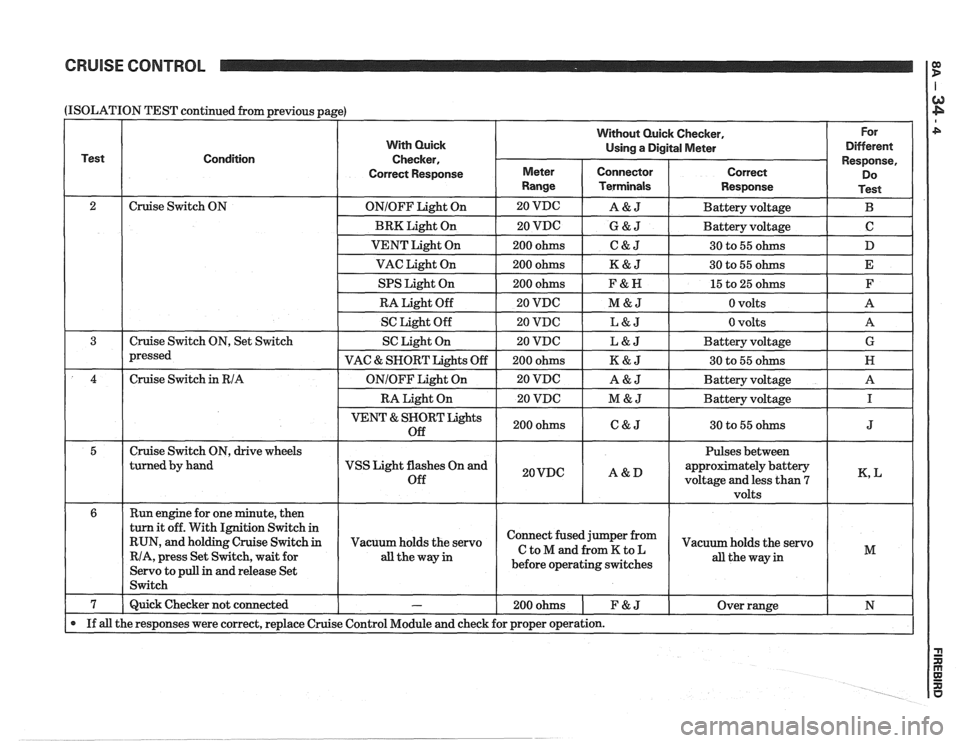
CRUISE CONTROL
(ISOLATION
Test
2 3
4
5
6
7
If all
TEST continued from previous page)
Condition
Cruise Switch ON
Cruise Switch ON, Set Switch
pressed
Cruise Switch
in RIA
Cruise Switch ON, drive wheels
turned by hand
Run engine for one minute, then
turn it off. With Ignition Switch in
RUN, and holding Cruise Switch
in
RIA, press Set Switch, wait for
Servo to pull
in and release Set
Switch
Quick Checker not connected
the responses were correct, replace Cruise
With Quick
Checker,
Correct Response
ONIOFF Light On
BRK Light On
VENT Light On
VAC Light On
SPS Light On
RA Light Off
SC Light Off
SC Light On
VAC
& SNORT Lights Off
ONIOFF Light On
RA Light On
VENT & SNORT Lights
Off
VSS Light flashes On and
Off
Vacuum holds the servo
all theway in
-
Control Module and check
Without Quick Checker, For
Using
a Digital Meter Different
Meter
Range
20 VDG
20 VDC
200 ohms
200 ohms
200 ohms
20 VDC
20 VDC
20 VDC
200 ohms
20 VDC
20 VDC
200 ohms
20VDC
Connector Terminals
A&J
G&J
C&J
K&J
F&N
M&J
L&J
L&J
K&J
A&J
M&J
C&J
A&D
Response,
Correct Do
Response Test
Battery voltage B
Battery voltage C
30 to 55 ohms D
30 to 55 ohms E
15 to 25 ohms F
0 volts A
0 volts
A
Battery voltage G
30 to 55 ohms N
Battery voltage A
Battery voltage
I
30 to 55 ohms J
Pulses between
approximately battery
voltage and less than
7 K, L
volts
Connect fused jumper from
CtoMandfromKtoL
before operating switches
200ohms 1 F&J
for proper operation.
Vacuum holds the servo
all the way in M
Over range N
Page 1334 of 1825
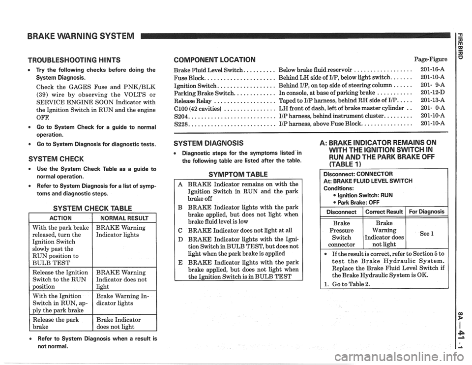
BRAKE VVARNlNG SYSTEM
TROUBLESHOOTING HINTS
0 Try the following checks before doing the
System Diagnosis.
Check the GAGES Fuse and PNKIBLK
(39) wire by observing the VOLTS or
SERVICE ENGINE SOON Indicator with
the Ignition Switch in RUN and the engine
OFF.
0 Go to System Check for a guide to normal
operation.
0 Go to System Diagnosis for diagnostic tests.
SYSTEM CHECK
Use the System Check Table as a guide to
normal operation.
e Refer to System Diagnosis for a list of symp-
toms and diagnostic steps.
SYSTEM CHECK TABLE
RUN position to
BULB TEST
COMPONENT LOCATION Page-Figure
.................. Brake Fluid Level Switch. ......... Below brake fluid reservoir 201-16-A
..................... Fuse Block. Behind
LH side of IIP, below light switch. ...... 201-10-A
................. Ignition Switch. Behind IIP, on
top side of steering column ...... 201- 9-A
Parking Brake Switch.
............ In console, at base of parking brake ........... 201-12-D
................... Release Relay Taped
to IIP harness, behind RH side of IIP. .... 201-13-A
................ (2100 (42 cavities) LR
front of dash, left of brake master cylinder .. 201- 0-A
........................... S204. IIP harness, behind instrument cluster. ........ 201-10-A
.......................... ............... S228. IIP harness, above Fuse Block. 201-10-A
SYSTEM DIAGNOSIS
0 Diagnostic steps for the symptorns listed'in
the following table are listed after the table.
A: BRAKE INDICATOR REMAINS ON
WITH THE
IGNITION SWITCH IN
RUN AND THE PARK BRAKE OFF
(TABLE
1)
SYMPTOM TABLE
A BRAKE Indicator remains on with the
Ignition Switch
in RUN and the park
brake off
B BRAKE Indicator lights with the park
brake applied, but does not light when
brake fluid level is low
C BRAKE Indicator does not light at all
D BRAKE Indicator lights with the Igni-
tion Switch in BULB TEST, but does not
light when the park brake is applied
E BRAKE Indicator lights with the park
brake applied, but does not light when
the Ignition Switch is in BULB TEST
Refer to System Diagnosis when a result is
not normal. Disconnect:
CONNECTOR
At: BRAKE FLUID LEVEL SWITCH
Conditions:
0 Ignition Switch: RUN
0 Park Brake: OFF
Pressure Warning
If the result is correct, refer to Section
5 to
test the Brake Hydraulic System.
Replace the Brake Fluid Level Switch if
the Brake Hydraulic System is OK.
1. Go to Table2.
Page 1351 of 1825
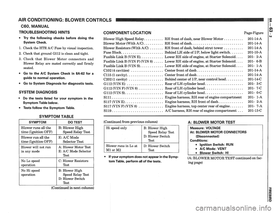
AIR CONDITIONING: BLOWER CONTROLS
C60, MANUAL
TROUBLESHOOTING
HINTS
Try the following checks before doing the
System Check.
1. Check the HTR A/C Fuse by visual inspection.
2. Check that ground
6112 is clean and tight.
3. Check that Blower Motor connectors and
Blower Relay are mated correctly and firmly
seated.
Go to the A/C System Check in 8A-62 for a
guide to normal operation.
Q Go to System Diagnosis for diagnostic tests.
SYSTEM DIAGNOSIS
Do the tests listed for your symptom in the
Symptom Table below.
Q Tests follow the Symptom Table.
SYMPTOM TABLE
SYMPTOM
Blower runs all the
time (Ignition OFF)
Blower run
all the
time (Ignition OFF)
Blower will not run
in any mode
No Lo speed
operation
COMPONENT LOCATION Page-Figure
Blower High Speed Relay.
......... RH front of dash, near Blower Motor ..........
Blower Motor (With Ale) .......... RH front of dash. ..........................
Blower Resistors (With AIC) ....... RH front of dash, behind strut tower ..........
Fuse Block. ..................... Behind LH side of IIP, below light switch. ......
Fusible Link B (VIN E). ........... Lower RH side of engine, at Starter Solenoid. ...
Fusible Link B (VIN F) (VIN 8) ..... Lower RH side of engine, at Starter Solenoid. ...
Fusible Link B (VIN S). ........... Lower RH side of engine, at Starter Solenoid. ...
(2102 (4 cavities) ................. Center front of dash. .......................
6115 (1 cavity). .................. Center front of dash. .......................
(2202 (1 cavity) .................. Behind. center of IIP, near control head. ........
6112 (VIN E) ................... Rear of LN cylinder head. ...................
6112 (VIN F) (VIN 8) ............. Rear of LH cylinder head. ...................
6112 (VIN S). ................... Rear of LH cylinder head. ...................
Slll ........................... Engine harness, RH rear of engine compartment
S117 (VINE)
.................... Engine harness, RH front of dash. ............
S117 (VIN F) (VIN 8) ............. Engine harness, top center rear of engine. ......
S119. .......................... AIC harness, RH rear of engine compartment ...
DO TEST
B : Blower High
Speed Relay Test
E:
AIC Mode
Selector Test
A: Blower Motor Test
E: A!C Mode Selector
Test
C: Blower Resistors
Test (Continued
from previous column)
A: BLWER MOTOR TEST
Measure: VOLTAGE
At: BLOWER MOTOR CONNECTORS
(Disconnected)
Conditions:
Ignition Switch: RUN
Q NC Mode: VENT
Blower Switch:
HI
If your symptom does not appear in the SY~P- (A: BLOWER MOTOR TEST continued on fat- tom Table, perform all of the tests. ing page)
Hi speed only
Blower runs in Lo at
M1 or M2
No Hi speed
operation
B: Blower High
Speed Relay Test
D: Blower Switch
Test
D: Blower Switch
Test
B: Blower High
Speed Relay Test
D: Blower Switch
I Test 1
(Continued in next column)
Page 1358 of 1825
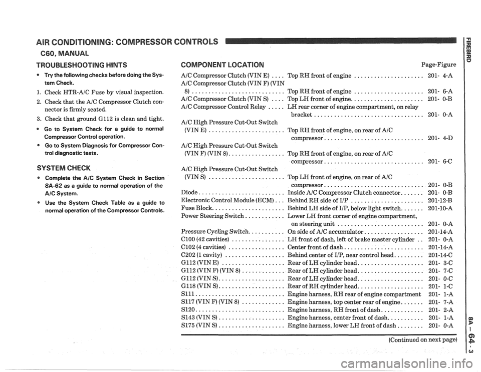
AIR CONDITIONING: COMPRESSOR CONTROLS
660. MANUAL
TROUBLESHOOTING
HINTS
Try the following checks before doing the Sys-
tem Check
.
1 . Check HTR-A/C Fuse by visual inspection .
2 . Check that the A/C Compressor Clutch con-
nector is firmly seated
.
3 . Check that ground 6112 is clean and tight .
Go to System Check for a guide to normal
Cornpressor Control operation
.
Go to System Diagnosis for Compressor Con-
trol diagnostic tests
.
SYSTEM CHECK
Complete the AIC System Check in Section
8A-62 as a guide to normal operation of the
AIC Systern .
Use the System Check Table as a guide to
normal operation of the Compressor Controls
.
COMPONENT LOCPaTlON Page-Figure
.... ..................... AIC Compressor Clutch (VIN E)
Top RH front of engine 201-
4-A
Ale Compressor Clutch (VIN F) (VIN
..................... ............................ 8) Top RH front of engine 201- 6-A
.... ...................... AlC Compressor Clutch (VIN S)
Top LH front of engine 201- 0-B
..... AIC Compressor Control Relay
LH rear corner of engine compartment. on relay
................................. bracket 201- 0-A
A/C High Pressure Cut-Out Switch
....................... (VIN E)
Top RH front of engine. on rear of AIC
.............................. compressor 201- 4-D
Ale Nigh Pressure Cut-Out Switch
................. (VIN F) (VIN 8) Top RN front of engine. on rear of AIC
.............................. compressor 201- 6-C
AIC High Pressure Cut-Out Switch
....................... (VIN S)
Top LH front of engine. on rear of AIC
.............................. compressor 201- 0-B
Diode
.......................... Inside AIC Compressor Clutch connector ....... 201- 0-B
Electronic Control Module (ECM)
... Behind RH side of I/P ...................... 201-12-B
Fuse Block
...................... Behind LH side of IIP. below light switch ....... 201-10-A
............ Power Steering Switch
Lower LR front corner of engine compartment.
.......................... on steering unit 201- 0-A
.................. Pressure Cycling Switch ........... On side of AlC accumulator 201-14-A
.. el00 (42 cavities) ................ LH front of dash. left of brake master cylinder
201- 0-A
........................ 6102 (4 cavities) ................. Center front of dash 201-14-A
......... C202 (1 cavity) .................. Behind center of IIP. near control head
201-14-C
6112 (VINE)
................... Rear of LH cylinder head .................... 201- 3-C
6112 (VIN F) (VIN 8)
............. Rear of LH cylinder head .................... 201- 7-C
G112 (VIN
S) .................... Rear of LH cylinder head .................... 201- 0-C
6118 (VIN S) .................... Rear of RH cylinder head .................... 201- 1-C
S111 ........................... Engine harness. RN rear of engine compartment 201- 1-A
S117 (VIN
F) (VIN 8) ............. Engine harness. top center rear of engine ....... 201- 7-A
S120
........................... Engine harness. RH front ofdash ............. 201- 2-A
........... S143 (VIN S) .................... Engine harness. center front of dash
201- 1-A
S175 (VIN S) .................... Engine harness. lower LH front of dash ........ 201- 0-A
(Continued on next page)
Page 1371 of 1825
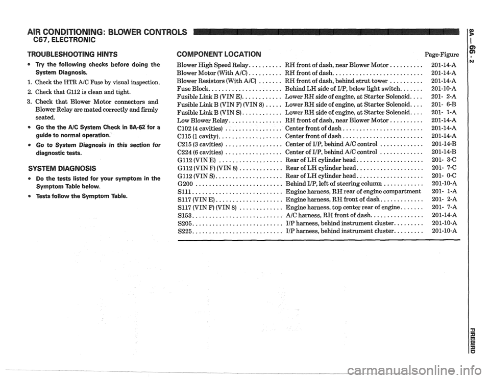
AIR CONDITIONING: BLOWER CONTROLS
TROUBLESHOOTING NlNTS
a Try the following checks before doing the
System Diagnosis
.
1 . Check the HTR A/C Fuse by visual inspection .
2 . Check that 6112 is clean and tight .
3 . Check that Blower Motor connectors and
Blower Relay are mated correctly and firmly
seated
.
a Go the the AIC Systern Check in 813-62 for a
guide to normal operation
.
Go to Systern Diagnosis in this section for
diagnostic tests
.
SYSTEM DIAGNOSIS
Do the tests listed for your symptom in the
Symptom Table below
.
Tests follow the Symptom Table .
COMPONENT LOCATION Page-Figure
Blower High Speed Relay
.......... RH front of dash. near Blower Motor ..........
Blower Motor (With AIC) .......... RH front of dash ...........................
Blower Resistors (With AIC) ....... RH front of dash. behind strut tower ..........
...................... Fuse Block
Behind LH side of IIP. below light switch .......
............ Fusible Link B (VIN E) Lower RH side of engine. at Starter Solenoid ....
Fusible Link B (VIN F) (VIN 8) ..... Lower RH side of engine. at Starter Solenoid ....
............ Fusible Link B (VIN S) Lower RN side of engine. at Starter Solenoid ....
................ Low Blower Relay RH front of dash. near Blower Motor ..........
........................ ................. C102 (4 cavities) Center
front of dash
................... ........................ C115 (1 cavity) Center
front of dash
................. ............. C215 (3 cavities) Center
of IIP. behind AlC control
................. ............. 6224 (6 cavities) Center
of IIP. behind Ale control
................... .................... 6112 (VIN E) Rear of LH cylinder head
............. .................... 6112 (VIN F) (VIN 8) Rear of LH cylinder head
.................... .................... 6112 (VIN S) Rear
of LN cylinder head
.......................... ............ 6200 Behind I/P. left of steering column
........................... Slll Engine harness. RN rear of engine compartment
.................... ............. S117 (VIN E) Engine harness. RH front of dash
............. ....... S117 (VIN F) (VIN 8) Engine harness. top center rear of engine
........................... ................ S153 AIC harness. RH front of dash
........................... ......... S205 IIP harness. behind instrument cluster
........................... S225 IIP harness. behind instrument cluster .........
Page 1380 of 1825
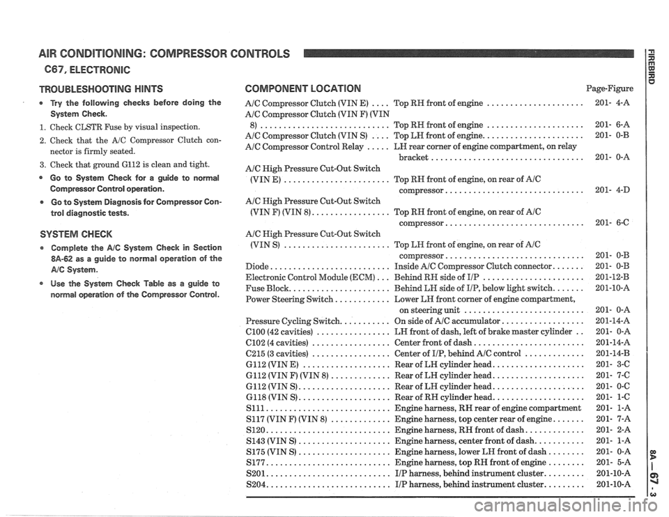
AIR CONDITIONING: COMPRESSOR CONTROLS
C67. ELECTRONIC
TROUBLESHOOTING HINTS
Try the following checks before doing the
System Check
.
1 . Check CLSTR Fuse by visual inspection .
2 . Check that the A/C Compressor Clutch con-
nector is firmly seated
.
3 . Check that ground 6112 is clean and tight .
Go to System Check for a guide to normal
Compressor Control operation
.
o Go to System Diagnosis for Compressor Con-
trol diagnostic tests
.
SYSTEM CHECK
Complete the AIC System Check in Section
$A-62 as a guide to normal operation of the
AIC System .
Use the sy&esla Check Table as a guide to
normal operation
of the Compressor Control .
COMPONENT LOCATION Page-Figure
.... ..................... A/C Compressor Clutch (VIN E) Top
RH front of engine 201-
4-A
AIC Compressor Clutch (VIN F) (VIN
..................... ............................ 8) Top RN front of engine 201- 6-A
.... ...................... A/C Compressor Clutch (VIN S) Top LH front of engine 201-
0-B
A/C Compressor Control Relay ..... LN rear comer of engine compartment. on relay
................................. bracket 201- 0-A
Ale High Pressure Cut-Out Switch
(VIN E)
....................... Top RH front of engine. on rear of AIC
.............................. compressor 201- 4-D
AIC High Pressure Cut-Out Switch
(VIN F) (VIN 8)
................. Top RN front of engine. on rear of AlC
.............................. compressor 201- 6-C
A/C Nigh Pressure Cut-Out Switch
(VIN S)
....................... Top LH front of engine. on rear of AIC
.............................. coqressor 201- 0-B
Diode
.......................... Inside AIC Compressor Clutch connector ....... 201- 0-B
Electronic Control Module
(ECM) ... Behind RH side of I/P ...................... 201-12-B
Fuse Block
...................... Behind LH side of IIP. below light switch ....... 201-10-A
Power Steering Switch
............ Lower LH front comer of engine compartment.
.......................... on steering unit 201- 0-A
Pressure Cycling Switch
........... On side of Ale accumulator .................. 201-14-A
ClOO (42 cavities) ................ LN front of dash. left of brake master cylinder .. 201- 0-A
6102 (4 cavities) ................. Center front of dash ........................ 201-14-A
6215 (3 cavities) ................. Center of I/P. behind AlC control ............. 201-14-B
6112 (VIN E)
................... Rear of LH cylinder head .................... 201- 3-C
6112 (VIN F) (VIN 8)
............. Rear of LH cylinder head .................... 201- 7-6
6112 (VIN S) .................... Rear of LH cylinder head .................... 201- 0-C
6118 (VIN S)
.................... Rear of RH cylinder head .................... 201- 1-6
S111 ........................... Engine harness. RH rear of engine compartment 201-
1-A
S117 (VIN
F) (VIN 8) ............. Engine harness. top center rear of engine ....... 201- 7-A
S120
........................... Engine harness. RIP front of dash ............. 201- 2-A
S143 (VIN S)
.................... Engine harness. center front of dash ........... 201- 1-A
S175 (VIN S)
.................... Engine harness. lower LH front of dash ........ 201- 0-A
S177
........................... Engine harness. top RH front of engine ........ 201- 5-A
S201
........................... IIP harness. behind instrument cluster ......... 201-10-A
S204
........................... I/P harness. behind instrument cluster ......... 201-10-A
Page 1389 of 1825
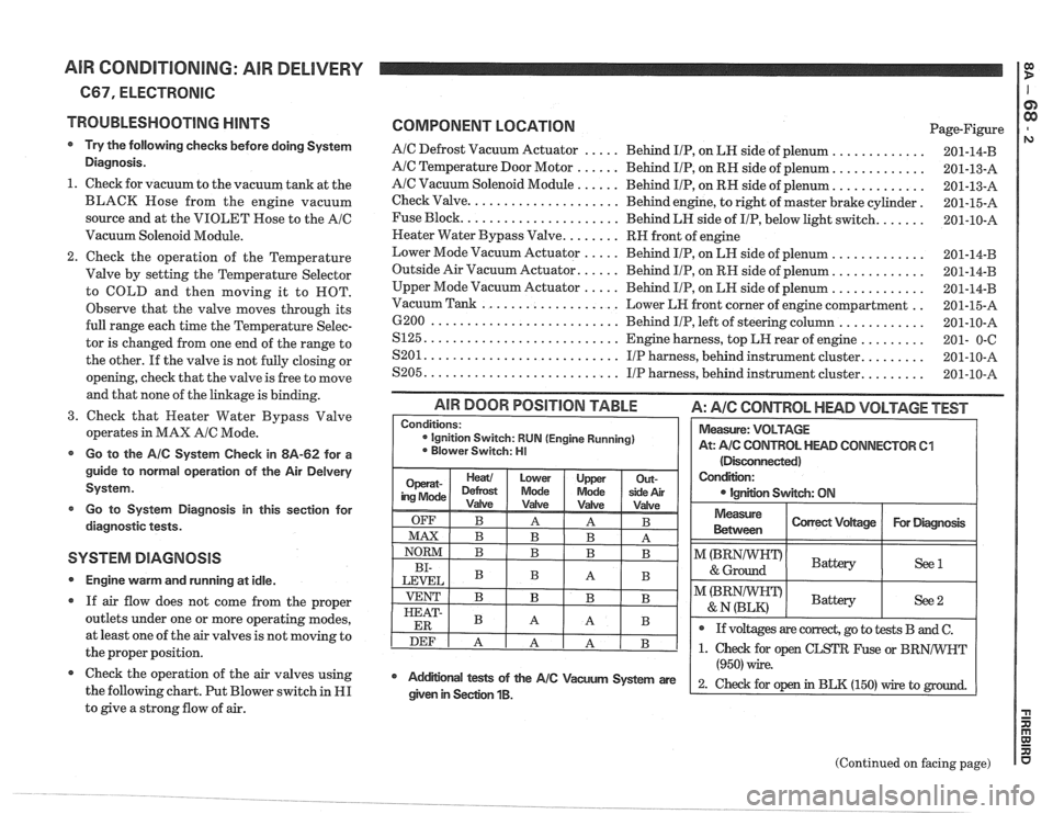
AIR CONDITIONING: AIR DELIVERY I g
667, ELECTRONIC
TROUBLESHOOTING
HINTS
Try the following checks before doing System
Diagnosis.
1. Check for vacuum to the vacuum tank at the
BLACK Hose from the engine vacuum
source and at the VIOLET Rose to the
AIC
Vacuum Solenoid Module.
Check the operation of the Temperature
Valve by setting the Temperature Selector
to COLD and then moving it to ROT.
Observe that the valve moves through its
full range each time the Temperature Selec-
tor is changed from one end of the range to
the other. If the valve is not fully closing or
opening, check that the valve is free to move
and that none of the linkage is binding.
3. Check that Heater Water Bypass Valve
operates in MAX
AIC Mode.
Go to the AIC System Check in 8A-62 for a
guide to normal operation of the Air
Delvery
System.
Go to System Diagnosis
in this section for
diagnostic tests.
SYSTEM DIAGNOSIS
Engine warm and running at idle.
If air flow does not come from the proper
outlets under one or more operating modes,
at least one of the air valves is not moving to
the proper position.
@ Check the operation of the air valves using
the following chart. Put Blower switch in
HI
to give a strong flow of air.
COMPONENT LOCATION Page-Figure
AIC Defrost Vacuum Actuator ..... Behind IIP, on LH side of plenum .............
AIC Temperature Door Motor ...... Behind IIP, on RH side of plenum. ............
AIC Vacuum Solenoid Module ...... Behind IIP, on RH side of plenum. ............
Check Valve. .................... Behind engine, to right of master brake cylinder.
Fuse Block.
..................... Behind LH side of IIP, below light switch. ......
Neater Water Bypass Valve. ....... RH front of engine
Lower Mode Vacuum Actuator
..... Behind IIP, on LH side of plenum .............
Outside Air Vacuum Actuator. ..... Behind IIP, on RH side of plenum. ............
Upper Mode Vacuum Actuator ..... Behind IIP, on LH side of plenum .............
.. Vacuum Tank ................... Lower LH front corner of engine compartment
6200
.......................... Behind IIP, left of steering column ............
S125. .......................... Engine harness, top LH rear of engine .........
........ S201. .......................... IIP harness, behind instrument cluster.
........ S205. .......................... IIP harness, behind instrument cluster.
(Disconnected)
Condition:
IgnEon Swgch: ON
AIR DOOR POSITION TABLE A: AIC CONTROL HEAD VOLTAGE TEST
Measure
Between I Correct Vdtage / For Diagmsk I
Conditions: ignition Switch: RUN (Engine Running)
Blower Switch: HI
I"(BRNIWIFDI & Ground Battery ( See1 I
Measure: VOLTAGE
At:
A/C CONTROL HEAD CONNECTOR 61
I I
@ If voltages are correct, go to tests B and C.
(Continued on facing page)
Mdifional tests of the AIC Vacum System are
(950) wire.
2- ~hd for op in BLK (150) rrire to given in Seclion 1B.
Page 1404 of 1825
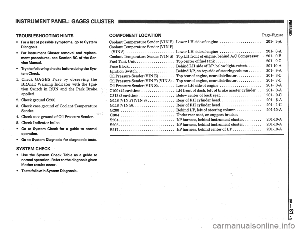
INSTRUMENT PANEL: GAGES CLUSTER
TROUBLESHOOTING HINTS COMPONENT LOCATION Page-Figure
* For a list of possible symptoms, go to System Coolant Temperature Sender (VIN E) Lower LH side of engine ....................
Diangosis. Coolant Temperature Sender (VIN F)
....................... .................... * For Instrument Cluster removal and replace- (VIN 8). Lower
LH side of engine
ment procedures, see Section 8C of the Ser- Coolant Temperature Sender (VIN S) Top LN front of engine, behind A/C Compressor.
.................. ..................... vice Manual. Fuel Tank Unit Top center of fuel tank.
..................... ...... * Try the following checks before doing the Sys- Fuse Block. Behind
LH side of IIP, below light switch.
................. tem Check. Ignition Switch. Behind IIP, on
top side of steering co
....... ........... Oil Pressure Sender (VIN E) Top rear of engine, near distributor. 1. Check GAGES Fuse by observing the . ........... Oil Pressure Sender (VIN F) (VIN 8) Top
rear of engine, near distributor.
BRAKE Warning Indicator with the Igni- Oil Pressure Sender (VIN S) ........ Lower LN side of engine .................... tion Switch in RUN and the Park Brake ................ .. el00 (42 cavities) LN
front of dash, left of brake master cylinder
applied.
................. C313 (3 cavities) Below
center of back seat. ...................
2. Check ground 6200. . 6118 (VIN F) (VIN 8) ............. Rear of RN cylinder head. ...................
.................... ................... 3. Check case ground of Coolant Temperature 6118
(VIN S) Rear
of RH cylinder head.
.......................... ............ Sender. 6200 Behind I/P, left of steering column ' h .......................... 4. Check case ground of Oil Pressure Sender. 6304 Under rear seat,
on support bracket
.......................... S204. IIP harness, behind instrument cluster. ........ 5. Check Indicator bulbs. .......................... ........ S205. I/P harness, behind instrument cluster. * Go to System Check for a guide to normal .......................... S217. I/P harness, behind center of IIP .............. operation.
* Go to Systern Diagnosis for diagnostic tests.
SYSTEM CHECK
* Use the System Check Table as a guide to
normal operation. Refer to the diagnosis given
if other results occur.
* Tests follow in System Diagnosis.