1987 SUZUKI GRAND VITARA clock
[x] Cancel search: clockPage 213 of 962
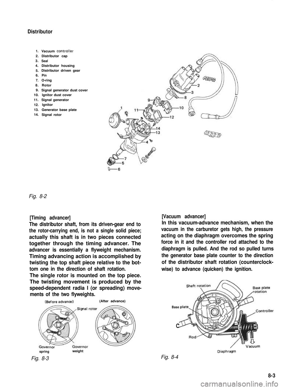
Distributor
1.Vacuum ControlJer2.Distributor cap
3.
Seal4. Distributor housing
5. Distributor driven gear
6.
Pin
7.
O-ring
8. Rotor
9. Signal generator dust cover
10. lgnitor dust cover
11. Signal generator
12. lgnitor
13. Generator base plate
14. Signal rotor
Fig. 8-2
[Timing advancer] [Vacuum advancer]
The distributor shaft, from its driven-gear end to
the rotor-carrying end, is not a single solid piece;
actually this shaft is in two pieces connected
together through the timing advancer. The
advancer is essentially a flyweight mechanism.
Timing advancing action is accomplished by
twisting the top shaft piece relative to the bot-
tom one in the direction of shaft rotation.
The single rotor is mounted on the top piece.
The twisting movement is produced by the
speed-dependent radia I (or spreading) move-
ments of the two flyweights.
In this vacuum-advance mechanism, when the
vacuum in the carburetor gets high, the pressure
acting on the diaphragm overcomes the spring
force in it and the controller rod attached to the
diaphragm is pulled. And the rod so pulled turns
the generator base plate counter to the direction
of the distributor shaft rotation (counterclock-
wise) to advance (quicken) the ignition. (Before
advanca)
(After advance)
Base
C
/ -Vacuum DiaphragTI
spring
Fig. 8-3
weight
Fig. 8-4
8-3
Page 219 of 962
Ignition Timing
Ignition timing10” BTDC at
800 * 50 r/min
1 Ignition orderIl-3-4-2I
When checking and adjusting ignition timing,
be sure to use timing light (09900-27301 or
09900-27311).
NOTE:
Prior to check and adjustment of ignition timing,
make sure that head lights, heater fan, rear
defogger (if equipped), and air conditioner (if
equipped) are “OFF”. If any one of these
systems is “ON”,idle up system operates and
engine idle speed will be out of the specification.
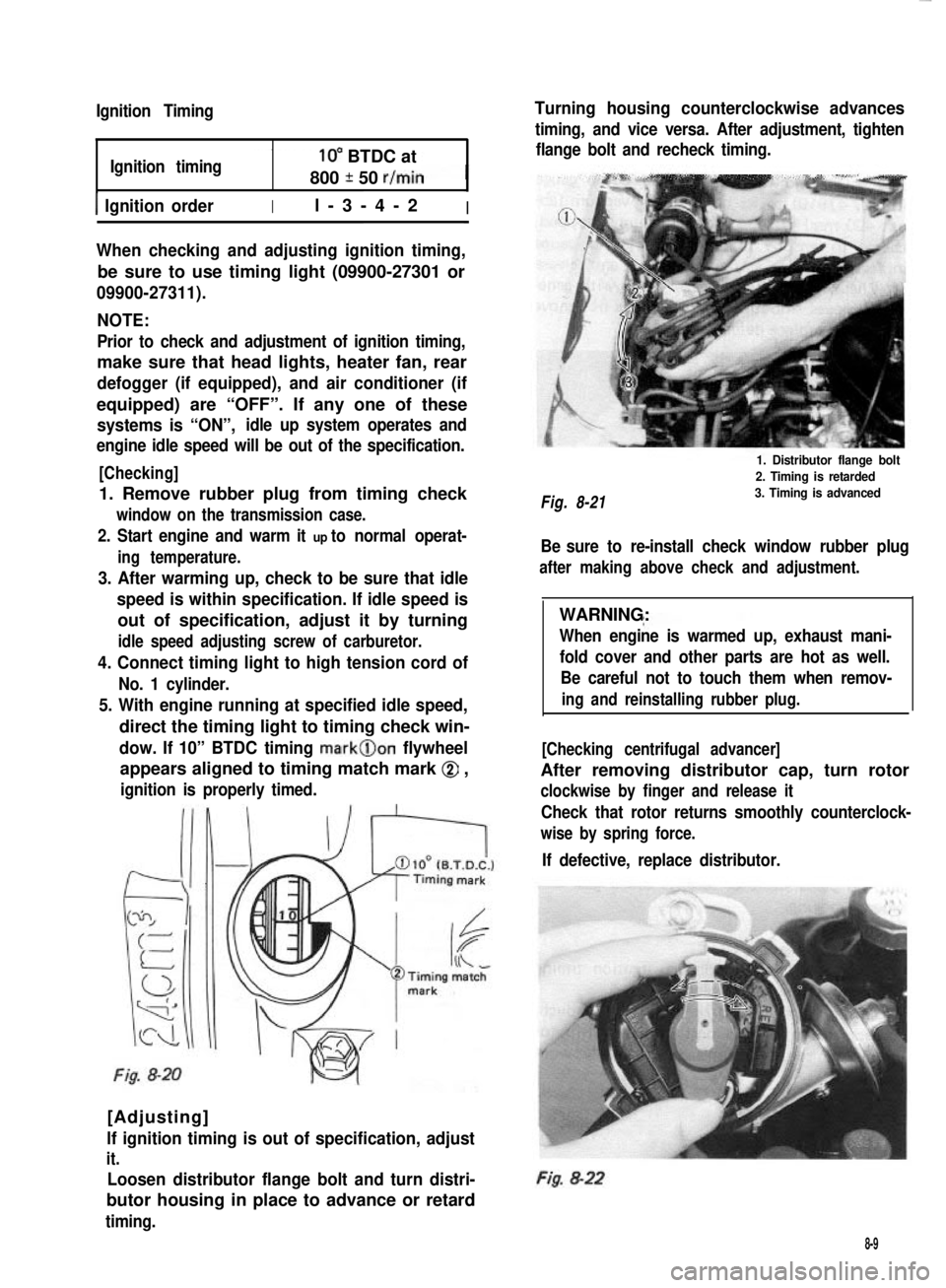
[Checking]
1. Remove rubber plug from timing check
window on the transmission case.
2. Start engine and warm it up to normal operat-
ing temperature.
3. After warming up, check to be sure that idle
speed is within specification. If idle speed is
out of specification, adjust it by turning
idle speed adjusting screw of carburetor.
4. Connect timing light to high tension cord of
No. 1 cylinder.
5. With engine running at specified idle speed,
direct the timing light to timing check win-
dow. If 10” BTDC timing mark@on flywheel
appears aligned to timing match mark @ ,
ignition is properly timed.
Fig. 8-20
[Adjusting]
lf ignition timing is out of specification, adjust
it.
Loosen distributor flange bolt and turn distri-
butor housing in place to advance or retard
timing.
Turning housing counterclockwise advances
timing, and vice versa. After adjustment, tighten
flange bolt and recheck timing.
Fig. 8-21
1. Distributor flange bolt
2. Timing is retarded
3. Timing is advanced
Be sure to re-install check window rubber plug
after making above check and adjustment.
WARNING:
When engine is warmed up, exhaust mani-
fold cover and other parts are hot as well.
Be careful not to touch them when remov-
ing and reinstalling rubber plug.
[Checking centrifugal advancer]
After removing distributor cap, turn rotor
clockwise by finger and release it
Check that rotor returns smoothly counterclock-
wise by spring force.
If defective, replace distributor.
Fig. 8-22
8-9
Page 221 of 962
8-3. IMPORTANT REMINDERS FOR
INSTALLATIONDistributor
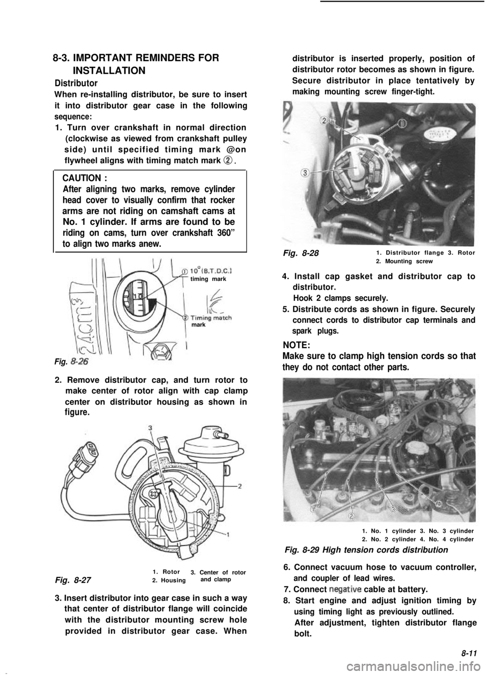
When re-installing distributor, be sure to insertit into distributor gear case in the following
sequence:
1. Turn over crankshaft in normal direction (clockwise as viewed from crankshaft pulley
side) until specified timing mark @on flywheel aligns with timing match mark
0.
CAUTION :
After aligning two marks, remove cylinder
head cover to visually confirm that rocker
arms are not riding on camshaft cams at
No. 1 cylinder. If arms are found to be
riding on cams, turn over crankshaft 360”
to align two marks anew.
lO’(B.T.D.C.1timing mark
mark
Fig.
2. Remove distributor cap, and turn rotor to make center of rotor align with cap clamp
center on distributor housing as shown in
figure.
1. Rotor
Fig. 8-27 3. Center of rotor
2. Housing and clamp
3. Insert distributor into gear case in such a way that center of distributor flange will coincide
with the distributor mounting screw holeprovided in distributor gear case. When distributor is inserted properly, position of
distributor rotor becomes as shown in figure.
Secure distributor in place tentatively by
making mounting screw finger-tight.
Fig. 8-28 1. Distributor flange 3. Rotor
2. Mounting screw
4. Install cap gasket and distributor cap to
distributor. Hook 2 clamps securely.
5. Distribute cords as shown in figure. Securely
connect cords to distributor cap terminals and
spark plugs.
NOTE:
Make sure to clamp high tension cords so that
they do not contact other parts.
1. No. 1 cylinder 3. No. 3 cylinder
2. No. 2 cylinder 4. No. 4 cylinder
Fig. 8-29 High tension cords distribution
6. Connect vacuum hose to vacuum controller,
and coupler of lead wires.
7. Connect negative cable at battery.
8. Start engine and adjust ignition timing by
using timing light as previously outlined.
After adjustment, tighten distributor flange
bolt.
8-11
Page 225 of 962
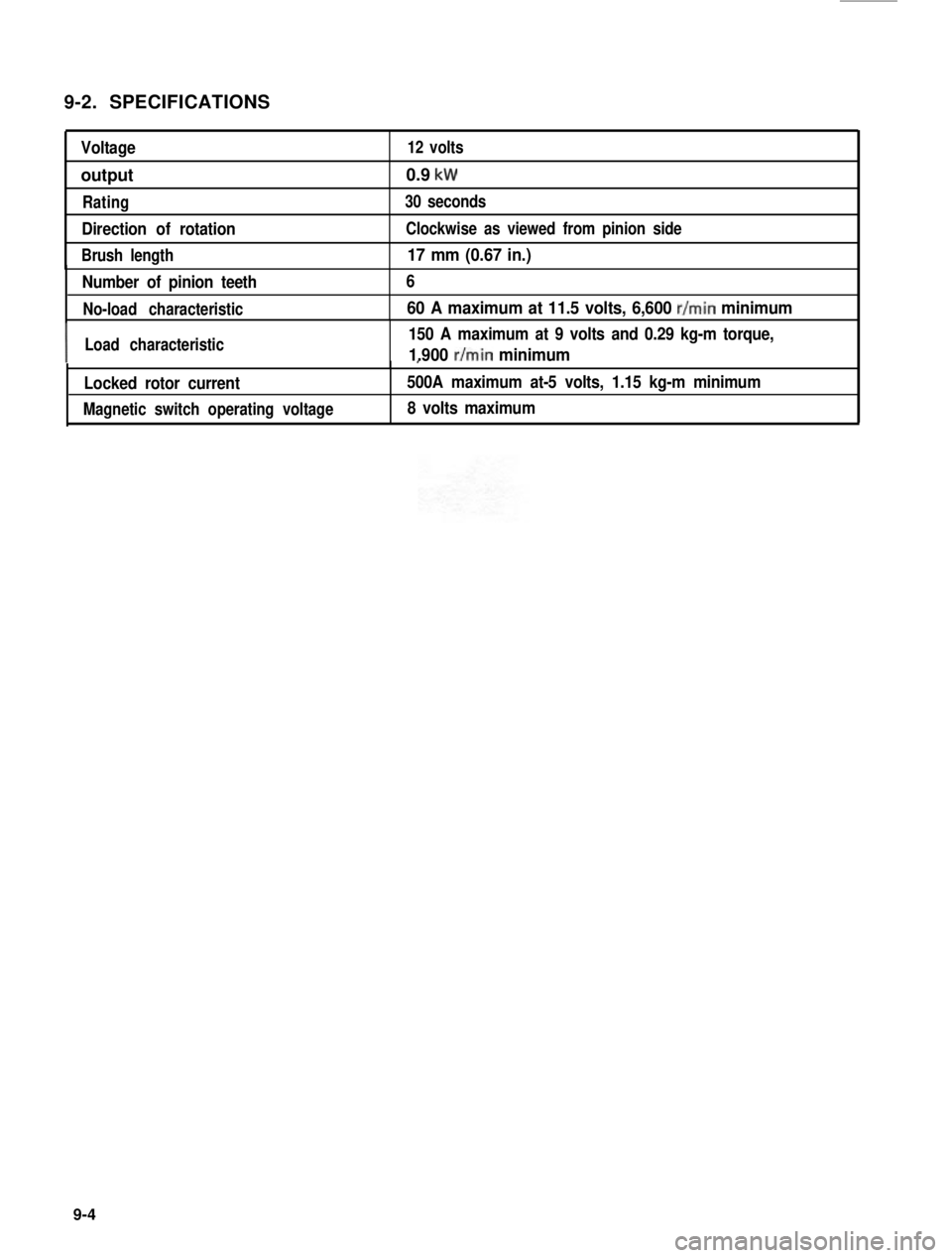
9-2. SPECIFICATIONS
Voltage12 volts
output0.9 kW
Rating30 seconds
Direction of rotationClockwise as viewed from pinion side
Brush length17 mm (0.67 in.)
Number of pinion teeth
No-load characteristic
6
60 A maximum at 11.5 volts, 6,600 r/min minimum
ILoad characteristic150 A maximum at 9 volts and 0.29 kg-m torque,
1.900 r/min minimum,
500A maximum at-5 volts, 1.15 kg-m minimum
8 volts maximum
Locked rotor current
Magnetic switch operating voltage
9-4
Page 236 of 962
The alternator features a solid state regulator
that is mounted inside the alternator. All regula-
tor components are enclosed into a solid mold,
and this unit along with the brush holder assemb-
ly is attached to the slip ring end frame. The
regulator voltage setting cannot be adjusted.
The alternator rotor bearings contain enough
grease to eliminate the need for periodic lubri-
cation. Two brushes carry current through the
two slip rings to the field coil mounted on the
rotor, and under normal conditions will provide
long period of attention-free service.
The stator windings are assembled on the inside
of a laminated core that forms part of the
alternator frame. A rectifier bridge connected
to the stator windings contains six diodes,
and electrically changes the stator A.C. voltages
to a D.C. voltage which appears at the generator
output terminal.
The neutral diodes serve to convert the voltage
fluctuation at the neutral point to direct current
for increasing the alternator output.
A condenser mounted in the end frame protects
the diodes from high voltages and suppresses
radio noise.
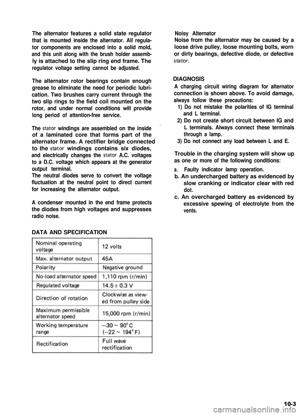
DATA AND SPECIFICATION
Nominal operating
voltaga
Max. alternator output
12 volts
45A
No-load alternator speed
IDirection of rotationClockwise as view-
ed from oullev side
Maximum permissible
alternator speed
Working temperature
range
Rectification
15,000 rpm (r/min)
-3o- 90°C
(-22 - 194” F)
Full wave
rectification
Noisy Alternator
Noise from the alternator may be caused by a
loose drive pulley, loose mounting bolts, worn
or dirty bearings, defective diode, or defective
stator.
DIAGNOSIS
A charging circuit wiring diagram for alternator
connection is shown above. To avoid damage,
always follow these precautions:
1) Do not mistake the polarities of IG terminal
and L terminal.
2) Do not create short circuit between IG and
L terminals. Always connect these terminals
through a lamp.
3) Do not connect any load between L and E.
Trouble in the charging system will show up
as one or more of the following conditions:
a.Faulty indicator lamp operation.
b. An undercharged battery as evidenced by
slow cranking or indicator clear with red
dot.
c. An overcharged battery as evidenced by
excessive spewing of electrolyte from the
vents.
10-3
Page 293 of 962
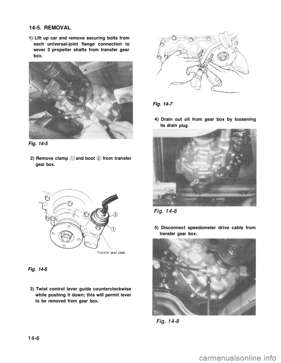
14-5. REMOVAL
1) Lift up car and remove securing bolts from
each universal-joint flange connection to
sever 3 propeller shafts from transfer gear
box.
Fig. 14-5
2) Remove clamp @ and boot @ from transfer
gear box.
Fig. 14-7
4) Drain out oil from gear box by loosening
its drainplug.
Fig. 14-8
5) Disconnect speedometer drive cable from
transfer gear box.
Transfer‘gear case
Fig. 14-6
3) Twist control lever guide counterclockwise
while pushing it down; this will permit lever
to be removed from gear box.
14-6
Fig. 14-8
Fig. 14-9
Page 416 of 962
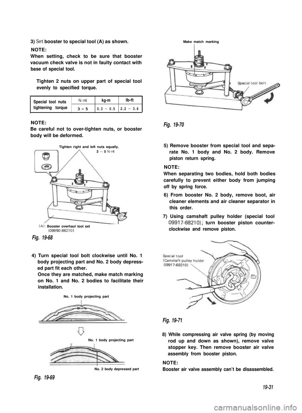
3) Set booster to special tool (A) as shown.
NOTE:
When setting, check to be sure that booster
vacuum check valve is not in faulty contact with
base of special tool.
Tighten 2 nuts on upper part of special tool
evenly to specified torque.
Special tool nutsN.mkg-mlb-ft
tightening torque3-50.3 - 0.52.2 - 3.6
NOTE:
Be careful not to over-tighten nuts, or booster
body will be deformed.
Tighten right and left nuts equally.3 - 5 N.m
(A): Booster overhaul tool set(09950-88210)
Fig. 19-68
4) Turn special tool bolt clockwise until No. 1
body projecting part and No. 2 body depress-
ed part fit each other.
Once they are matched, make match marking
on No. 1 and No. 2 bodies to facilitate their
installation.
No. 1 body projecting part
No. 1 body projecting part
No. 2 body depressed part
Make match markingI
Fig. 19-70
5) Remove booster from special tool and sepa-
rate No. 1 body and No. 2 body. Remove
piston return spring.
NOTE:
When separating two bodies, hold both bodies
carefully to prevent either body from jumping
off by spring force.
6) From booster No. 2 body, remove boot, air
cleaner elements and air cleaner separator in
this order.
7) Using camshaft pulley holder (special tool
09917-68210), turn booster piston counter-
clockwise and remove piston.
Fig. 19-71
8) While compressing air valve spring (by moving
rod up and down as shown), remove valve
stopper key. Then remove booster air valve
assembly from booster piston.
NOTE:
Booster air valve assembly can’t be disassembled.
Fig. 19-69
19-31
Page 421 of 962
2,
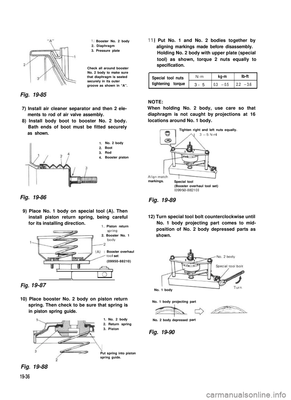
Fig. 19-85
1. Booster No. 2 body2. Diaphragm
3. Pressure plate
Check all around boosterNo. 2 body to make surethat diaphragm is seatedsecurely in its outergroove as shown in “A”.
7) Install air cleaner separator and then 2 ele-
ments to rod of air valve assembly.
8) Install body boot to booster No. 2 body.
Bath ends of boot must be fitted securely
as shown.
Fig. 19-86
1.No. 2 body
2.Boot
3.Rod
4.Booster piston
9) Place No. 1 body on special tool (A). Then
install piston return spring, being careful
for its installing direction.1. Piston return
Fig.
2. Booster No. 1
:Booster overhaultool set
(09950-88210)
1
I
19-87
10) Place booster No. 2 body on piston return
spring. Then check to be sure that spring is
in piston spring guide.
Fig.. 19-88
1. No. 2 body
2. Return spring
3. Piston
\Put spring into pistonspring guide.
11) Put No. 1 and No. 2 bodies together by
aligning markings made before disassembly.
Holding No. 2 body with upper plate (special
tool) as shown, torque 2 nuts equally to
specification.
Special tool nutsN.mkg-mlb-ft
tightening torque3-50.3 - 0.52.2 - 3.6
NOTE:
When holding No. 2 body, use care so that
diaphragm is not caught by projections at 16
locations around No. 1 body.
ml
Tighten right and left nuts equally.
A 3-5N.m
markings.Special tool(Booster overhaul tool set)(08850-88210)
Fig. 19-89
12) Turn special tool bolt counterclockwise until
No. 1 body projecting part comes to mid-
position of No. 2 body depressed parts as
shown.
No. 1 body
No. 1 body projecting part
No. 2 bodydepressedpart
Fig. 19-90
19-36