1987 MAZDA 626 fuse
[x] Cancel search: fusePage 1752 of 1865
AUTO ADJUSTING SUSPENSION (AAS) 1 5
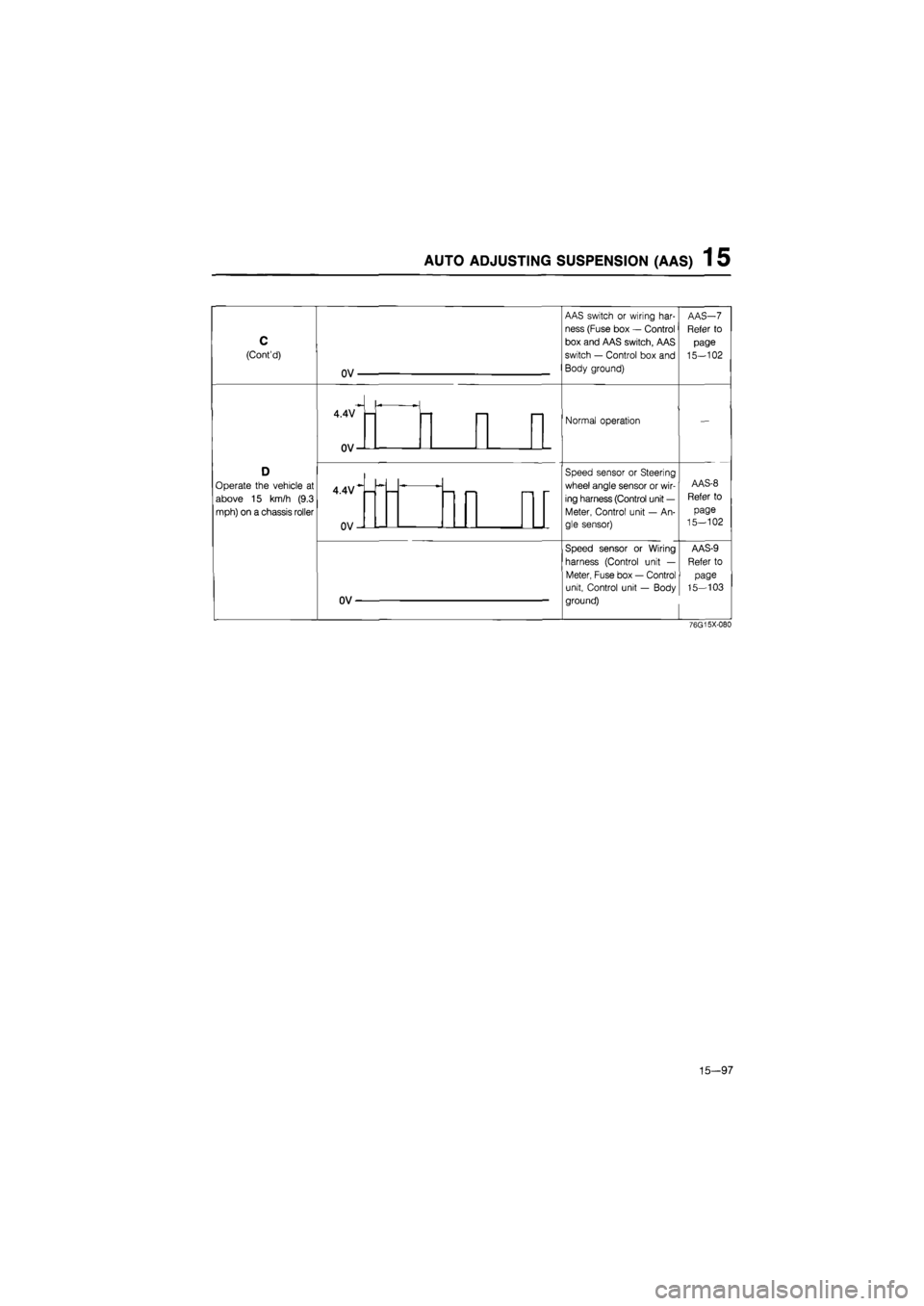
C
(Cont'd)
Operate
the
vehicle
at
above
15 km/h (9.3
mph) on
a
chassis roller
OV-
4.4V
0V-
4.4V
OV-
OV
AAS switch
or
wiring har-
ness (Fuse box
—
Control
box and AAS switch, AAS
switch
—
Control box and
Body ground)
Normal operation
Speed sensor
or
Steering
wheel angle sensor
or
wir-
ing harness (Control unit
—
Meter, Control unit
—
An-
gle sensor)
Speed sensor
or
Wiring
harness (Control unit
—
Meter, Fuse box
—
Control
unit, Control unit
—
Body
ground)
76G15X-080
15-97
Page 1754 of 1865
AUTO ADJUSTING SUSPENSION
(AAS) 1 5
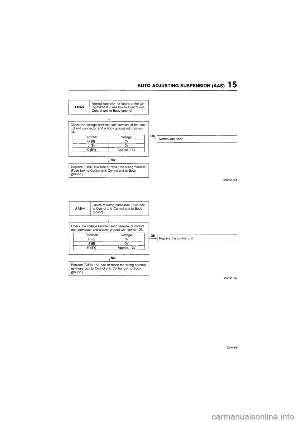
AAS-3
Normal operation
or
failure
of
the wir-ing harness (Fuse box
to
Control unit, Control unit
to
Body ground)
Check the voltage between each terminal
of
the con-trol unit connector and
a
body ground with ignition ON.
Terminal Voltage
G(B) OV
J(B) OV
K (BY) Approx.
12V
OK
Normal operation.
NG
Replace TURN 15A fuse
or
repair the wiring harness (Fuse box
to
Control unit, Control unit
to
Body ground.)
86U15X-161
AAS-4
Failure
of
wiring harnesses (Fuse
box
to Control unit, Control unit
to
Body
ground).
Check the voltage between each terminal
of
control unit connector and
a
body ground with ignition
ON.
Terminals Voltage
G (B) OV
J (B) OV
K (BY)
ADDTOX.
12V
OK
Replace the control unit.
NG
Replace TURN 15A fuse
or
repair the wiring harness-
es (Fuse box
to
Control unit, Control unit
to
Body
ground.)
86U15X-162
15-99
Page 1755 of 1865
1 5 AUTO ADJUSTING SUSPENSION (AAS)
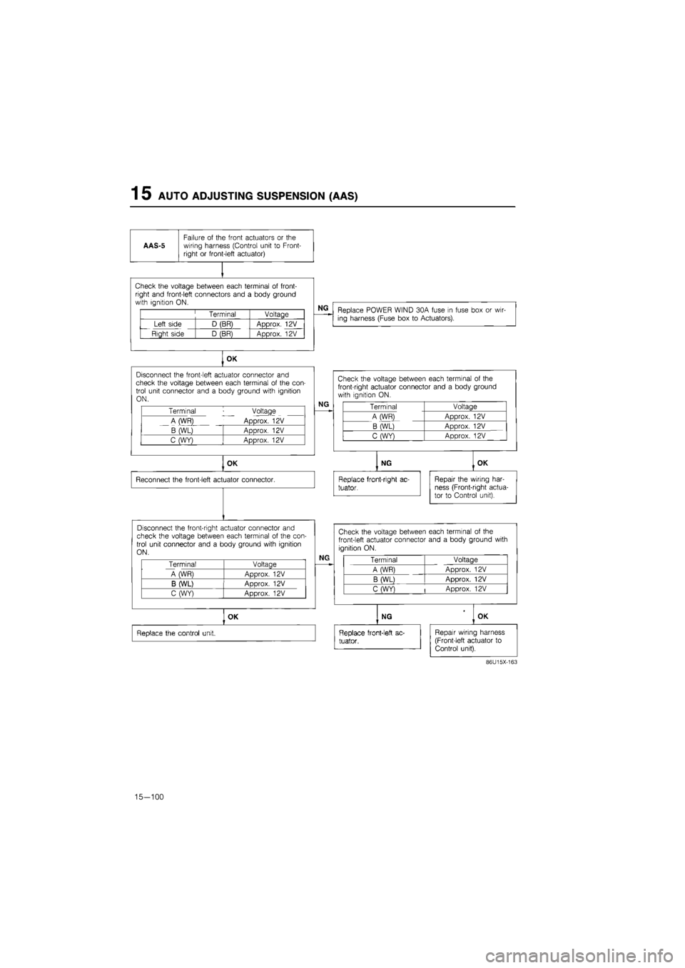
AAS-5
Failure
of
the front actuators
or the
wiring harness (Control unit
to
Front-right
or
front-left actuator)
Check the voltage between each terminal
of
front-right and front-left connectors and
a
body ground with ignition ON.
Terminal Voltage
Left side D (BR) Approx.
12V
Right side D (BR) Approx.
12V
NG
Replace POWER WIND 30A fuse
in
fuse box
or
wir-ing harness (Fuse box
to
Actuators).
OK
Disconnect the front-left actuator connector
and
check the voltage between each terminal
of
the con-trol unit connector and
a
body ground with ignition ON.
Terminal Voltage
A (WR) Approx.
12V
B (WL) Approx.
12V
C (WY) Approx.
12V
NG
OK
Reconnect the front-left actuator connector.
Disconnect the front-right actuator connector and check the voltage between each terminal
of
the con-trol unit connector and
a
body ground with ignition ON.
Terminal Voltage
A WR) Aoorox.
12V
B (WL) ADDrox.
12V
C (WY) Approx.
12V
Check the voltage between each terminal
of the
front-right actuator connector and
a
body ground with ignition
ON.
Terminal Voltage
A (WR) Approx.
12V
B (WL) Approx.
12V
C (WY) Approx.
12V
NG
Replace front-right
ac-
tuator.
OK
Repair the wiring har-ness (Front-right actua-tor
to
Control unit).
NG
Check the voltage between each terminal
of
the
front-left actuator connector and
a
body ground with
ignition ON.
Terminal Voltage
A (WR) Approx.
12V
B (WL) Approx.
12V
C (WY)
|
Approx.
12V
OK
Replace the control unit.
NG OK
Replace front-left
ac-
tuator.
Repair wiring harness (Front-left actuator
to
Control unit).
86U15X-163
15-100
Page 1756 of 1865
AUTO ADJUSTING SUSPENSION (AAS) 1 5
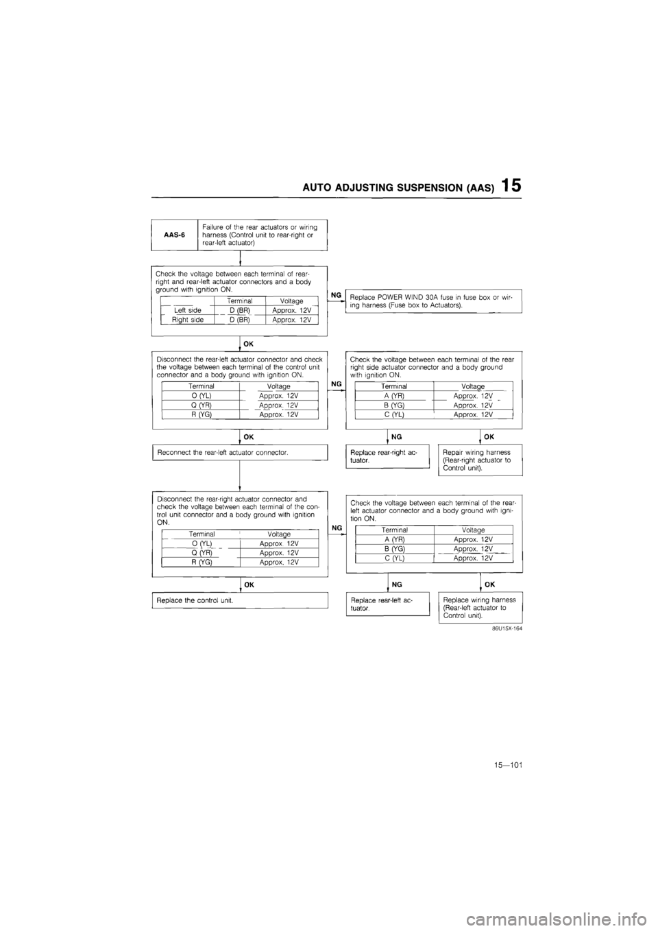
AAS-6
Failure
of
the rear actuators
or
wiring harness (Control unit
to
rear-right
or
rear-left actuator)
vi i11 1vuuuyu tw/v^ii I^CI^I i id i i in I«I wi i
right and rear-left actuator connectors and
a
body ground with ignition ON.
Terminal Voltage
Left side D (BR) Approx.
12V
Right side D (BR) Approx.
12V
NG
Replace POWER WIND 30A fuse
in
fuse box
or
wir-ing harness (Fuse box
to
Actuators).
OK
Disconnect the rear-left actuator connector and check the voltage between each terminal
of
the control unit connector and
a
body ground with ignition ON.
Terminal Voltage
0 (YL) Approx.
12V
Q (YR) Approx.
12V
R (YG) Approx.
12V
NG
OK
Reconnect the rear-left actuator connector.
Disconnect the rear-right actuator connector and check the voltage between each terminal
of
the con-trol unit connector and
a
body ground with ignition ON.
Terminal
'
Voltage
0 (YL)
ADDrox 12V
Q (YR)
ADDrox. 12V
R (YG} Approx.
12V
NG
OK
Replace the control unit.
Check the voltage between each terminal
of
the rear right side actuator connector and
a
body ground with ignition ON.
Terminal Voltage
A (YR) Approx.
12V
B (YG) Approx.
12V
C (YL) Approx.
12V
NG
Replace rear-right ac-
tuator,
OK
Repair wiring harness (Rear-right actuator
to
Control unit).
Check the voltage between each terminal
of
the rear-left actuator connector and
a
body ground with igni-tion ON.
Terminal Voltaae
A (YR) Approx.
12V
B (YG) ADDrox.
12V
C (YL) Approx.
12V
NG
Replace rear-1 eft
ac-
tuator.
OK
Replace wiring harness (Rear-left actuator
to
Control unit).
86U15X-164
15—101
Page 1757 of 1865
1 5 AUTO ADJUSTING SUSPENSION
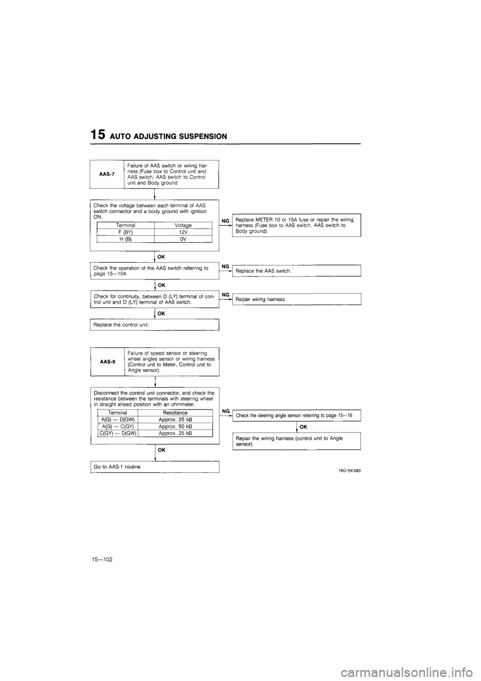
AAS-7
Failure
of
AAS switch
or
wiring har-ness (Fuse box
to
Control unit and AAS switch, AAS switch
to
Control unit and Body ground
Check the voltage between each terminal
of
AAS switch connector and
a
body ground with ignition ON.
Terminal Voltage
F (BY) 12V
H (B) OV
NG Replace METER
10 or
15A fuse
or
repair the wiring harness (Fuse box
to
AAS switch, AAS switch
to
Body ground).
OK
Check the operation
of
the AAS switch referring
to
page 15—104.
, OK
Check
for
continuity, between
D
(LY) terminal
of
con-
trol unit and
D
(LY) terminal
of
AAS switch.
OK
Replace the control unit.
A AS-8
Failure
of
speed sensor
or
steering wheel angles sensor
or
wiring harness (Control unit
to
Meter, Control unit
to
Angle sensor).
NG
Replace the AAS switch.
NG
Repair wiring harness.
Disconnect the control unit connector, and check the resistance between the terminals with steering wheel in straight ahead position with
an
ohmmeter.
Terminal Resistance
A(G)
-
D(GW) Approx.
25
k£2
' A(G}
-
C(GY) Approx.
50 kfl
C(GY)
-
D(GW) Approx.
25
kJ2
NG
Check the steering angle sensor referring
to
page 15—16
OK
Go
to
AAS-1 routine.
OK
Repair the wiring harness (control unit
to
Angle
sensor).
76G15X-083
15-102
Page 1758 of 1865
AUTO ADJUSTING SUSPENSION 1 5
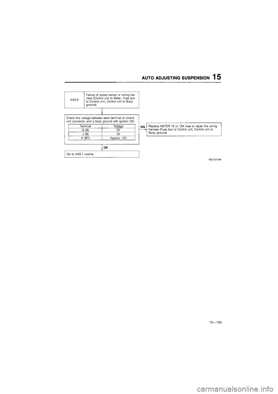
AAS-9
Failure of speed sensor or wiring har-ness (Control unit to Meter, Fuse box to Control unit, Control unit to Body ground)
Replace METER 10 or 15A fuse or repair the wiring harness (Fuse box to Control unit, Control unit to Body ground).
Check the voltage between each terminal of control
unit connector and a body ground with ignition ON.
Terminal Voltage
G (B) OV
J (B) OV
K (BY) Approx. 12V
OK
Go to AAS-1 routine.
76G15X-084
15—103
Page 1761 of 1865
1 5 POWER DOOR LOCK
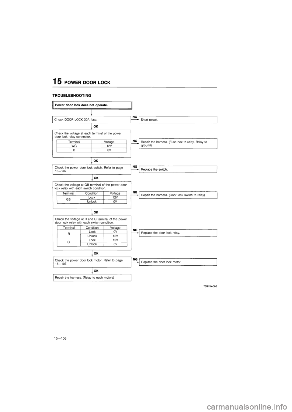
TROUBLESHOOTING
Terminal Voltage
WG 12V
B OV
Check the voltage
at GB
terminal
of
the power door lock relay with each switch condition.
Terminal Condition Voltage
GB Lock 12V GB Unlock OV
OK
Check the voltage
at R
and
G
terminal
of
the power door lock relay with each switch condition.
Terminal Condition Voltaae
R Lock OV R Unlock 12V
G Lock 12V G Unlock OV
Power door lock does not operate.
Check DOOR LOCK 30A fuse.
OK
NG
Short circuit.
Check the voltage
at
each terminal
of
the power door lock relay connector.
NG
Repair the harness. (Fuse box
to
relay, Relay
to
ground)
OK
Check the power door lock switch. Refer
to
page 15-107.
OK
NG
Replace the switch.
NG
Repair the harness. (Door lock switch
to
relay)
NG
Replace the door lock relay.
OK
Check the power door lock motor. Refer
to
page
15-107.
OK
Repair the harness. (Relay
to
each motors)
NG
Replace the door lock motor.
76G15X086
15—106
Page 1788 of 1865
OUTLINE 16
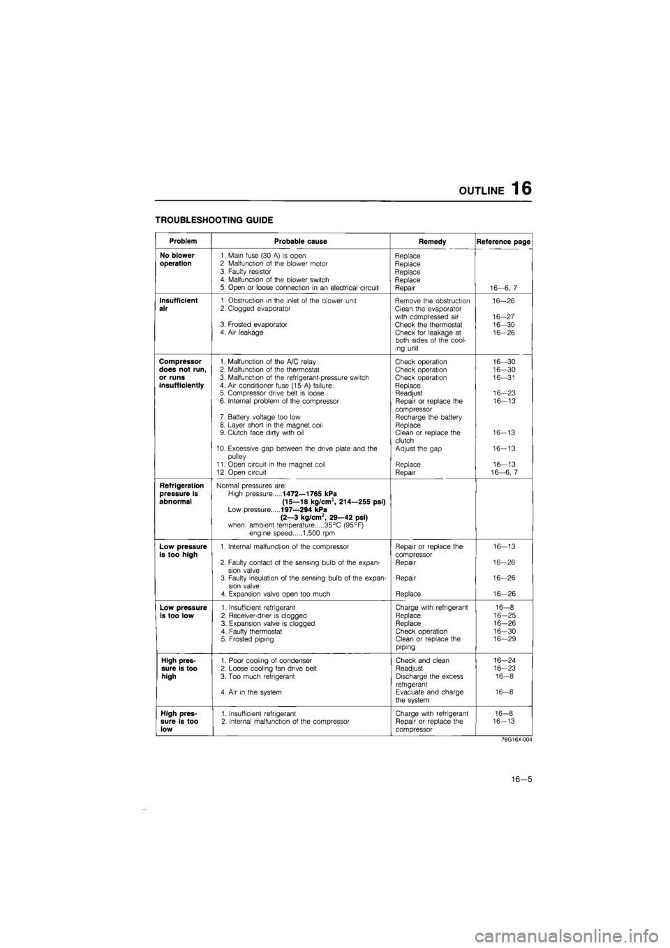
TROUBLESHOOTING GUIDE
Problem Probable cause Remedy Reference page
No blower
1. Main fuse (30
A) is
open Replace
operation
2 Malfunction
of
the blower motor Replace 3. Faulty resistor Replace 4. Malfunction
of
the blower switch Replace 5. Open
or
loose connection
in an
electrical circuit Repair 16—6,
7
Insufficient
1. Obstruction
in
the inlet
of
the blower unit Remove the obstruction 16-26
air
2. Clogged evaporator Clean the evaporator
with compressed
air
16-27 3. Frosted evaporator Check the thermostat 16-30 4. Air leakage Check for leakage
at
16-26 both sides
of
the cool-
ing unit
Compressor
1. Malfunction
of
the A/C relay Check operation 16—30
does not run,
2. Malfunction
of
the thermostat Check operation 16—30
or runs
3. Malfunction
of
the refrigerant-pressure switch Check operation 16—31
insufficiently
4.
Air
conditioner fuse (15
A)
failure Replace 5. Compressor drive belt
is
loose Readjust 16—23
6. Internal problem
of
the compressor Repair
or
replace
the
16—13
compressor 7. Battery voltage too low Recharge the battery 8. Layer short
in
the magnet coil Replace 9. Clutch face dirty with
oil
Clean
or
replace the 16-13
clutch 10. Excessive gap between the drive plate and
the
Adjust the gap 16-13
pulley
11. Open circuit
in
the magnet coil Replace 16—13
12 Open circuit Repair 16-6,
7
Refrigeration
Normal pressures are:
pressure is
High pressure
1472—1765 kPa
abnormal (15—18 kg/cm2, 214—255 psi)
Low pressure
197—294 kPa
(2—3 kg/cm2, 29—42 psi)
when: ambient temperature 35°C (95°F)
engine speed 1,500
rpm
Low pressure
1. Internal malfunction
of
the compressor Repair
or
replace the 16-13
is too high
compressor
2. Faulty contact
of
the sensing bulb
of
the expan-Repair 16-26
sion valve 3. Faulty insulation
of
the sensing bulb
of
the expan-Repair 16—26
sion valve
4. Expansion valve open too much Replace 16—26
Low pressure
1. Insufficient refrigerant Charge with refrigerant 16-8
is too low
2. Receiver-drier
is
clogged Replace 16-25
3. Expansion valve
is
clogged Replace 16-26
4. Faulty thermostat Check operation 16-30 5. Frosted piping Clean
or
replace the 16—29
piping
High pres-
1. Poor cooling
of
condenser Check and clean 16-24
sure is too
2. Loose cooling fan drive belt Readjust 16—23
high
3. Too much refrigerant Discharge the excess 16-8
refrigerant 4.
Air in
the system Evacuate and charge 16-8
the system
High pres-
1. Insufficient refrigerant Charge with refrigerant 16-8
sure is too
2. Internal malfunction
of
the compressor Repair
or
replace the 16-13
low
compressor
76G16X-004
16—5