Page 1230 of 1865
7C ASSEMBLY
76G07C-311
76G07C-312
76G07C-313
12. Install the speedometer driven gear.
Tightening torque:
8—11 Nm (80—110 cm-kg, 69—95 in-lb)
13. Install the oil level gauge and tube along with a new
O-ring to the transaxle case.
Tightening torque:
7—10 N m (70—100 cm-kg, 61-87 in-lb)
14. Install a new O-ring on the vacuum diaphragm.
15. Select the proper diaphragm rod.
(1) Measure the N dimension with the SST and
a scale.
(2) Select the diaphragm rod in accordance with
the table below.
N dimension Applicable diaphragm
rod
length
Below 25.4 mm (1.000
in)
29.5
mm
(1.161
in)
25.4—25.9
mm
(1.000-1.020
in)
30.0
mm
(1.181
in)
25.9—26.4
mm
(1.020-1.039
in)
30.5
mm
(1.200
in)
26.4—26.9
mm
(1.039-1.059
in)
31.0
mm
(1.220
in)
26.9 mm (1,059 in)
or
over 31.5
mm
(1.240
in)
16. Install the vacuum diaphragm.
76G07C-314
7C—116
Page 1236 of 1865

7C INSTALLATION
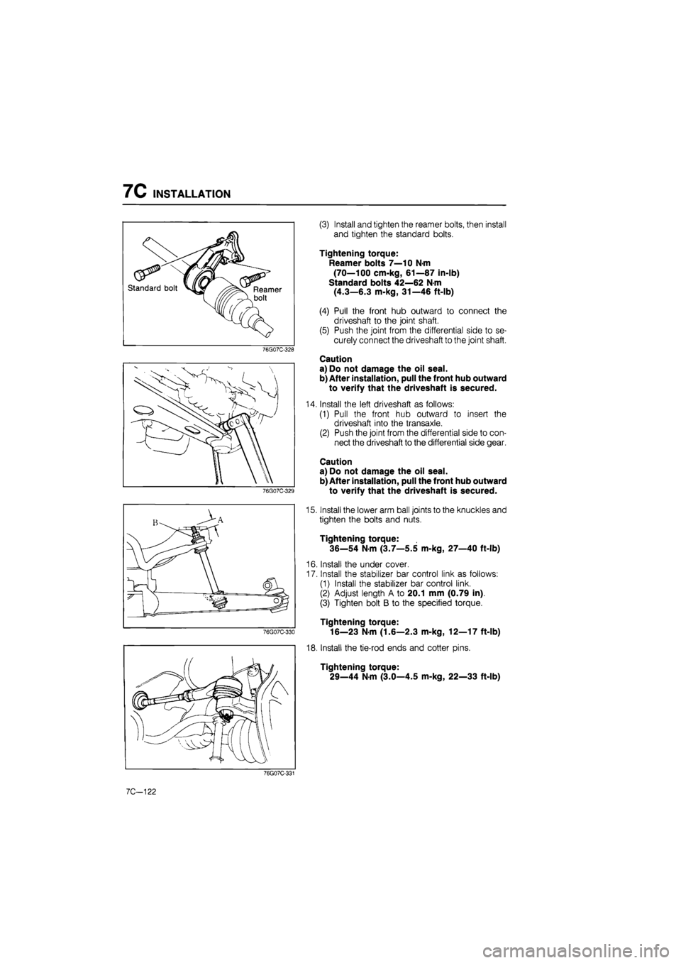
(3) Install and tighten the reamer bolts, then install
and tighten the standard bolts.
Tightening torque:
Reamer bolts 7—10 N-m
(70—100 cm-kg, 61—87 in-lb)
Standard bolts 42—62 N m
(4.3—6.3 m-kg, 31—46 ft-lb)
(4) Pull the front hub outward to connect the
driveshaft to the joint shaft.
(5) Push the joint from the differential side to se-
curely connect the driveshaft to the joint shaft.
Caution
a) Do not damage the oil seal.
b) After installation, pull the front hub outward
to verify that the driveshaft is secured.
Install the left driveshaft as follows:
(1) Pull the front hub outward to insert the
driveshaft into the transaxle.
(2) Push the joint from the differential side to con-
nect the driveshaft to the differential side gear.
Caution
a) Do not damage the oil seal.
b) After installation, pull the front hub outward
to verify that the driveshaft is secured.
Install the lower arm ball joints to the knuckles and
tighten the bolts and nuts.
Tightening torque:
36—54 N-m (3.7—5.5 m-kg, 27—40 ft-lb)
Install the under cover.
Install the stabilizer bar control link as follows:
(1) Install the stabilizer bar control link.
(2) Adjust length A to 20.1 mm (0.79 in).
(3) Tighten bolt B to the specified torque.
Tightening torque:
16—23 N-m (1.6—2.3 m-kg, 12—17 ft-lb)
Install the tie-rod ends and cotter pins.
Tightening torque:
29—44 N-m (3.0—4.5 m-kg, 22—33 ft-lb)
7C-122
Page 1255 of 1865
9 OUTLINE
Rear Axle (4WS)
86U09X-004
1. Lock nut 4. Knuckle spindle
2. Disc plate 5. Wheel speed sensor (ABS)
3. Dust cover 6. Shock absorber
SPECIFICATIONS
—-— Engine model
Item """ ~'
F6, F8, RF-N FE, RF-CX —-— Engine model
Item """ ~' Right Left Right Left
Length of joint mm (in)
(between centers of joints)
MTX 368.5 (14.51) 368.5 (14.51) 360.0 (14.17) 360.0 (14.17) Length of joint mm (in)
(between centers of joints) ATX 359.5 (14.15) 359.5 (14.15) 355.5 (14.00) 355.5 (14.00)
Shaft diameter mm (in) MTX 23.0 (0.91) 24.0 (0.94) Shaft diameter mm (in) ATX 23.0 (0.91) 24.0 (0.94)
76G09X-001
86U09X-082
9—6
Page 1313 of 1865
STEERING WHEEL AND COLUMN 1 0
il 9
^ J /
Disassembly Note
Steering lock
Use a chisel to make a groove
in
the head of the steer-
ing lock installation screws. Remove the screws with
a screwdriver; then remove the steering lock.
86U10X-44
Assembly Note
Steering lock
Install the steering lock on the jacket; then use new
steering lock mounting screws, and tighten them until
the heads break off.
Caution
Check the operation of the lock while tight-
ening the steering lock mounting screws.
86U10X-045
INSPECTION
Check the following and replace any faulty parts.
Shaft 1. Wear of column bushing
86U10X-046
2. Length of steering column
Length:
614—616 mm (24.2—24.3 in)
3. Damage of column
86U10X-047
10—25
Page 1396 of 1865

1 1 OUTLINE
SPECIFICATIONS
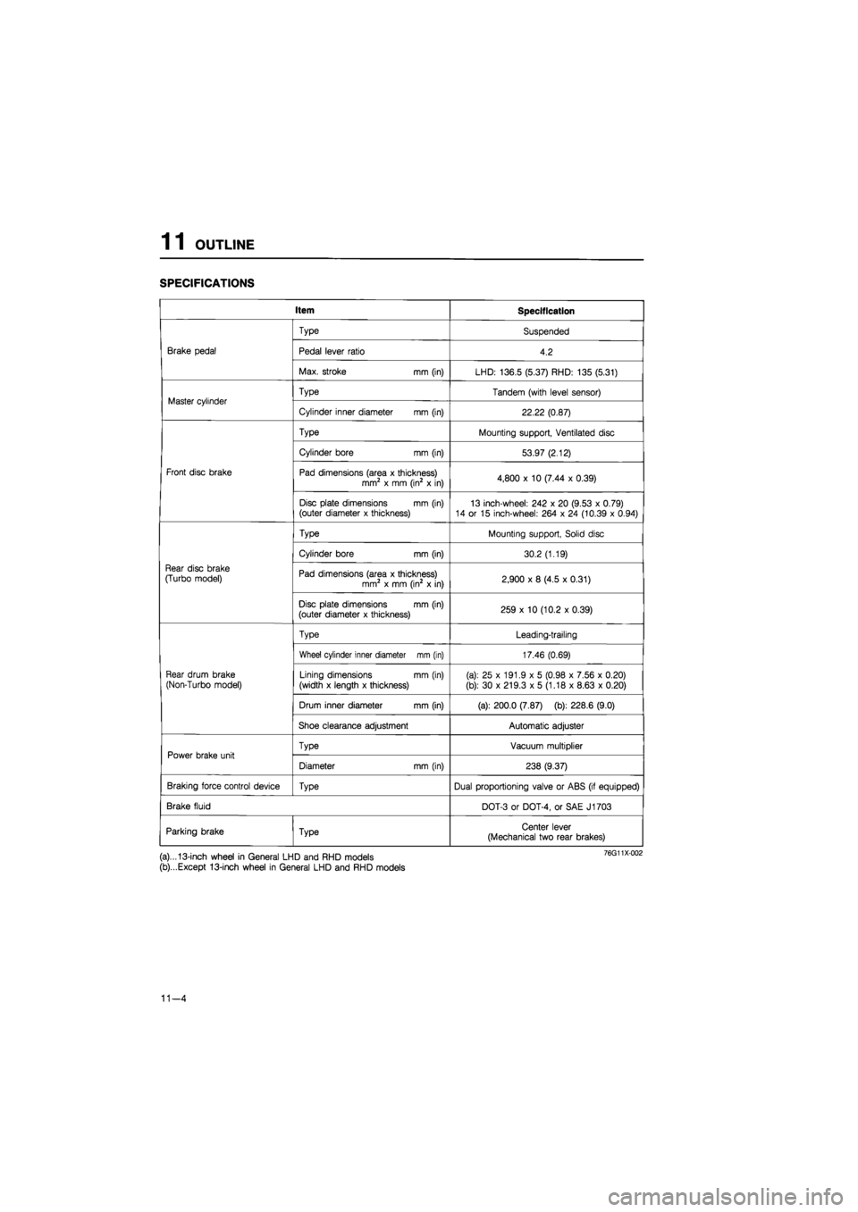
Item Specification
Brake pedal
Type Suspended
Brake pedal Pedal lever ratio 4.2 Brake pedal
Max. stroke mm (in) LHD: 136.5 (5.37) RHD: 135 (5.31)
Master cylinder Type Tandem (with level sensor) Master cylinder
Cylinder inner diameter mm (in) 22.22 (0.87)
Front disc brake
Type Mounting support, Ventilated disc
Front disc brake
Cylinder bore mm (in) 53.97 (2.12)
Front disc brake Pad dimensions (area x thickness) mm2 x mm (in2 x in) 4,800 x 10 (7.44 x 0.39) Front disc brake
Disc plate dimensions mm (in) (outer diameter x thickness) 13 inch-wheel: 242 x 20 (9.53 x 0.79) 14 or 15 inch-wheel: 264 x 24 (10.39 x 0.94)
Rear disc brake
(Turbo model)
Type Mounting support, Solid disc
Rear disc brake
(Turbo model)
Cylinder bore mm (in) 30.2 (1.19)
Rear disc brake
(Turbo model) Pad dimensions (area x thickness) mm2 x mm (in2 x in) 2,900 x 8 (4.5 x 0.31)
Rear disc brake
(Turbo model)
Disc plate dimensions mm (in) (outer diameter x thickness) 259 x 10 (10.2 x 0.39)
Rear drum brake
(Non-Turbo model)
Type Leading-trailing
Rear drum brake
(Non-Turbo model)
Wheel cylinder inner diameter mm (in) 17.46 (0.69)
Rear drum brake
(Non-Turbo model) Lining dimensions mm (in)
(width x length x thickness) (a): 25 x 191.9 x 5 (0.98 x 7.56 x 0.20)
(b): 30 x 219.3 x 5 (1.18 x 8.63 x 0.20)
Rear drum brake
(Non-Turbo model)
Drum inner diameter mm (in) (a): 200.0 (7.87) (b): 228.6 (9.0)
Rear drum brake
(Non-Turbo model)
Shoe clearance adjustment Automatic adjuster
Power brake unit Type Vacuum multiplier Power brake unit
Diameter mm (in) 238 (9.37)
Braking force control device Type Dual proportioning valve or ABS (if equipped)
Brake fluid DOT-3 or DOT-4, or SAE J1703
Parking brake Type Center lever (Mechanical two rear brakes)
(a)...13-inch wheel in General LHD and RHD models
(b)...Except 13-inch wheel in General LHD and RHD models
11-4
Page 1417 of 1865
MASTER CYLINDER 1 1
Adjustment
Adjust the piston to push rod clearance in the follow-
ing order.
1. For (a) of judgement table
(1) Measure the height of (D) and record after
removing the SST from the master cylinder.
76G11X-028
Adjust nut
(2) Install the SST again to the master cylinder,
and turn the adjust nut so that clearance (C)
between the SST and the master cylinder is
0 mm (Oin).
(3) Measure the height of (E) when clearance (C)
is 0 mm (Oin).
(E) — (D) = Projecting amount of the power
brake unit push rod
76G11X-029
(4) Remove the push rod from the power brake
unit.
63G11X-349
(5) Make the piston to push rod clearance 0 mm
(Oin) by turning the push rod and shortening
the push rod length by the amount of (E) — (D).
Note
The threads of the push rod are specially
designed so that the push rod bolt becomes
harder to turn past a certain point to prevent
loosening of the bolt. Turn the push rod bolt
only within this range when adjusting.
76G11X030
11—25
Page 1418 of 1865
1 1 MASTER CYLINDER
2. For (b) of the judgement table
(1) Push the push rod of SST lightly by hand until
the push rod end touches the bottom of the pri-
mary piston in the master cylinder.
Note
When pushing only use enough pressure to
bottom the rod in the piston. If too much pres-
sure is applied a false reading will occur.
76G11X-031
(2) Measure clearance (B) between the adjust nut
and the SST body with the rod held down.
(B) = Recessed amount of the power brake
unit push rod
76G11X-032
(3) Remove the push rod from the power brake
unit.
63G11X-353
(4) Make the push rod clearance 0 mm (Oin) by
turning the push rod and lengthening the push
rod length by the amount of (B).
Note
The threads of the push rod are specially
designed so that the push rod bolt becomes
harder to turn past a certain point to prevent
loosening of the bolt. Turn the push rod bolt
only within this range when adjusting.
76G11X-033
11—26
Page 1501 of 1865

13 OUTLINE
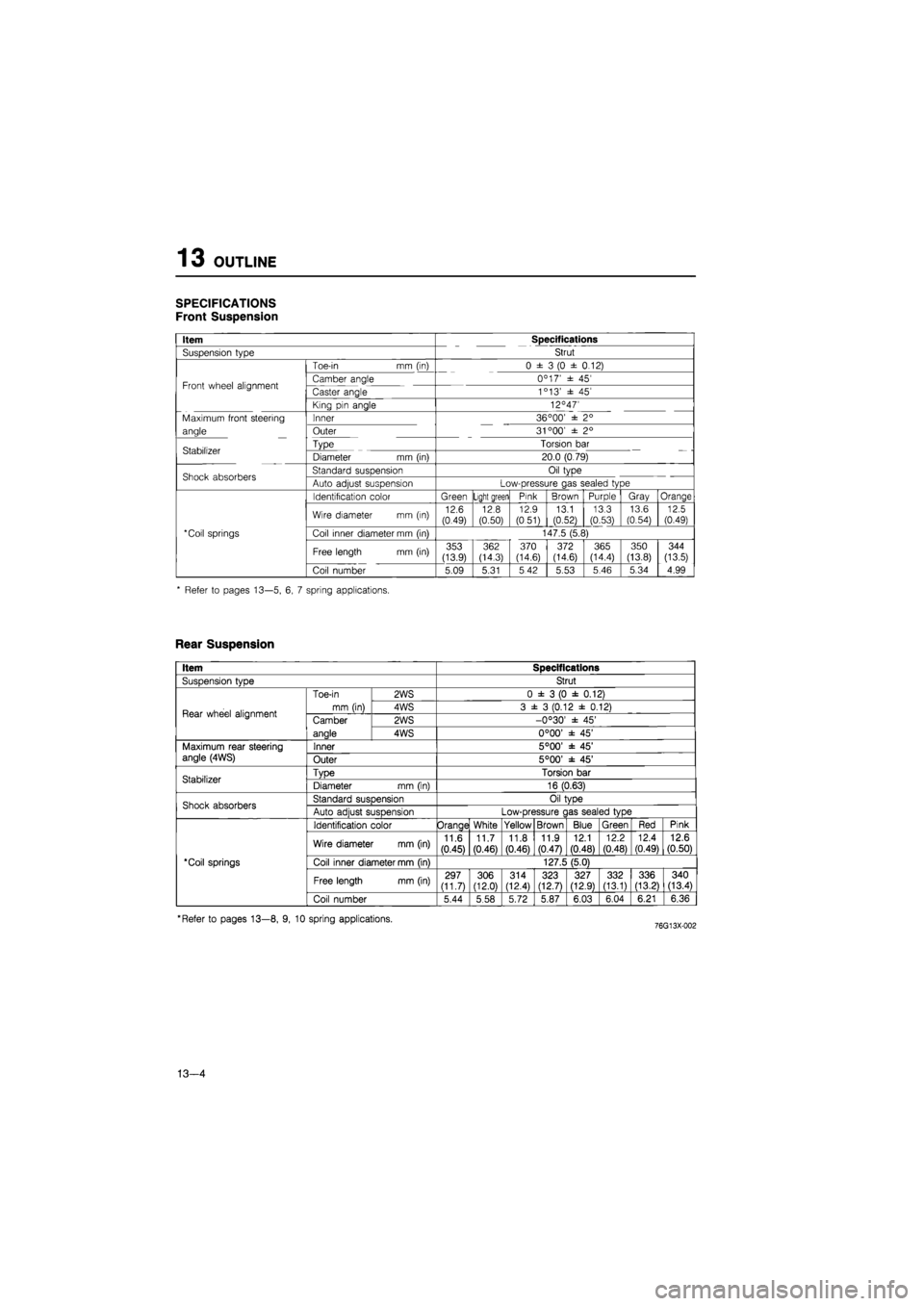
SPECIFICATIONS
Front Suspension
Item Specifications
Suspension type Strut
Toe-in mm (in) 0 ± 3 (0 ± 0.12)
Front wheel alignment Camber angle 0C 17' ± 45' Front wheel alignment Caster angle 1c 13' ± 45'
King pin angle 12°47'
Maximum front steering Inner 36 °00' ± 2°
angle Outer 31 °00' ± 2°
Stabilizer Type Torsion bar Stabilizer Diameter mm (in) 20.0 (0.79)
Shock absorbers Standard suspension Oil type Shock absorbers Auto adjust suspension Low-pressure gas sealed type
Identification color Green Light green Pink Brown Purple Gray Orange
Wire diameter mm (in) 12.6 (0.49) 12.8 (0.50)
12.9
(0.51) 13.1 (0.52)
13.3 (0.53)
13.6
(0.54) 12.5 (0.49)
*Coil springs Coil inner diameter mm (in) 147.5 (5.8)
Free length mm (in) 353 (13.9)
362 (14.3) 370 (14.6) 372 (14.6) 365 (14.4)
350
(13.8)
344
(13.5)
Coil number 5.09 5.31 5 42 5.53 5.46 5.34 4.99
* Refer to pages 13—5, 6, 7 spring applications.
Rear Suspension
Item Specifications
SusDension tvDe Strut
Rear wheel alignment
Toe-in
mm (in)
2WS 0 ± 3 (0 ± 0.12)
Rear wheel alignment
Toe-in
mm (in) 4WS 3 ± 3 (0.12 ± 0.12) Rear wheel alignment Camber
anale
2WS -0°30' ± 45' Rear wheel alignment Camber
anale 4WS 0°00' ± 45'
Maximum rear steering angle (4WS) Inner 5°00' ± 45' Maximum rear steering angle (4WS) Outer 5°00' ± 45'
Stabilizer TvDe Torsion bar Stabilizer Diameter mm (in) 16 (0.63)
Shock absorbers Standard susDension Oil tvDe Shock absorbers Auto adiust suspension Low-pressure c las sealed type
'Coil springs
Identification color Orange White Yellow Brown Blue Green Red Pink
'Coil springs
Wire diameter mm (in) 11.6
(0.45)
11.7 (0.46) 11.8
(0.46)
11.9 (0.47)
12.1
(0.48)
12.2
(0.48)
12.4 (0.49) 12.6 (0.50)
'Coil springs Coil inner diameter mm (in) 127.5 (5.0) 'Coil springs
Free length mm (in) 297 (11.7) 306 (12.0)
314 (12.4) 323 (12.7) 327 (12.9) 332 (13.1) 336 (13.21 340 (13.4)
'Coil springs
Coil number 5.44 5.58 5.72 5.87 6.03 6.04 6.21 6.36
'Refer to pages 13—8, 9, 10 spring applications.
13—4