Page 1135 of 1865

TROUBLESHOOTING 7C
Specified line pressure:
Range Pressure kPa (kg/cm2, psi) Range
Idle Stall
D 294-392 (3-4, 43-57) 883-1079 (9—11, 128-156)
2 785—1177 (8—12, 114—171) 785-1177 (8—12, 114-171)
1 294-392 (3-4, 43—57) 883-1079 (9—11, 128—156)
R 392-687 (4-7, 57-100) 1570—1864 (16—19, 228-270)
76G07C-031
Evaluation
Condition Possible cause
Below standard
In all ranges
Worn oil pump
Below standard
In all ranges Fluid leakage from the oil pump, control valve, or transaxle case
Below standard
In all ranges
Stuck pressure regulator valve Below standard
In D, 1, 2 ranges Fluid leakage from the rear clutch or governor hydraulic circuit, or both
Below standard
In R range only Fluid leakage from the low and reverse brake hydraulic circuit
Excessive line pressure at idle Leaking or disconnected vacuum hose Excessive line pressure at idle
Leaking vacuum diaphragm
76G07C-032
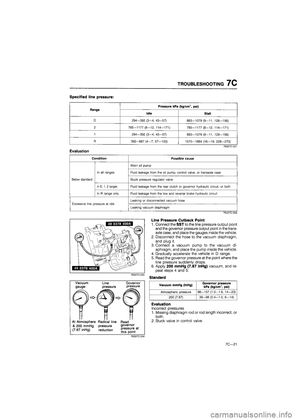
76G07C-033
Vacuum
gauge Line
pressure
Governor pressure
At Atmosphere Radical line Read
& 200 mmHg pressure governor
(7.87 inHg) reduction
Line Pressure Cutback Point
1. Connect the SST to the line pressure output point
and the governor pressure output point in the trans-
axle case, and place the gauges inside the vehicle.
2. Disconnect the hose to the vacuum diaphragm,
and plug it.
3. Connect a vacuum pump to the vacuum di-
aphragm, and place the pump inside the vehicle.
4. Gradually accelerate the vehicle in D range.
5. Read the governor pressure at the point where the
line pressure suddenly drops.
6. Apply 200 mmHg (7.87 inHg) vacuum, and re-
peat steps 4 and 5.
Standard
Vacuum mmHg (InHg) Governor pressure kPa (kg/cm2, psi)
Atmospheric pressure 98-157 (1.0—1.6, 14-23)
200 (7.87) 39-98 (0.4-1.0, 6—14)
Evaluation
Incorrect pressures
1. Missing diaphragm rod or rod length incorrect, or
both.
2. Stuck valve in control valve.
76G07C-034
7C—21
Page 1141 of 1865

ON-VEHICLE MAINTENANCE 7C
76G07C-045
fflfiirv T
5. Turn locknut A by hand until it just touches the
spacer.
6. Tighten locknut B to the specified torque.
Tightening torque:
8—11 N-m (80—110 cm-kg, 69—95 in-lb)
7. Verify that there is a click at each range when shift-
ed from P «-» 1 range.
8. Check that the positions of the selector lever and
the indicator are exact.
9. Check that the button returns smoothly when used
to shift the selector.
10. If necessary, check the spring.
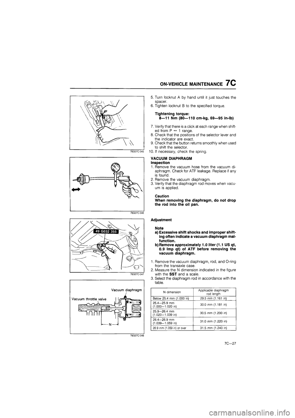
VACUUM DIAPHRAGM
Inspection
1. Remove the vacuum hose from the vacuum di-
aphragm. Check for ATF leakage. Replace if any
is found.
2. Remove the vacuum diaphragm.
3. Verify that the diaphragm rod moves when vacu-
um is applied.
Caution
When removing the diaphragm, do not drop
the rod into the oil pan.
76G07C-046
Vacuum diaphragm
Adjustment
Note
a) Excessive shift shocks and improper shift-
ing often indicate a vacuum diaphragm mal-
function.
b) Remove approximately 1.0 liter (1.1 US qt,
0.9 Imp qt) of ATF before removing the
vacuum diaphragm.
1. Remove the vacuum diaphragm, rod, and O-ring
from the transaxle case.
2. Measure the N dimension indicated in the figure
with the SST and a scale.
3. Select the diaphragm rod in accordance with the
table.
N dimension Applicable diaphragm
rod length
Below 25.4 mm (1.000 in) 29.5 mm (1.161 in)
25.4—25.9 mm (1.000-1.020 in) 30.0 mm (1.181 in)
25.9—26.4 mm (1.020-1.039 in) 30.5 mm (1.200 in)
26.4—26.9 mm
(1.039—1.059 in) 31.0 mm (1.220 in)
26.9 mm (1.059 in) or over 31.5 mm (1.240 in)
76G07C-048
10,-21
Page 1173 of 1865
INSPECTION AND REPAIR 7C
Piston
Remove the piston by blowing compressed air into
the hole indicated.
76G07C-142
76G07C-143
Inspection
Check the following and repair or replace any faulty
parts.
1. Drive and driven plates for damage or wear
Drive plate thickness
Standard: 1.6 mm (0.063 in)
Minimum: 1.4 mm (0.055 in)
2. Clutch piston for damage or cracks
3. Clutch drum for damage or deformation
4. Seal contact areas for damage
5. Check ball for leaking or sticking
6. Spring retainer for deformation
7. Broken or worn snap ring
8. Broken or weakened spring
Free length of spring:
26.2 mm (1.031 in)
9. Worn drum bushing
Drum bushing inner diameter:
44.075 mm (1.735 in) max.
76G07C-144
Assembly
1. Apply ATF to the inner seal ring, and install it into
the rear clutch drum.
2. Apply ATF to the outer seal ring, and install it onto
the piston.
3. Install the piston by pushing evenly around the cir-
cumference, being careful not to damage the seal
rings.
76G07C-145
7C—59
Page 1177 of 1865
INSPECTION AND REPAIR 7C
Piston
Remove the piston by blowing compressed air into
the fluid hole as shown.
76G07C-156
76G07C-157
76G07C-158
Inspection
Check the following and repair or replace any faulty
parts.
1. Drive and driven plates for damage or wear
Drive plate thickness
Standard: 1.6 mm (0.063 in)
Minimum: 1.4 mm (0.055 in)
2. Clutch piston for damage or cracks
3. Clutch drum for damage or deformation
4. Seal contact areas for damage
5. Check ball for leaking or sticking
6. Spring retainer for deformation
7. Broken or worn snap ring
8. Broken or weakened spring
Free length of spring:
26.2 mm (1.031 in)
Assembly
1. Apply ATF to the inner seal ring and install it into
the rear clutch drum.
2. Apply ATF to the outer seal ring, and install it onto
the piston.
3. Install the piston by pushing evenly around the cir-
cumference, being careful not to damage the seal
rings.
4. Install the return springs and spring retainer into
the piston.
76G07C-159
7C-63
Page 1184 of 1865
7C INSPECTION AND REPAIR
76G07C-181
Mr
76G07C-182
76G07C-183
Inspection
Check the following and replace any faulty parts.
1. Damaged or worn piston
2. Weakened return spring
Free length of spring:
FE engine: 48.0 mm (1.89 in)
F6 engine: 45.5 mm (1.79 in)
Assembly
1. Apply ATF to the inner and outer seal rings, and
install them onto the servo piston.
2. Apply ATF to the seal ring, and install it onto the
servo retainer.
3. Assemble the servo retainer and servo piston.
BRAKE BAND
Inspection
Check the following and replace any faulty part.
1. Damaged or worn brake band
76G07C-184
7C-70
Page 1185 of 1865

INSPECTION AND REPAIR 7C
76G07C-185
76G07C-186
76G07C-187
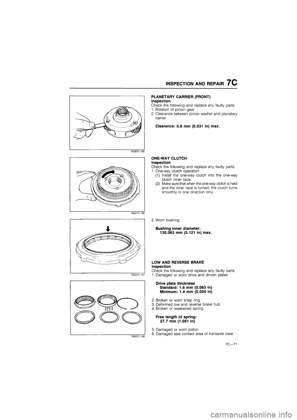
PLANETARY CARRIER (FRONT)
Inspection
Check the following and replace any faulty parts.
1. Rotation of pinion gear
2. Clearance between pinion washer and planetary
carrier
Clearance: 0.8 mm (0.031 in) max.
ONE-WAY CLUTCH
Inspection
Check the following and replace any faulty parts.
1. One-way clutch operation
(1) Install the one-way clutch into the one-way
clutch inner race.
(2) Make sure that when the one-way clutch is held
and the inner race is turned, the clutch turns
smoothly in one direction only.
2. Worn bushing
Bushing inner diameter:
130.063 mm (5.121 in) max.
76G07C-188
LOW AND REVERSE BRAKE
Inspection
Check the following and replace any faulty parts.
1. Damaged or worn drive and driven plates
Drive plate thickness
Standard: 1.6 mm (0.063 in)
Minimum: 1.4 mm (0.055 in)
2. Broken or worn snap ring
3. Deformed low and reverse brake hub
4. Broken or weakened spring
Free length of spring:
27.7 mm (1.091 in)
5. Damaged or worn piston
6. Damaged seal contact area of transaxle case
7C-71
Page 1186 of 1865

7C INSPECTION AND REPAIR
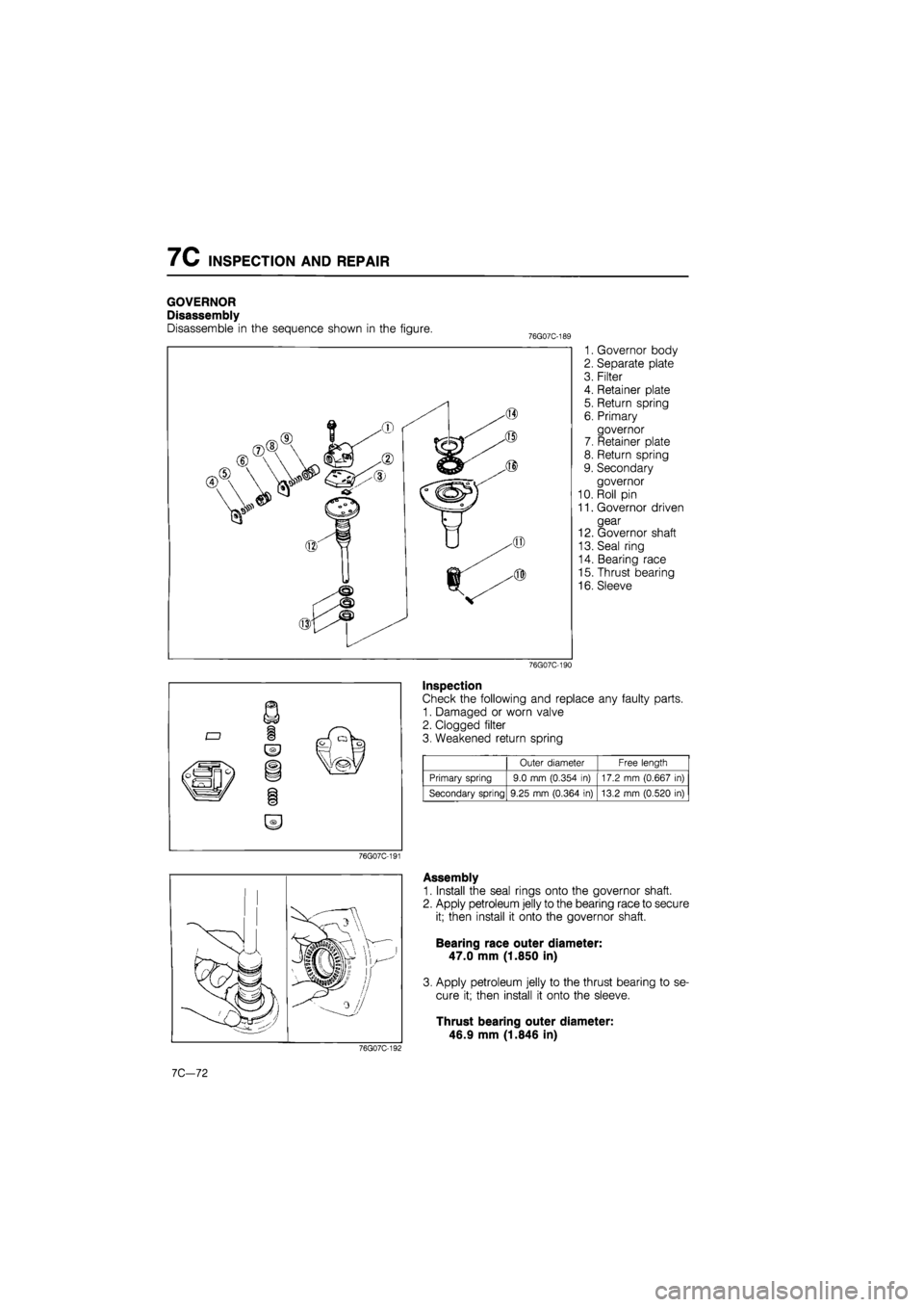
GOVERNOR
Disassembly
Disassemble in the sequence shown in the figure. 76G07C-1E
1. Governor body
2. Separate plate
3. Filter
4. Retainer plate
5. Return spring
6. Primary
governor
7. Retainer plate
8. Return spring
9. Secondary
governor
10. Roll pin
11. Governor driven
gear
12. Governor shaft
13. Seal ring
14. Bearing race
15. Thrust bearing
16. Sleeve
76G07C-190
Inspection
Check the following and replace any faulty parts.
1. Damaged or worn valve
2. Clogged filter
3. Weakened return spring
Outer diameter Free length
Primary spring 9.0 mm (0.354 in) 17.2 mm (0.667 in)
Secondary spring 9.25 mm (0.364 in) 13.2 mm (0.520 in)
76G07C-191
76G07C-192
7C-72
Assembly
1. Install the seal rings onto the governor shaft.
2. Apply petroleum jelly to the bearing race to secure
it; then install it onto the governor shaft.
Bearing race outer diameter:
47.0 mm (1.850 in)
3. Apply petroleum jelly to the thrust bearing to se-
cure it; then install it onto the sleeve.
Thrust bearing outer diameter:
46.9 mm (1.846 in)
Page 1190 of 1865
7C INSPECTION AND REPAIR
Inspection
Check the following and replace any faulty parts.
1. Damaged or worn valves
2. Damaged oil passage
3. Cracked or damaged valve body
4. Operation of each valve
5. Weakened spring 76go7c-2o2
Spring
Name Outer dia. mm (in) Free length mm (in) Wire dia. mm (in)
Throttle backup 7.3 (0.287) 36.0 (1.417) 0.8 (0.031)
Downshift 5.55 (0.219) 21.9 (0.862) 0.55 (0.022)
2-3 shift 6.9 (0.272) 41.0 (1.614) 0.7 (0.028)
1-2 shift 6.4 (0.252) 31.63 (1.245) 0.4 (0.016)
Second lock 5.55 (0.219) 33.5 (1.319) 0.55 (0.022)
Pressure regulator 11.7 (0.461) 43.0 (1.693) 1.2 (0.047)
Throttle relief 7.0 (0.276) 11.2 (0.441) 0.9 (0.035)
Orifice check 5.0 (0.197) 15.5 (0.610) 0.23 (0.009)
76G07C-203
Valve Location
63U07B-500
7C-76