Page 1549 of 1865

13 REAR WHEEL ALIGNMENT
76G13X-033
86U13X-116
86U13X-117
86U13X-116
13-52
REAR WHEEL ALIGNMENT
PRE-INSPECTION
1. Check the tire inflation and bring to the recom-
mended pressure.
2. Inspect the wheel and tire runout.
3. The vehicle must be on level ground and have no
luggage or passenger load.
4. Check that the suspension is correctly adjusted.
5. The difference in height between the left and right
sides from the center of the wheel to the fender
rim should be within 10 mm (0.39 in).
Caution
a) Front and rear wheel alignments should be
checked simultaneously. If adjustment is
made to either the front or rear wheels,
recheck the alignment, particularly toe-in,
on all other wheels.
b) Check and adjust the steering angle trans-
fer shaft after adjusting the rear wheel align-
ment. (Refer to Section 10.)
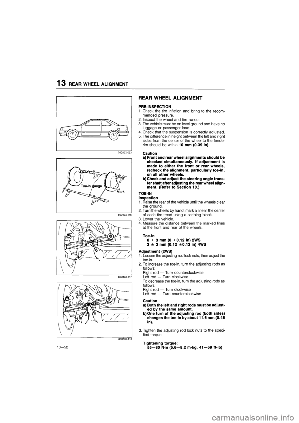
TOE-IN
Inspection
1. Raise the rear of the vehicle until the wheels clear
the ground.
2. Turn the wheels by hand, mark a line in the center
of each tire tread using a scribing block.
3. Lower the vehicle.
4. Measure the distance between the marked lines
at the front and rear of the wheels.
Toe-in
0 ± 3 mm (0 ±0.12 in) 2WS
3 ± 3 mm (0.12 ±0.12 in) 4WS
Adjustment (2WS)
1. Loosen the adjusting rod lock nuts, then adjust the
toe-in.
2. To increase the toe-in, turn the adjusting rods as
follows:
Right rod — Turn counterclockwise
Left rod — Turn clockwise
To decrease the toe-in, turn the adjusting rods as
follows:
Right rod — Turn clockwise
Left rod — Turn counterclockwise
Caution
a) Both the left and right rods must be adjust-
ed by the same amount.
b) One turn of the adjusting rod (both sides)
changes the toe-in by about 11.6 mm (0.46
in).
3. Tighten the adjusting rod lock nuts to the speci-
fied torque.
Tightening torque:
55—80 N-m (5.6—8.2 m-kg, 41—59 ft-lb)
Page 1550 of 1865
REAR WHEEL ALIGNMENT 13
86U13X-119
Adjustment (4WS)
To adjust the toe-in, loosen the left and right tie-rod
locknuts, and turn the tie-rods by the same amount.
Caution
a) The left and right tie-rods are both right
threaded, so, to increase the toe-in, turn the
right tie-rod toward the front of the vehicle,
and turn the left tie-rod by the same amount
toward the rear.
b) One turn of the tie-rod (both sides) changes
the toe-in by about 7.8 mm (0.31 in).
c) Adjust the toe-in after adjusting the steer-
ing angle.
Tighten the tie-rod locknuts to the specified torque.
Tightening torque: 69—98 N-m
(7—10 m-kg, 51—72 ft-lb)
86U13X-120
CAMBER
Preparation
1. Remove the center caps from the wheels.
2. Uncrimp the locknut and remove it.
86U13X-121
Inspection
1. Install the SST to the driveshaft.
86U13X-122
13—53
Page 1555 of 1865
14 BONNET
76G14X-605
76G14X-606
9 ± 1.5 mm (0.36 ± 0.06 in)
(a)
4 ± 1 mm
(0.66 ± 0.04 in)
(b)
76G14X-607
INSTALLATION
Install in the reverse order of removal, noting the fol-
lowing:
1. Bonnet hinge installation bolts
Tightening torque:
19—25 N-m (1.9—2.6 m-kg, 14—19 ft-lb)
2. Push the fasteners into the bonnet.
ADJUSTMENT
Bonnet
Adjust the bonnet laterally and vertically by loosen-
ing the bonnet to hinge mounting bolts and reposi-
tioning the bonnet.
Bonnet Lock
Adjust the bonnet lock after the bonnet has been
aligned. The lock can be moved vertically and
horizontally. Align it with the striker on the bonnet af-
ter loosening the mounting bolts.
Tightening torque:
7.8—11 N-m (0.8—1.1 m-kg, 5.8—8.0 ft-lb)
76G14X-608
14—4
Page 1558 of 1865
TRUNK LID 14
4. Remove the fasteners and remove the rear pack-
age tray.
86U14X-017
INSTALLATION
Install in the reverse order of removal.
Tightening torque:
86U14X-018
14—7
Page 1559 of 1865
14 TRUNK LID
86U14X-019
86U14X-020
ADJUSTMENT
Trunk Lid
1. Adjust the trunk lid by loosening the lid to hinge
mounting bolts and repositioning it.
2. Align the trunk lid evenly as shown in the figure.
Trunk Lid Striker
1. Loosen the striker mounting bolts.
2. Tighten the bolts after adjusting.
Tightening torque:
7.8—11 N m (0.8—1.1 m-kg, 5.8—8.0 ft-lb)
86U14X-021
14—8
Page 1572 of 1865
REAR DOORS 1 4
9. Remove the door glass upward.
86U14X-051
Remove the mounting bolts, and remove the win-
dow regulator through the service hole.
Remove the window motor mounting bolts, then
remove the motor from the regulator (power
window).
86U14X052
INSTALLATION
Install in the reverse order of removal, noting the fol-
lowing.
Tightening torque:
Nm (m-kg, ft-lb)
Door lock assembly 4.22-6 18 (0 43-0 63, 3,10—4.54)
Outer handle 8.8-13 (0.9-1.3. 6.5-9.4)
Glass Quide 7.8—11 (0.8—1.1, 5.8—8.0)
Regulator Nut 8 8—13 (0.9—1.3, 6.5—9.4) Regulator Bolt 7.8-11 (0.8-1.1. 5.8-8.0)
Door lock striker 18-26 (1.8-2.7, 13-20)
Before installing the motor, connect the leads to a bat-
tery and run regulator down to the position shown.
14—21
Page 1575 of 1865
1 4 FRONT BUMPER
86U14X-057
86U14X-058
REMOVAL
1. Remove the under cover mounting screws.
2. Remove the bumper mounting screws.
3. Remove the front side bumper stay mounting nuts.
INSTALLATION
Install the front side bumper stay mounting nuts and
tighten the stay mounting nuts.
Tightening torque:
31—46 N-m (3.2—4.7 m-kg, 23—34 ft-lb)
76G14X-037
14—24
Page 1577 of 1865
1 4 REAR BUMPER
\
1 '
4 / t i4 / t- / i
86U14X-061
86U14X-062
REMOVAL
1. Remove the screws shown in the figure.
2. Remove the bumper mounting nuts.
3. Remove the nuts and fasteners shown in the fig-
ure and remove the reinforcement and bumper
stay from the bumper.
INSTALLATION
Install in the reverse order of removal.
Tightening torque:
Bumper stay installation nuts:
31—46 N m (3.2—4.7 m-kg, 23—34 ft-lb)
76G14X-004
14-26