Page 1611 of 1865
1 4 REAR HATCH GLASS
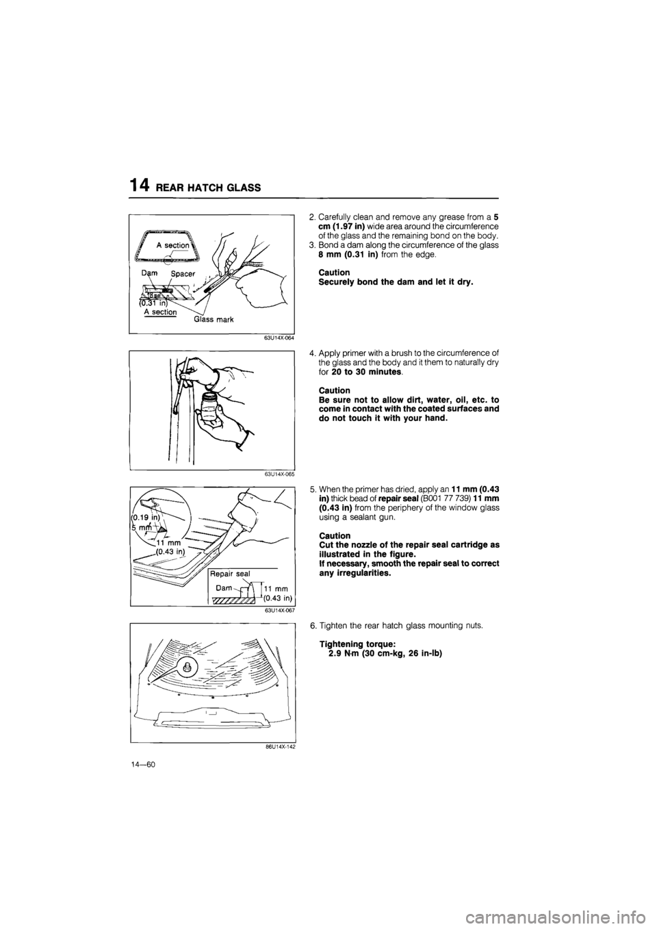
2. Carefully clean and remove any grease from a 5
cm (1.97 in) wide area around the circumference
of the glass and the remaining bond on the body.
3. Bond a dam along the circumference of the glass
8 mm (0.31 in) from the edge.
Caution
Securely bond the dam and let it dry.
63U14X-064
4. Apply primer with a brush to the circumference of
the glass and the body and
it
them to naturally dry
for 20 to 30 minutes.
Caution
Be sure not to allow dirt, water, oil, etc. to
come in contact with the coated surfaces and
do not touch it with your hand.
63U14X-065
5. When the primer has dried, apply an 11 mm (0.43
in) thick bead of repair seal (B001 77 739) 11 mm
(0.43 in) from the periphery of the window glass
using a sealant gun.
Caution
Cut the nozzle of the repair seal cartridge as
illustrated in the figure.
If necessary, smooth the repair seal to correct
any irregularities.
63U14X-067
6. Tighten the rear hatch glass mounting nuts.
Tightening torque:
2.9 N-m (30 cm-kg, 26 in-lb)
86U14X-142
14—60
Page 1631 of 1865
14 INSTRUMENT PANEL
INSTALLATION
Install in the reverse order of removal, noting the fol-
lowing.
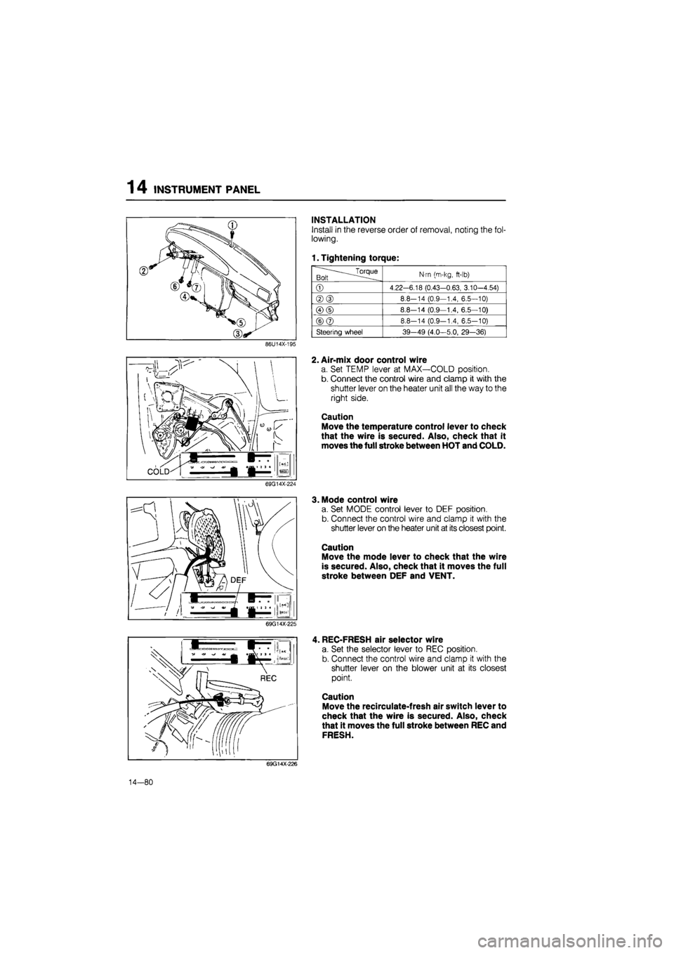
1. Tightening torque:
.^Torque Bolt
N-m (m-kg,
ft-lb)
©
4.22-6.18 (0.43-0.63, 3.10-4.54)
®(D
8.8-14 (0.9—1.4, 6.5—10)
©(D
8.8—14 (0.9—1.4, 6.5—10)
©@
8.8-14 (0.9-1.4, 6.5-10)
Steering wheel 39-49 (4.0—5.0, 29—36)
86U14X-195
2. Air-mix door control wire
a. Set TEMP lever at MAX—COLD position.
b. Connect the control wire and clamp it with the
shutter lever on the heater unit all the way to the
right side.
Caution
Move the temperature control lever to check
that the wire is secured. Also, check that it
moves the full stroke between HOT and COLD.
69G14X-224
3. Mode control wire
a. Set MODE control lever to DEF position.
b. Connect the control wire and clamp it with the
shutter lever on the heater unit at its closest point.
Caution
Move the mode lever to check that the wire
is secured. Also, check that it moves the full
stroke between DEF and VENT.
69G14X-225
, REC-FRESH air selector wire
a. Set the selector lever to REC position.
b. Connect the control wire and clamp it with the
shutter lever on the blower unit at its closest
point.
Caution
Move the recirculate-fresh air switch lever to
check that the wire is secured. Also, check
that it moves the full stroke between REC and
FRESH.
69G14X-226
14—80
Page 1640 of 1865
SLIDING SUNROOF 14
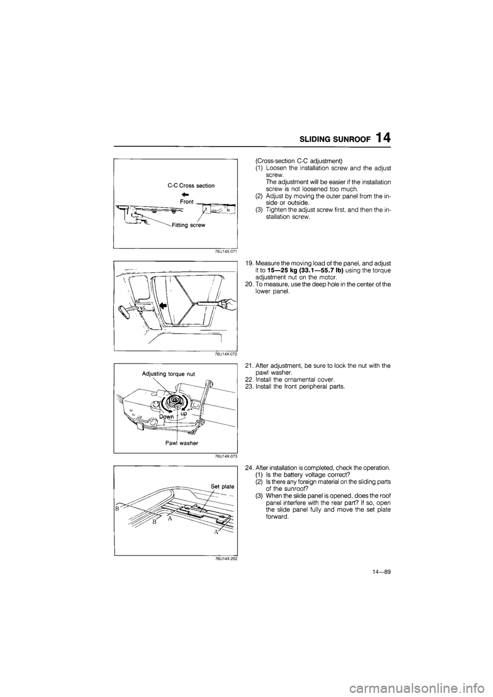
(Cross-section C-C adjustment)
(1) Loosen the installation screw and the adjust
screw.
The adjustment will be easier if the installation
screw is not loosened too much.
(2) Adjust by moving the outer panel from the in-
side or outside.
(3) Tighten the adjust screw first, and then the in-
stallation screw.
76U14X-071
19. Measure the moving load of the panel, and adjust
it to 15—25 kg (33.1—55.7 lb) using the torque
adjustment nut on the motor.
20. To measure, use the deep hole in the center of the
lower panel.
76U14X-072
Adjusting torque nut
Pawl washer
21. After adjustment, be sure to lock the nut with the
pawl washer.
22. Install the ornamental cover.
23. Install the front peripheral parts.
76U14X-073
24. After installation is completed, check the operation.
(1) Is the battery voltage correct?
(2) Is there any foreign material on the sliding parts
of the sunroof?
(3) When the slide panel is opened, does the roof
panel interfere with the rear part? If so, open
the slide panel fully and move the set plate
forward.
76U14X-202
14—89
Page 1651 of 1865
1 4 SEAT
69G14X-228
INSPECTION
Inspection of Front Seat
1. Check that the seat adjuster lever and recliner
knuckle lever move smoothly.
2. Check the seat mounting bolts for looseness. If
necessary, tighten the bolts to the specified torque.
Tightening torque:
Seat mounting bolt: 38—51 N-m
(3.9—5.2 m-kg, 28—38 ft-lb)
3. Apply grease to the moving parts.
4. Check the seat adjuster lever for wear.
REAR SEAT (Sedan and Coupe/MX-6)
Removal
1. Push the locks as shown in the figure to release
the cushion, then lift the seat cushion out.
76G14X048
2. Remove the end bolts, and lift the seat back off
the hooks.
69G14X-236
14—100
3. Remove the fastener.
4. Remove the seat back.
Installation
Install in the reverse order of removal.
Note
Tightening torque:
Seat back:
16—23 N-m (1.6—2.3 m-kg, 12—17 ft-lb)
Page 1802 of 1865
COMPRESSOR 16
Escape groove
^ / / / / j / / ' / / / / /
' / / I / /
1 \ \ x Suction \ \ \/ valve
n W: \ / / y /
I u
Piston— ^
69G16X-044
69G16X-045
Installation of Front Cylinder Head
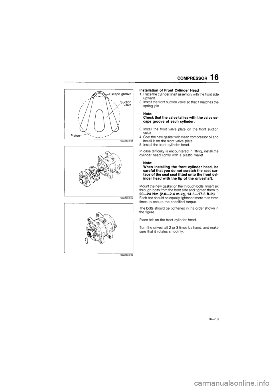
1. Place the cylinder shaft assembly with the front side
upward.
2. Install the front suction valve so that it matches the
spring pin.
Note:
Check that the valve tallies with the valve es-
cape groove of each cylinder.
3. Install the front valve plate on the front suction
valve.
4. Coat the new gasket with clean compressor oil and
install it on the front valve plate.
5. Install the front cylinder head.
In case difficulty is encountered in fitting, install the
cylinder head lightly with a plastic mallet.
Note:
When installing the front cylinder head, be
careful that you do not scratch the seat sur-
face of the seal seat fitted onto the front cyl-
inder head with the lip of the driveshaft.
Mount the new gasket on the through-bolts. Insert six
through-bolts from the front side and tighten them to
20—24 N m (2.0—2.4 m-kg, 14.5—17.3 ft-lb)
Each bolt should be equally tightened more than three
times to ensure the specified torque.
The bolts should be tightened in the order shown in
the figure.
Place felt on the front cylinder head.
Turn the driveshaft 2 or 3 times by hand, and make
sure that it rotates smoothly.
69G16X046
16—19
Page 1803 of 1865
16 COMPRESSOR
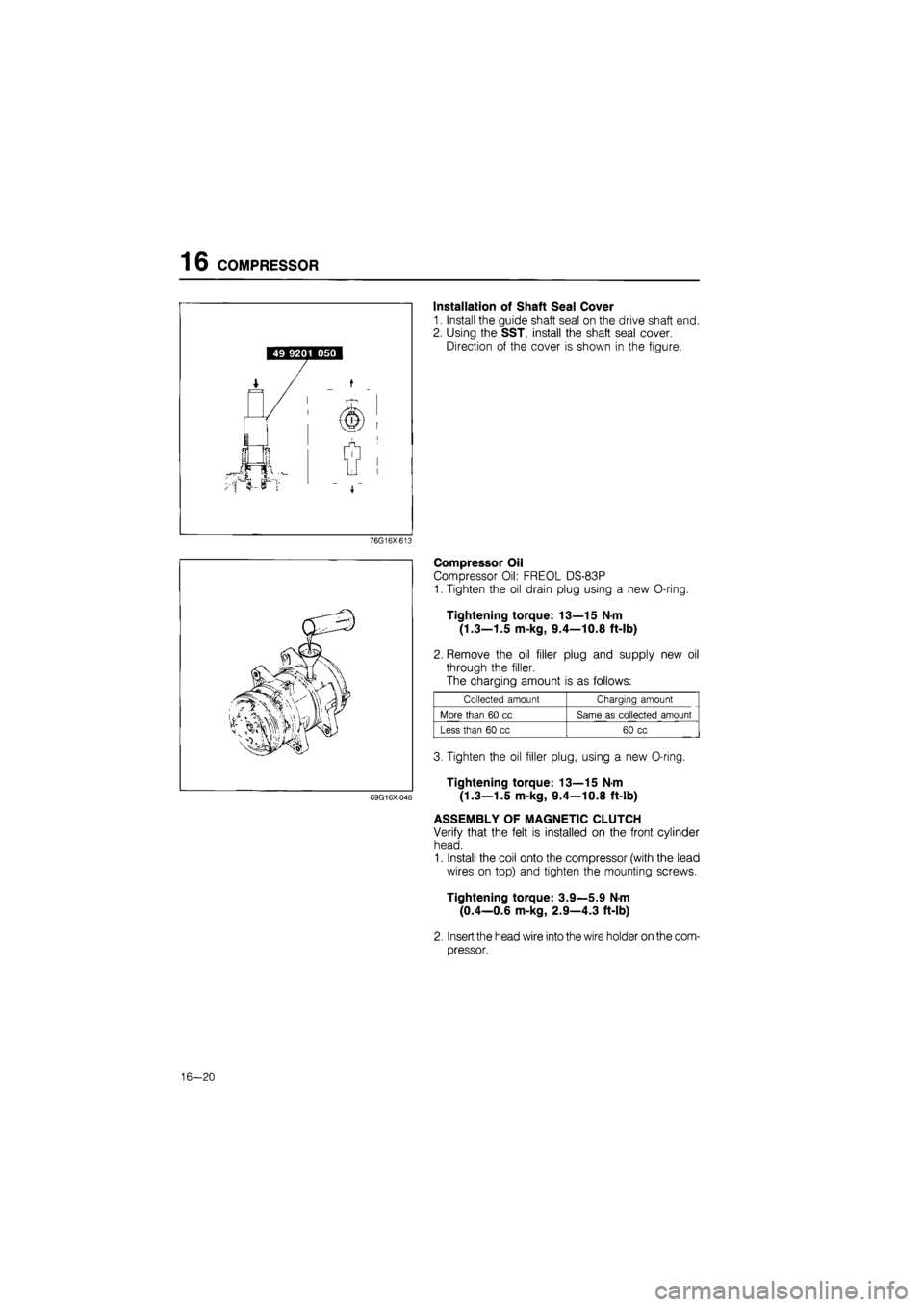
Installation of Shaft Seal Cover
1. Install the guide shaft seal on the drive shaft end.
2. Using the SST, install the shaft seal cover.
Direction of the cover is shown in the figure.
76G16X-613
69G16X-048
Compressor Oil
Compressor Oil: FREOL DS-83P
1. Tighten the oil drain plug using a new O-ring.
Tightening torque: 13—15 N-m
(1.3—1.5 m-kg, 9.4—10.8 ft-lb)
2. Remove the oil filler plug and supply new oil
through the filler.
The charging amount is as follows:
Collected amount Charging amount
More than
60 cc
Same
as
collected amount
Less than
60 cc
60
cc
3. Tighten the oil filler plug, using a new O-ring.
Tightening torque: 13—15 N-m
(1.3—1.5 m-kg, 9.4—10.8 ft-lb)
ASSEMBLY OF MAGNETIC CLUTCH
Verify that the felt is installed on the front cylinder
head.
1. Install the coil onto the compressor (with the lead
wires on top) and tighten the mounting screws.
Tightening torque: 3.9—5.9 N-m
(0.4—0.6 m-kg, 2.9—4.3 ft-lb)
2. Insert the head wire into the wire holder on the com-
pressor.
16—20
Page 1804 of 1865
COMPRESSOR 16
3. Install the pulley assembly by using the SST, then
install the cover and the snap ring.
76G16X-614
4. Install the drive plate onto the drive shaft together
with the original shim(s).
5. Using the SST (49 9201 010) to prevent the drive
plate rotation, tighten the bolt. (Refer to page
16-14.)
Tightening torque: 14—16 N-m
(1.4—1.6 m-kg, 10.1—11.5 ft-lb)
76G16X-009
6. Check that clutch clearance is between 0.3—0.6
mm (0.01—0.02 in). Adjust clearance by using
shim(s), if necessary. Adjusting shims are availa-
ble in the following thicknesses:
0.1 mm (0.0039 in)
0.3 mm (0.0118 in)
0.5 mm (0.0197 in)
Standard clearance:
0.3—0.6 mm (0.01—0.02 in)
69G16X-051
16—21
Page 1807 of 1865
16 CONDENSER
CONDENSER
ON-VEHICLE INSPECTION
1. Check the condenser fins for blockage or damage.
If the fins are clogged, clean them with compressed air.
If the fins are bent, straighten them with a screwdriver or pair of pliers.
2. Check the condenser fittings for leakage.
Repair or replace, if necessary.
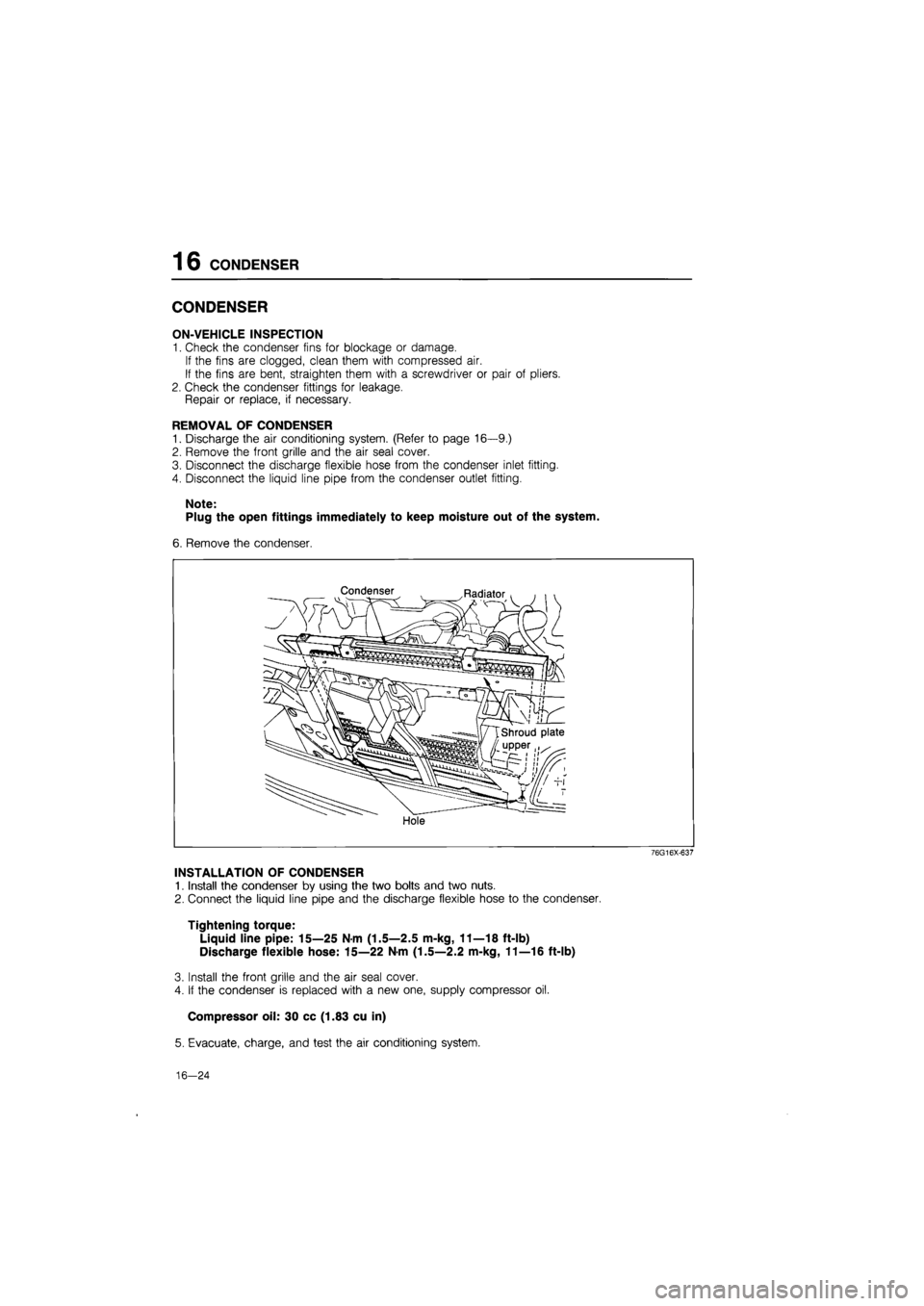
REMOVAL OF CONDENSER
1. Discharge the air conditioning system. (Refer to page 16—9.)
2. Remove the front grille and the air seal cover.
3. Disconnect the discharge flexible hose from the condenser inlet fitting.
4. Disconnect the liquid line pipe from the condenser outlet fitting.
Note:
Plug the open fittings immediately to keep moisture out of the system.
6. Remove the condenser.
Condenser Radiator
Hole
76G16X-637
INSTALLATION OF CONDENSER
1. Install the condenser by using the two bolts and two nuts.
2. Connect the liquid line pipe and the discharge flexible hose to the condenser.
Tightening torque:
Liquid line pipe: 15—25 Nm (1.5—2.5 m-kg, 11—18 ft-lb)
Discharge flexible hose: 15—22 N-m (1.5—2.2 m-kg, 11—16 ft-lb)
3. Install the front grille and the air seal cover.
4. If the condenser is replaced with a new one, supply compressor oil.
Compressor oil: 30 cc (1.83 cu in)
5. Evacuate, charge, and test the air conditioning system.
16—24