1987 MAZDA 626 torque
[x] Cancel search: torquePage 1808 of 1865
RECEIVER-DRIER 16
RECEIVER-DRIER
ON-VEHICLE INSPECTION
1. Use a leak detector to check the sight glass, the
fusible plug, and the fittings for leakage.
Repair or replace, if necessary.
2. Check the receiver-drier for clogging.
a) Run the engine at fast idle with the air conditioner
on.
b) Check both inlet and outlet temperatures.
If there is a great difference between the two tem-
peratures, replace the receiver-drier.
76G16X-622
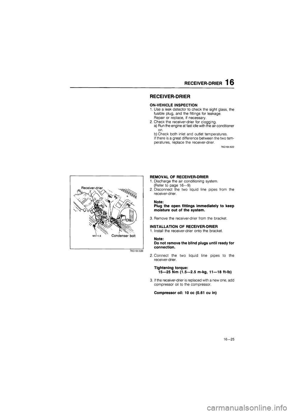
Receiver-drier
Condenser bolt
76G16X-638
REMOVAL OF RECEIVER-DRIER
1. Discharge the air conditioning system.
(Refer to page 16—9)
2. Disconnect the two liquid line pipes from the
receiver-drier.
Note:
Plug the open fittings immediately to keep
moisture out of the system.
3. Remove the receiver-drier from the bracket.
INSTALLATION OF RECEIVER-DRIER
1. Install the receiver-drier onto the bracket.
Note:
Do not remove the blind plugs until ready for
connection.
2. Connect the two liquid line pipes to the
receiver-drier.
Tightening torque:
15—25 N m (1.5—2.5 m-kg, 11—18 ft-lb)
3.
If
the receiver-drier is replaced with a new one, add
compressor oil to the compressor.
Compressor oil: 10 cc (0.61 cu in)
16-25
Page 1810 of 1865
COOLING UNIT 1 6
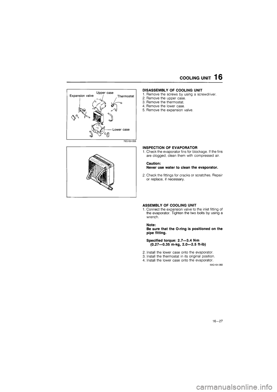
Upper case Expansion valve / Thermostat
Lower case
76G16X-006
DISASSEMBLY OF COOLING UNIT
1. Remove the screws by using a screwdriver.
2. Remove the upper case.
3. Remove the thermostat.
4. Remove the lower case.
5. Remove the expansion valve.
INSPECTION OF EVAPORATOR
1. Check the evaporator fins for blockage. If the fins
are clogged, clean them with compressed air.
Caution:
Never use water to clean the evaporator.
2. Check the fittings for cracks or scratches. Repair
or replace, if necessary.
ASSEMBLY OF COOLING UNIT
1. Connect the expansion valve to the inlet fitting of
the evaporator. Tighten the two bolts by using a
wrench.
Note:
Be sure that the O-ring is positioned on the
pipe fitting.
Specified torque: 2.7—3.4 N-m
(0.27—0.35 m-kg, 2.0—2.5 ft-lb)
2. Install the lower case onto the evaporator.
3. Install the thermostat in its original position.
4. Install the lower case onto the evaporator.
69G16X-060
16—27
Page 1811 of 1865
1 6 COOLING UNIT
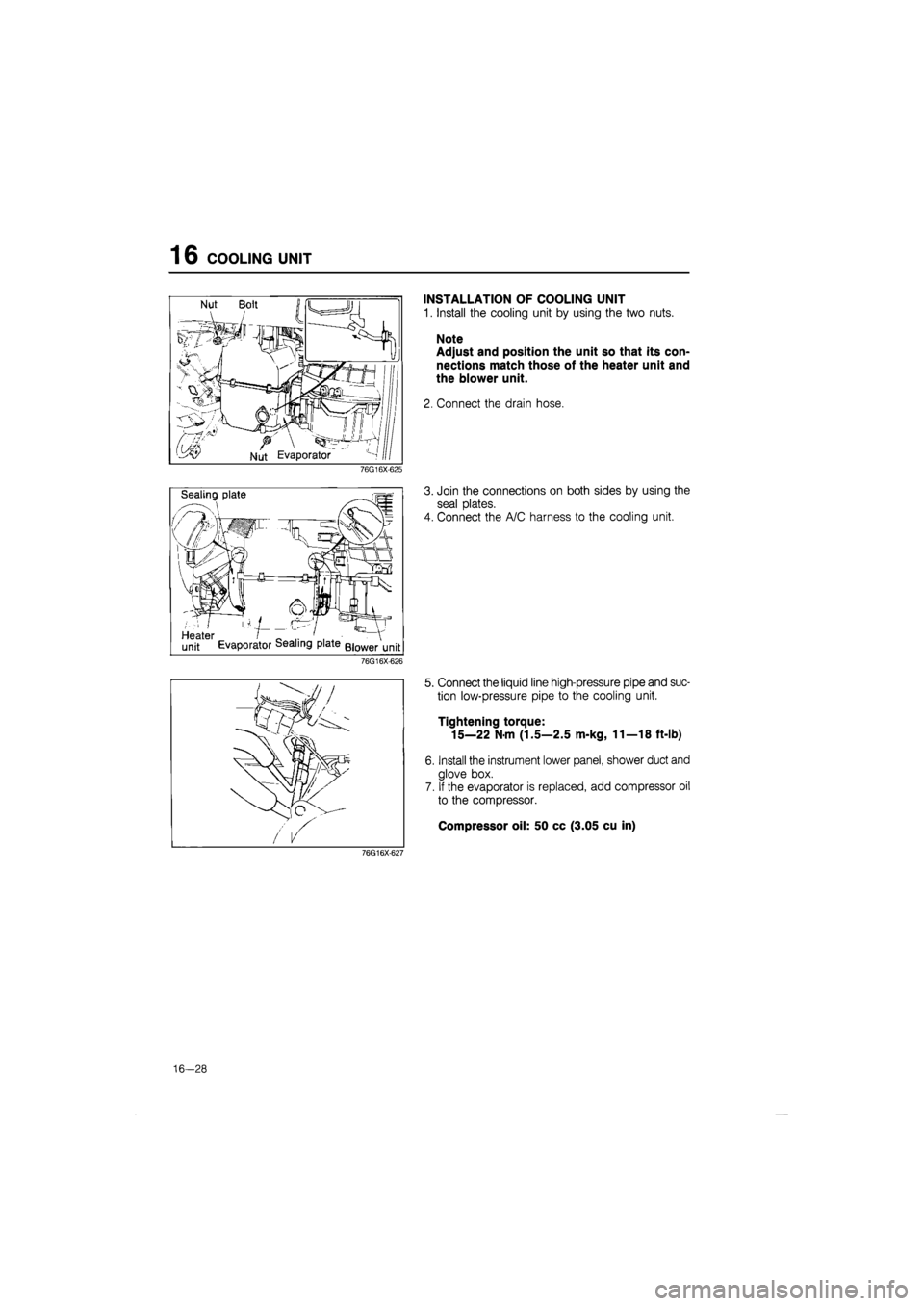
INSTALLATION OF COOLING UNIT
1. Install the cooling unit by using the two nuts.
Note
Adjust and position the unit so that its con-
nections match those of the heater unit and
the blower unit.
2. Connect the drain hose.
76G16X-625
Sealing plate
Heater I _ .. ' . . - V
unit Evaporator dealing plate Blower unit
3. Join the connections on both sides by using the
seal plates.
4. Connect the A/C harness to the cooling unit.
76G16X-626
76G16X-627
5. Connect the liquid line high-pressure pipe and suc-
tion low-pressure pipe to the cooling unit.
Tightening torque:
15—22 Nm (1.5—2.5 m-kg, 11—18 ft-lb)
6. Install the instrument lower panel, shower duct and
glove box.
7. If the evaporator is replaced, add compressor oil
to the compressor.
Compressor oil: 50 cc (3.05 cu in)
16-28
Page 1812 of 1865
REFRIGERANT LINES 1 6
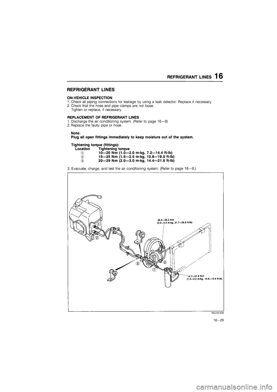
REFRIGERANT LINES
ON-VEHICLE INSPECTION
1. Check all piping connections for leakage by using a leak detector. Replace if necessary.
2. Check that the hose and pipe clamps are not loose.
Tighten or replace, if necessary.
REPLACEMENT OF REFRIGERANT LINES
1. Discharge the air conditioning system. (Refer to page 16—9)
2. Replace the faulty pipe or hose.
Note:
Plug all open fittings immediately to keep moisture out of the system.
Tightening torque (fittings):
Location Tightening torque
© 10—20 N m (1.0—2.0 m-kg, 7.2—14.4 ft-lb)
© 15—25 Nm (1.5—2.5 m-kg, 10.8—18.0 ft-lb)
© 20—29 Nm (2.0—3.0 m-kg, 14.4—21.6 ft-lb)
3. Evacuate, charge, and test the air conditioning system. (Refer to page 16—9.)
76G16X-628
16—29
Page 1815 of 1865
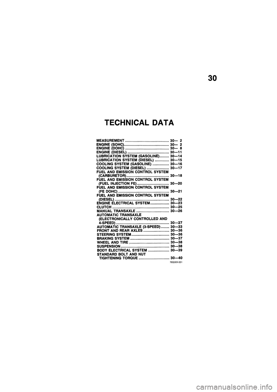
30
TECHNICAL DATA
MEASUREMENT 30— 2
ENGINE (SOHC) 30— 2
ENGINE (DOHC) 30— 8
ENGINE (DIESEL) 30—11
LUBRICATION SYSTEM (GASOLINE) 30—14
LUBRICATION SYSTEM (DIESEL) 30—15
COOLING SYSTEM (GASOLINE) 30—16
COOLING SYSTEM (DIESEL) 30—17
FUEL AND EMISSION CONTROL SYSTEM
(CARBURETOR) 30—18
FUEL AND EMISSION CONTROL SYSTEM
(FUEL INJECTION FE) 30—20
FUEL AND EMISSION CONTROL SYSTEM
(FE DOHC) 30—21
FUEL AND EMISSION CONTROL SYSTEM
(DIESEL) 30—22
ENGINE ELECTRICAL SYSTEM 30—23
CLUTCH 30—25
MANUAL TRANSAXLE 30—26
AUTOMATIC TRANSAXLE
(ELECTRONICALLY CONTROLLED AND
4-SPEED) 30—27
AUTOMATIC TRANSAXLE (3-SPEED) 30—33
FRONT AND REAR AXLES 30—36
STEERING SYSTEM 30—36
BRAKING SYSTEM 30—37
WHEEL AND TIRE 30—38
SUSPENSION 30—38
BODY ELECTRICAL SYSTEM 30—39
STANDARD BOLT AND NUT
TIGHTENING TORQUE 30—40
76G30X-001
Page 1843 of 1865
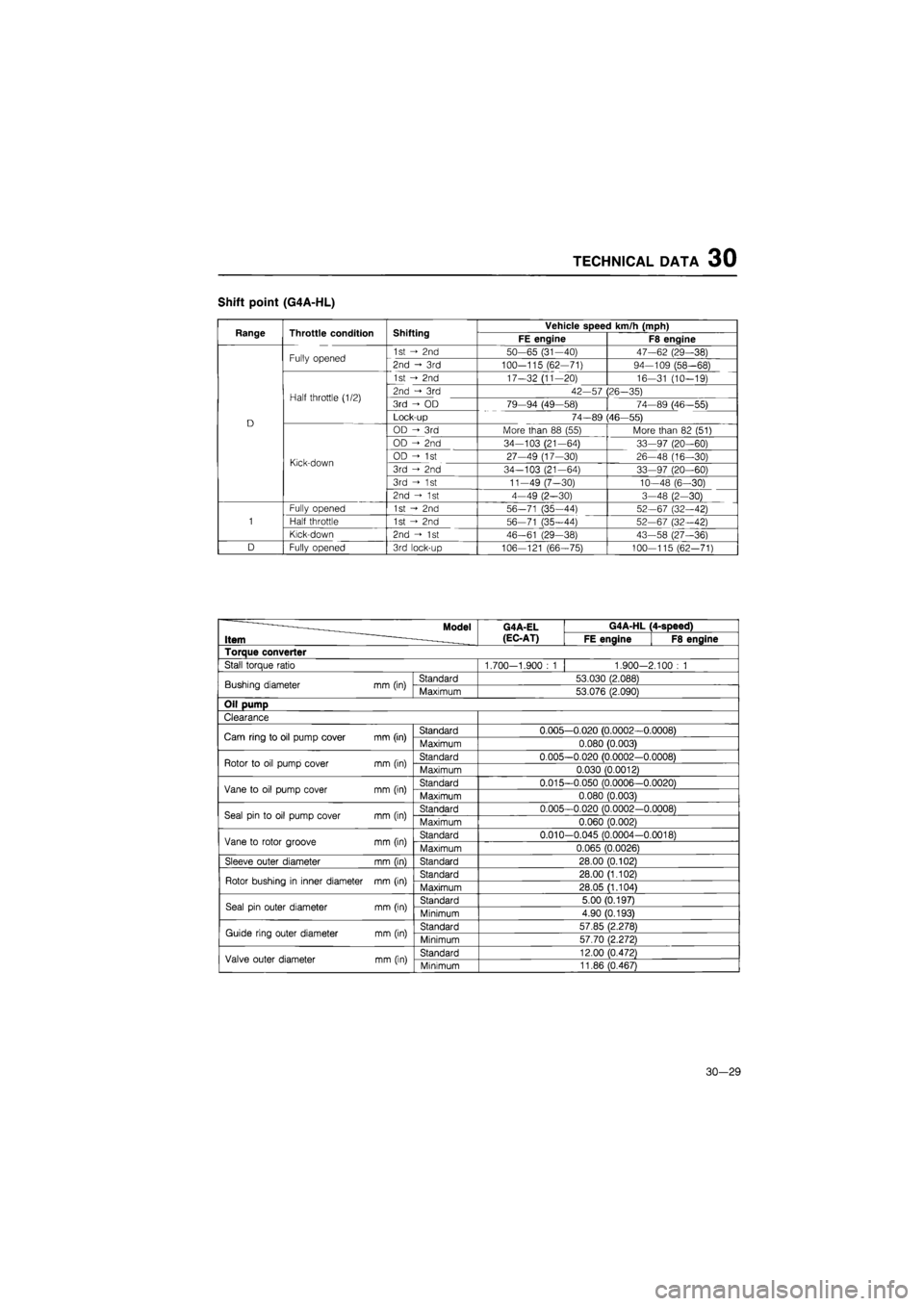
TECHNICAL DATA 30
Shift point (G4A-HL)
Range Throttle condition Shifting Vehicle speed km/h (mph) Range Throttle condition Shifting FE engine F8 engine
Fully opened 1st -> 2nd 50-65 (31-40) 47-62 (29—38) Fully opened 2nd ->• 3rd 100-115 (62-71) 94-109 (58-68)
1st 2nd 17-32 (11-20) 16-31 (10-19)
Half throttle (1/2) 2nd 3rd 42-57 (26-35) Half throttle (1/2) 3rd - OD 79-94 (49-58) 74—89 (46—55)
D Lock-up 74-89 (46—55) D OD - 3rd More than 88 (55) More than 82 (51)
OD -> 2nd 34-103 (21-64) 33-97 (20-60)
Kick-down OD - 1st 27-49 (17-30) 26-48 (16—30) Kick-down 3rd - 2nd 34-103 (21-64) 33-97 (20—60)
3rd ->• 1st 11-49 (7-30) 10—48 (6-30)
2nd -> 1st 4-49 (2-30) 3-48 (2-30)
Fully opened 1st 2nd 56-71 (35—44) 52-67 (32-42)
1 Half throttle 1st -> 2nd 56-71 (35-44) 52-67 (32—42)
Kick-down 2nd - 1st 46-61 (29-38) 43-58 (27-36)
D Fully opened 3rd lock-up 106-121 (66-75) 100—115 (62-71)
—___ Model
Item -
G4A-EL
(EC-AT)
G4A-HL (4-speed) —___ Model
Item -
G4A-EL
(EC-AT) FE engine F8 engine
Torque converter
Stall torque ratio 1.700-1.900
: 1
1.900-2.100
: 1
Bushing diameter
mm
(in) Standard 53.030 (2.088) Bushing diameter
mm
(in) Maximum 53.076 (2.090)
Oil pump
Clearance
Cam ring
to
oil pump cover mm (in) Standard 0.005—0.020 (0.0002—0.0008) Cam ring
to
oil pump cover mm (in) Maximum 0.080 (0.003)
Rotor
to oil
pump cover
mm
(in) Standard 0.005-0.020 (0.0002-0.0008) Rotor
to oil
pump cover
mm
(in) Maximum 0.030 (0.0012)
Vane
to oil
pump cover mm (in) Standard 0.015—0.050 (0.0006—0.0020) Vane
to oil
pump cover mm (in) Maximum 0.080 (0.003)
Seal pin
to oil
pump cover
mm
(in) Standard 0.005-0.020 (0.0002-0.0008) Seal pin
to oil
pump cover
mm
(in) Maximum 0.060 (0.002)
Vane
to
rotor groove
mm
(in) Standard 0.010-0.045 (0.0004-0.0018) Vane
to
rotor groove
mm
(in) Maximum 0.065 (0.0026)
Sleeve outer diameter
mm
(in) Standard 28.00 (0.102)
Rotor bushing
in
inner diameter
mm
(in) Standard 28.00 (1.102) Rotor bushing
in
inner diameter
mm
(in) Maximum 28.05 (1.104)
Seal pin outer diameter mm (in) Standard 5.00(0.197) Seal pin outer diameter mm (in) Minimum 4.90 (0.193)
Guide ring outer diameter
mm
(in) Standard 57.85 (2.278) Guide ring outer diameter
mm
(in) Minimum 57.70 (2.272)
Valve outer diameter
mm
(in) Standard 12.00 (0.472) Valve outer diameter
mm
(in) Minimum 11.86 (0.467)
30—29
Page 1846 of 1865
30 TECHNICAL DATA
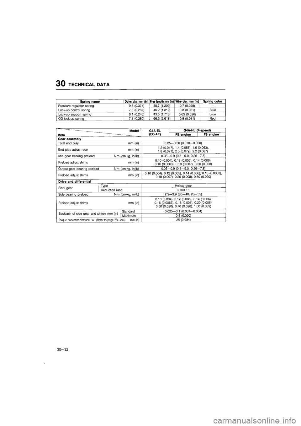
Spring name Outer dia. mm (in) Free length mm (in) Wire dia. mm (in)
I
Spring color
Pressure regulator spring 9.5 (0.374) 30.7 (1.209) 0.7 (0.028)
—
Lock-up control spring 7.3 (0.287) 46.2 (1.819) 0.8 (0.031) Blue
Lock-up support spring 6.1 (0.240) 43.5 (1.713) 0.65 (0.026) Blue
OD lock-up spring 7.1 (0.280) 66.5 (2.618) 0.8 (0.031) Red
Model G4A-EL G4A-HL 4-speed)
Item (EC-AT) FE engine F8 engine
Gear assembly
Total end play mm (in) 0.25-0.50 (0.010-0.020)
End play adjust race mm (in) 1.2 (0.047),
1.4
(0.055),
1.6
(0.063),
1.8 (0.071), 2.0 (0.079),
2.2
(0.087)
Idle gear bearing preload N
m
(cm-kg, in-lb) 0.03--0.9 (0.3—9.0, 0.26 -7.8)
Preload adjust shims mm (in) 0.10 (0.004), 0.12 (0.005), 0.14 (0.006), 0.16 (0.0063), 0.18 (0.007), 0.20 (0.008)
Output gear bearing preload N-m (cm-kg, in-lb) 0.03--0.9 (0.3—9.0, 0.26 -7.8)
Preload adjust shims mm (in) 0.10 (0.004), 0.12 (0.005), 0.14 (0.006), 0.16 (0.0063),
0.18 (0.007), 0.20 (0.008), 0.50 (0.020)
Drive and differential
Final gear Type Helical gear Final gear Reduction ratio 3,700
: 1
Side bearing preload N-m (cm-kg, in-lb) 2.9 —3.9 (30-40,
26-
35)
Preload adjust shims mm (in)
0.10 (0.004), 0.12 (0.005), 0.14 (0.006), 0.16 (0.0063), 0.18 (0.007), 0.20 (0.008), 0.50 (0.020), 0.70 (0.028), 1.00 (0.039)
Backlash
of
side gear and pinion
mm (in)
Standard 0.025-0.1 (0.001-0.004) Backlash
of
side gear and pinion
mm (in)
Maximum 0.5 (0.020)
Torque converter distance "A" (Refer to page 7B— 214) mm (in) 25 (0.984)
30-32
Page 1847 of 1865
TECHNICAL DATA 30
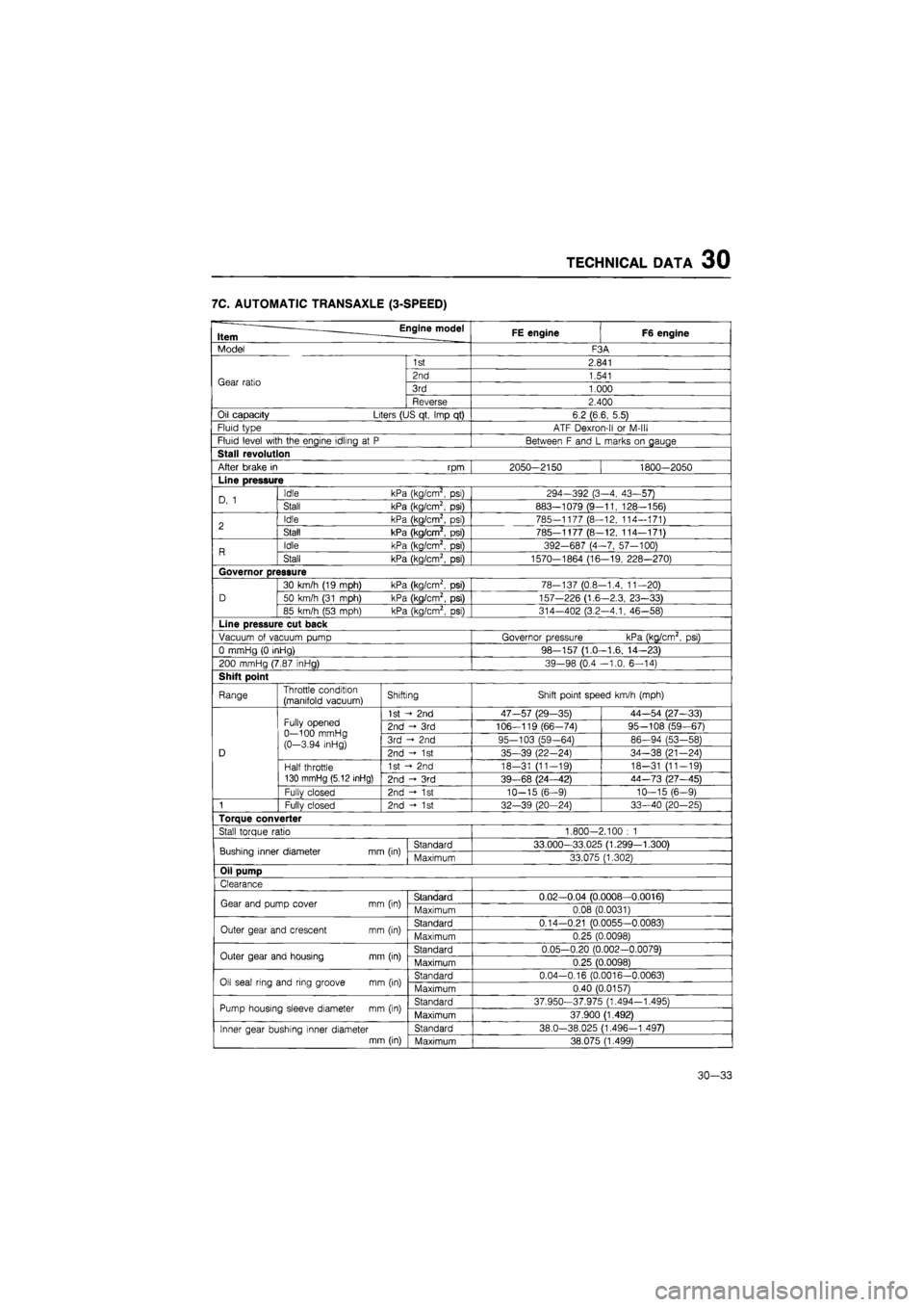
7C. AUTOMATIC TRANSAXLE (3-SPEED)
Engine model Item FE engine F6 engine
Model F3A
Gear ratio
1st 2.841
Gear ratio 2nd 1.541 Gear ratio 3rd 1.000 Gear ratio
Reverse 2.400
Oil capacity Liters (US qt, Imp
qt)
6.2 (6.6, 5.5)
Fluid type ATF Dexron-ll
or
M-lll
Fluid level with the engine idling
at P
Between
F
and
L
marks
on
gauge
Stall revolution
After brake
in rpm
2050-2150 1800—2050
Line pressure
D,
1
Idle kPa (kg/cm2,
psi)
294-392 (3-4, 43-57) D,
1
Stall kPa (kg/cm2,
psi)
883—1079 (9-11, 128-156)
2 Idle kPa (kg/cm2,
psi)
785-1177 (8—12, 114-171) 2 Stall kPa (kg/cm2,
psi)
785-1177 (8-12, 114—171)
R Idle kPa (kg/cm2,
psi)
392-687 (4-7, 57-100) R Stall kPa (kg/cm2,
psi)
1570-1864 (16-19, 228—270)
Governor pressure
D
30 km/h (19 mph) kPa (kg/cm2,
psi)
78-137 (0.8-1.4, 11-20)
D 50 km/h (31 mph) kPa (kg/cm2, psi) 157-226 (1.6-2.3, 23-33) D
85 km/h
(53
mph) kPa (kg/cm2,
psi)
314-402 (3.2—4.1, 46—58)
Line pressure cut back
Vacuum
of
vacuum pump Governor pressure kPa (kg/cm2,
psi)
0 mmHg
(0
inHg) 98-157 (1.0—1.6, 14—23)
200 mmHg (7.87 inHg) 39-98 (0.4 -1.0, 6-14)
Shift point
Range Throttle condition (manifold vacuum) Shifting Shift point speed km/h (mph)
D
Fully opened 0—100 mmHg (0-3.94 inHg)
1st
- 2nd
47-57 (29-35) 44—54 (27—33)
D
Fully opened 0—100 mmHg (0-3.94 inHg)
2nd
- 3rd
106—119 (66-74) 95—108 (59—67)
D
Fully opened 0—100 mmHg (0-3.94 inHg) 3rd
2nd
95-103 (59-64) 86—94 (53-58)
D
Fully opened 0—100 mmHg (0-3.94 inHg) 2nd -<•
1st
35-39 (22-24) 34-38 (21—24) D
Half throttle 130 mmHg (5.12 inHg)
1st
- 2nd
18-31 (11-19) 18-31 (11-19)
D
Half throttle 130 mmHg (5.12 inHg) 2nd
- 3rd
39-68 (24—42) 44-73 (27—45)
D
Fullv closed 2nd
- 1st
10-15 (6-9) 10—15 (6—9)
1 Fully closed 2nd -»•
1st
32—39 (20—24) 33—40 (20—25)
Torque converter
Stall torque ratio 1.800-2.100
: 1
Bushing inner diameter mm (in) Standard 33.000—33.025 (1.299—1.300) Bushing inner diameter mm (in) Maximum 33.075 (1.302)
Oil pump
Clearance
Gear and pump cover
mm
(in) Standard 0.02—0.04 (0.0008—0.0016) Gear and pump cover
mm
(in) Maximum 0.08 (0.0031)
Outer gear and crescent
mm
(in) Standard 0.14-0.21 (0.0055-0.0083) Outer gear and crescent
mm
(in) Maximum 0.25 (0.0098)
Outer gear and housing
mm
(in) Standard 0.05-0.20 (0.002-0.0079) Outer gear and housing
mm
(in) Maximum 0.25 (0.0098)
Oil seal ring and ring groove
mm
(in) Standard 0.04-0.16 (0.0016-0.0063) Oil seal ring and ring groove
mm
(in) Maximum 0.40 (0.0157)
Pump housing sleeve diameter
mm
(in) Standard 37.950-37.975 (1.494-1.495) Pump housing sleeve diameter
mm
(in) Maximum 37.900 (1.492)
Inner gear bushing inner diameter mm (in)
Standard 38.0-38.025 (1.496—1.497) Inner gear bushing inner diameter mm (in) Maximum 38.075 (1.499)
30—33