Page 612 of 1865

FUEL SYSTEM
4C
TROUBLESHOOTING
Checking the condition of the wiring harness and connectors before checking the sensors or switches.
Note
If
no
problem
is
found, continue with inspection
of the
next system
of
Troubleshooting
Guide. (Refer
to
page 4C—10,
and 11)
Possible cause 0 CO £ O ** CO £ O "5
Page
o CO c 0> (A
S o c
w O M C
.fc <0 "o
^ o w c 0) <0 c « o>
Im O CO c w w
0>
!
41 10 o E k 0) £ **
d>
5 <0 O E ^ 0) £
w 0
Fuel
pump
Injector Fuel
pressure
Engine control
unit terminal
a. E 3 a
a> » c
Transfer
pump
sv
(4WS)
ha c o o
if Qj
«> S£
< g. X O £ 1-ID a 5
Fuel
pump
Injector Fuel
pressure
1Q 3C,3E 3F,3H 3B ID k_ H
Transfer
pump
sv
(4WS) 3
C
U.
3
Symptom *C—103 4C—110 4C—107 4C—104 4C—107 4C—106 4C-56 4C-57 4C-54 4C-98 40-59
Hard start
or
won't start (Cranks
OK)
— — —-— g — 1 7 — 2 8 6 3 4 5
Engine During warm
up
4 — — — 3 — — 2 1 — 5 — — — —
stalls After warm
up
1 — — — — — — 3 2 — 4 — — — —
Rough During warm
up
5 — — — 3 — — 2 1 — 4 — — — —
a> 3 Idle After warm
up
1 6 — — 4 — — 3 2 — 5 — — — —
•o a> •o (0 a> c -»
Poor acceleration, hesi-tation,
or
lack
of
power 1 — — 3 5 — — 4 2 — 6 — — — — •o a> •o (0 a> c -» Runs
rough on
deceleration 1 — — — — — — 2 — — 3 — — — —
Afterburn on deceleration 1 — — — — — — 2 — — 3 — — — —
Poor fuel consumption 6 — 5 — 4 — — 2 1 — 3 — — — —
Engine stalls
or
runs rough after hot starting 1 5 — — — — — 3 2 — 4 — — — —
Falls emission test — — 1 — — 2 — 3 — — 4 — — — —
Hard start
or
won't
start (Cranks
OK)
— — — — 9 — 1 7 — 2 8 6 3 4 5
Engine During warm
up
4 — — — 3 — — 2 1 — 5 — — — —
stalls After warm
up
1 — — — — — — 3 2 — 4 — — — —
Rough During warm
up
— — — 3 — — 2 1 — 4 — — — —
a> 3 Idle After warm
up
1 6 — — 4 — — 3 2 — 5 — — — —
•o a> •o a
Poor acceleration, hesi-tation,
or
lack
of
power 1 — — — 4 — — 3 2 — 5 — — — —
a> Runs rough on deceleration 1 — — — — — — 2 — — 3 — — — —
Afterburn on deceleration 1 — — — — — — 2 — — 3 — — — —
Poor fuel consumption 5 — — — 4 — — 2 1 — 3 — — — —
Engine stalls
or
runs rough after
hot
staring 1 5 — — — — — 3 2 — 4 — — — —
Falls emission test 1 ?
76G04C-089
4C—51
Page 613 of 1865
4C FUEL SYSTEM
FUEL PRESSURE RELEASE AND SERVICING
FUEL SYSTEM
Fuel in the fuel system remains under high pressure
even when the engine is not running.
a) Before disconnecting any fuel line, release the fuel
pressure from the fuel system to reduce the pos-
sibility of injury or fire.
1. Start the engine.
2. Disconnect the 4-pin connector from the con-
trol relay or the fuel pump connector (5-pin or
6-pin).
3. After the engine stalls, turn OFF the ignition
switch.
4. Reconnect the relay or fuel pump connector.
b) Use a rag as protection from fuel spray when dis-
connecting the hoses.
Plug the hoses after removal.
c) When inspecting the fuel system, use the SST.
4C—52
Page 615 of 1865

4C FUEL SYSTEM
f-|To pulsation
-'damper
76G04C-092
Pressure regulator
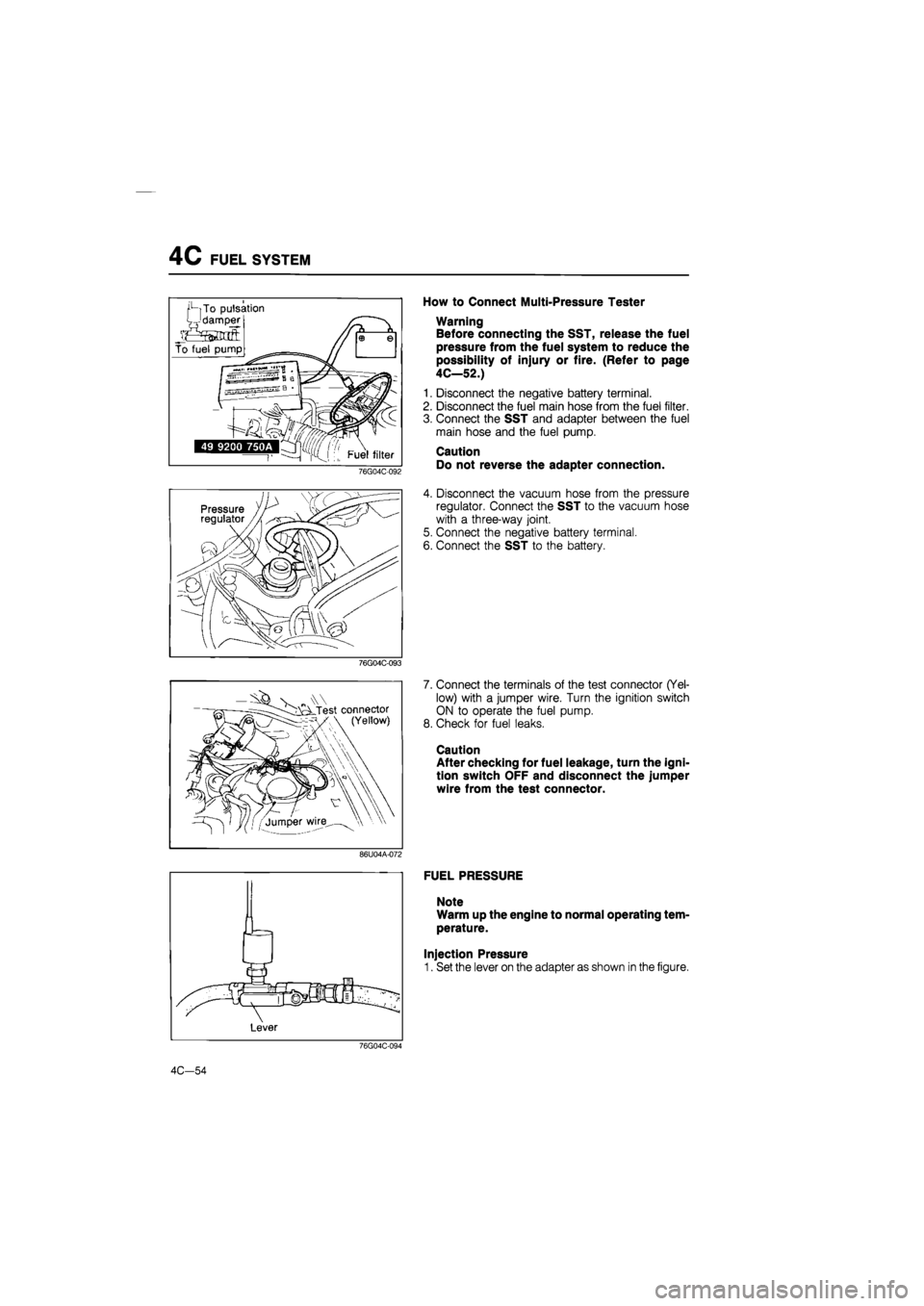
How to Connect Multi-Pressure Tester
Warning
Before connecting the SST, release the fuel
pressure from the fuel system to reduce the
possibility of injury or fire. (Refer to page
4C—52.)
1. Disconnect the negative battery terminal.
2. Disconnect the fuel main hose from the fuel filter.
3. Connect the SST and adapter between the fuel
main hose and the fuel pump.
Caution
Do not reverse the adapter connection.
4. Disconnect the vacuum hose from the pressure
regulator. Connect the SST to the vacuum hose
with a three-way joint.
5. Connect the negative battery terminal.
6. Connect the SST to the battery.
76G04C-093
V „ Test connector (Yellow)
7. Connect the terminals of the test connector (Yel-
low) with a jumper wire. Turn the ignition switch
ON to operate the fuel pump.
8. Check for fuel leaks.
Caution
After checking for fuel leakage, turn the igni-
tion switch OFF and disconnect the jumper
wire from the test connector.
86U04A-072
FUEL PRESSURE
Note
Warm up the engine to normal operating tem-
perature.
Injection Pressure
1. Set the lever on the adapter as shown in the figure.
76G04C-094
4C-54
Page 616 of 1865

FUEL SYSTEM 4C
i i 1 1 1 i i
r.:.:::r t t t t t izn —i—i—i—i—i—i—i—i—
2DD 350
86U04A-074
2. Run the engine and measure the injection pres-
sure at various speeds.
Injection pressure: Approx. 235—275 kPa
(2.4—2.8 kg/cm2, 34—40 psi)
3. If not within specification, check the fuel pump pres-
sure and fuel line pressure.
Fuel Pump Pressure
1. Connect the terminals of the test connector (Yel-
low) with a jumper wire.
2. Turn the ignition switch ON to operate the fuel
pump.
3. Set the lever on the adapter as shown in the figure.
4. Check the fuel pump pressure.
Fuel pump pressure: 441—588 kPa
(4.5—6.0 kg/cm2, 64—85 psi)
5. If the fuel pump pressure is not within specifica-
tion, check the following;
No pressure
• Fuel pump operation (Refer to page
4C—56.)
Low pressure
• Fuel pump feeding capacity (Refer to
page 4C—56.)
High pressure
• Replace the fuel pump
6. After checking the fuel pump pressure, disconnect
the jumper wire from the test connector.
Fuel Line Pressure
1. Start the engine and run it idle.
2. Set the lever on the adapter as shown in the figure.
3. Check the fuel line pressure.
Fuel line pressure: Approx. 186—226 kPa
(1.9—2.3 kg/cm2, 27—33 psi)
4. If not within specification, check the pressure regu-
lator vacuum hose.
4C-55
Page 618 of 1865
FUEL SYSTEM 4C
Pulsation damper
76G04C-100
Intake mainfold
3. Turn the ignition switch ON for 10 seconds, and
check the feeding capacity with graduated
cylinder.
Feeding capacity:
Minimum 220 cc (13.4 cu in)/10 sec.
4. If not within specification, check the fuel filter, fuel
lines and fuel pump.
5. Turn the ignition switch OFF and disconnect the
jumper wire.
PULSATION DAMPER
1. Run the engine at idle.
2. Place a finger on the screw of the pulsation damper
head.
3. Check that pulsation is felt.
86U04A-083
Injector
INJECTOR
On-vehicle Inspection
1. Warm up the engine and run it at idle.
2. Listen for operational sound of the injector with a
screwdriver or a sound scope.
76G04C-101
3. Ground the test connector (Green, 1-pin).
76G04C-102
4C-57
Page 619 of 1865

4C FUEL SYSTEM
76G04C-103
76G04C-104
76G04C-105
- s A Test connector I \ (Yellow)
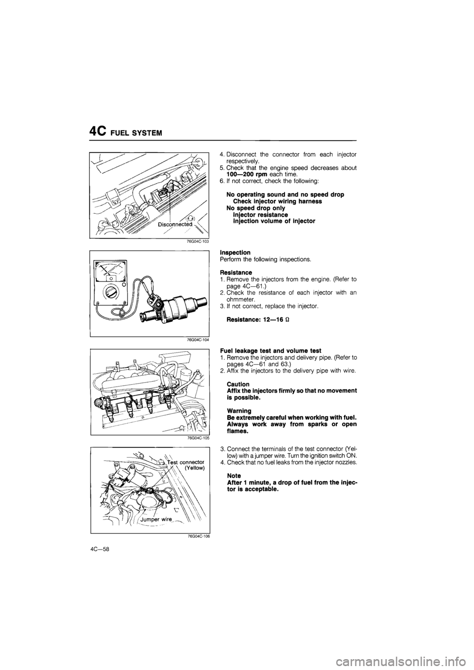
4. Disconnect the connector from each injector
respectively.
5. Check that the engine speed decreases about
100—200 rpm each time.
6. If not correct, check the following:
No operating sound and no speed drop
Check injector wiring harness
No speed drop only
Injector resistance
Injection volume of injector
Inspection
Perform the following inspections.
Resistance
1. Remove the injectors from the engine. (Refer to
page 4C—61.)
2. Check the resistance of each injector with an
ohmmeter.
3. If not correct, replace the injector.
Resistance: 12—16 Q
Fuel leakage test and volume test
1. Remove the injectors and delivery pipe. (Refer to
pages 4C—61 and 63.)
2. Affix the injectors to the delivery pipe with wire.
Caution
Affix the injectors firmly so that no movement
is possible.
Warning
Be extremely careful when working with fuel.
Always work away from sparks or open
flames.
3. Connect the terminals of the test connector (Yel-
low) with a jumper wire. Turn the ignition switch ON.
4. Check that no fuel leaks from the injector nozzles.
Note
After 1 minute, a drop of fuel from the injec-
tor is acceptable.
76G04C-106
4C—58
Page 622 of 1865
FUEL SYSTEM 4C
76G04C-112
86U04B-083
76G04C-113
Transfer Pump
1. Remove the fuel tank. (Refer to page 4C—65.)
2. Disconnect the fuel hoses from the transfer pump.
3. Remove the transfer pump.
4. Install in the reverse order of removal.
Injector
1. Remove the engine hanger.
2. Remove the wiring harness bracket.
3. Disconnect the PCV valve and hose from the dy-
namic chamber.
76G04C-114
4C-61
Page 623 of 1865
4C FUEL SYSTEM
4. Disconnect the main fuel hose from the delivery
pipe assembly.
5. Disconnect the fuel return hose from the fuel re-
turn pipe.
6. Remove fuel return pipe mounting bolt.
76G04C-115
7. Remove the delivery pipe assembly mounting bolts
and insulators.
76G04C-116
Remove the grommets, injectors, and insulators.
Install in the reverse order of removal, referring to
the installation note.
Tightening torque:
Delivery pipe, dynamic chamber, and en-
gine hanger
19—25 N m (1.9—2.6 m-kg, 14—19 ft-lb)
76G04C-117
O-ring Injector / Correct
v L
Grommet Delivery pipe
Wrong
/
Dc^Li Wrong
Installation note
Injector
1. Use new O-rings.
2. Apply a small amount of engine oil to the O-rings
when installing.
86U04A-108
4C-62