Page 1568 of 1865
FRONT DOORS 1 4
86U14X-042
86U14X-043
69G14X-038
2. Remove the key cylinder spring.
3. Remove the key cylinder.
4. Remove the mounting nuts and remove the outer
handle.
Removal of Door Lock Assembly
1. Remove the mounting screws.
2. Remove the door lock assembly.
INSTALLATION
Install in the reverse order of removal, noting the fol-
lowing.
Power Window
Before installing the motor, connect the leads to a bat-
tery and run the regulator down to the position shown.
63U14X-035
14—17
Page 1573 of 1865
1 4 REAR DOORS
Installation of door lock and outer handle
1. Before installing the door lock, apply grease to the
places shown in the figure.
2. After installation, check that the door opens
smoothly, and that the operation of the lock is cor-
rect when using the key and the door lock knob.
86U14X-054
ADJUSTMENT
Door Lock Striker
1. Check that the door can be closed easily and
whether there is any looseness. If there is a prob-
lem, loosen the striker mounting screws and ad-
just by moving the striker vertically, or laterally.
2. Check the rear offset of the door to the body. If
there is a problem, adjust by moving the door lock
striker laterally.
86U14X-055
14—22
Page 1665 of 1865
5
IGNITION
SWITCH
76G15X-026
B IG1
ST ST •S
Key reminder switch
~
Key reminder switch
ON
Lock
ACC
ACC
69G15X-014
REPLACEMENT
Disconnect the negative battery terminal. 30, 40 and
60A fuses: pull out and push in a new fuse.
80A fuse:
1. Remove the main fuse box.
2. Open the cover.
3. Remove the terminal.
4. Pull out and push in a new fuse.
IGNITION SWITCH
INSPECTION
1. Use an ohmmeter to check continuity of the termi-
nals of the switch.
2. If continuity is not as specified, replace the switch.
-^Terminal
Position"""-""---^^ B ACC IG2 IGi ST c d
LOCK Remove LOCK Insert 0--0
ACC O--0 O--0
ON O--O o--O o--o
ST r -O O--o ST -O O--o
): Indicates continuity
15—10
Page 1696 of 1865
CENTRAL PROCESSING UNIT (CPU) 1 5
CENTRAL PROCESSING UNIT (CPU)
STRUCTURAL VIEW
86U15X-071
FUNCTIONS
System Function
Sound Alarm System
Key reminder alarm
Sound Alarm System
Liaht-off reminder alarm
Sound Alarm System
Seat belt alarm
Timer System
Seat belt timer
Timer System
Kev illumination liaht timer
Timer System
Interior light timer
76G15X-008
15—41
Page 1697 of 1865
1 5 CENTRAL PROCESSING UNIT (CPU)
CIRCUIT DIAGRAM
-O-vO
I &
IG key
OFF
n\ Key reminder
Door ajar
warning light vf Door SW
llfl Engine control —_
unitj^"
Buckle SW
W7i
0
o
o
0
o
0
o
o
o
a
Q
u
n
dD
IG key
illumination light
[ Interior light
(f)
(f) (|)
teesy
J
cF Seat belt warning light
o o o 0 o o o
•a-
o o o o o o o
15-42
86U15X-073
Page 1698 of 1865

CENTRAL PROCESSING UNIT (CPU) 1 5
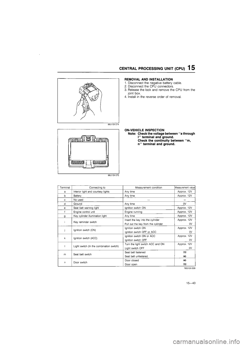
REMOVAL AND INSTALLATION
1. Disconnect the negative battery cable.
2. Disconnect the CPU connectors.
3. Release the lock and remove the CPU from the
joint box.
4. Install in the reverse order of removal.
ON-VEHICLE INSPECTION
Note: Check the voltage between "a through
I" terminal and ground.
Check the continuity between "m,
n" terminal and ground.
86U15X-075
Terminal Connecting
to
Measurement condition Measurement value
a Interior light and courtesy lights Any time Approx.
12V
b Batterv Anv time Approx.
12V
c No used
— —
d Ground Anv time OV
e Seat belt warning light Ignition switch
ON
Approx.
12V
f Enaine control unit Enaine runnina Approx.
12V
g Key cylinder illumination light Any time Approx.
12V
i Key reminder switch Insert the key into the cylinder
Pull out the key from the cylinder
Approx.
12V
OV
j Ignition switch (ON) Ignition switch
ON
Ignition switch OFF
or
ACC
Approx.
12V
OV
k Ignition switch (ACC) Ignition switch
ON or
ACC
Ignition switch OFF
Approx.
12V
OV
I Light switch (In the combination switch) Turn the light switch ACC and
ON
Light switch OFF
Approx.
12V
OV
m Seat belt switch Seat belt fastened
Seat belt unfastered
OQ
OO
n Door switch Door closed
Door open
OO
on
76G15X-009
15—43
Page 1769 of 1865
1 5 AUDIO SYSTEM
ADJUSTMENT (MTR)
Antenna adjustment
Use the following adjustment procedure to obtain op-
timum antenna and radio reception sensitivity.
1. Extend the antenna fully.
2. Set the ignition key to ACC.
3. Turn on the radio, and set it to AM reception.
4. Tune in a distant station with a weak signal at
around 1400 kHz. If such a station cannot be
found, use static to make the adjustment.
5. Turn the antenna trimmer adjustment screw to the
left and right to find the maximum sensitivity (of ei-
ther the broadcast or the static).
Note
If there is no change in the sensitivity, either
the tuned signal is too strong, or there is an
antenna malfunction or broken wire.
POWER ANTENNA
STRUCTURAL VIEW
1. Antenna motor
2. Antenna
FM M >08 ST ' I' tl -3-lx
0
[ AM s» TO too"I30"IM
J
A
FM | FM
B
I FH | fH
M FM
III
56G15X-106
15-114