Page 1423 of 1865

POWER BRAKE UNIT 1 1
76G11X-071
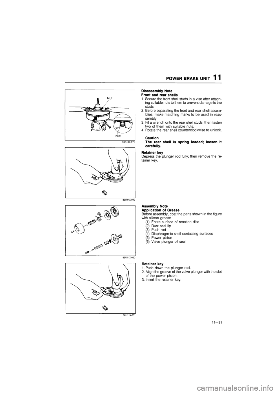
Disassembly Note
Front and rear shells
1. Secure the front shell studs in a vise after attach-
ing suitable nuts to them to prevent damage to the
studs.
2. Before separating the front and rear shell assem-
blies, make matching marks to be used in reas-
sembly.
3. Fit a wrench onto the rear shell studs; then fasten
two of them with suitable nuts.
4. Rotate the rear shell counterclockwise to unlock.
Caution
The rear shell is spring loaded; loosen it
carefully.
Retainer key
Depress the plunger rod fully; then remove the re-
tainer key.
86U11X-049
86U11X-050
Assembly Note
Application of Grease
Before assembly, coat the parts shown in the figure
with silicon grease.
(1) Entire surface of reaction disc
(2) Dust seal lip
(3) Push rod
(4) Diaphragm-to-shell contacting surfaces
(5) Power piston
(6) Valve plunger oil seal
Retainer key
1. Push down the plunger rod.
2. Align the groove of the valve plunger with the slot
of the power piston.
3. Insert the retainer key.
86U11X-051
11—31
Page 1556 of 1865
TRUNK LID 14
TRUNK
LID
STRUCTURAL VIEW (SEDAN AND COUPE/MX-6)
1. Trunk lid lock
2. Trunk lid opener protector
3. Opening rod
4. Retainer
5. Trunk lid key cylinder
6. Balance spring
76G14X-040
7. Trunk lid hinge bracket
8. Trunk lid hinge
9. Trunk lid
14—5
Page 1557 of 1865
1 4 TRUNK LID
86U14X-012
Opening rod
86U14X-013
86U14X-014
REMOVAL
Trunk Lid Opener
1. Remove the nut and the protector.
2. Remove the opening rod.
3. Remove the bolts and the trunk lid opener.
Trunk Lid Key Cylinder
Remove the retainer and the trunk lid key cylinder.
Trunk Lid
1. Remove the trunk lid installation bolts, then remove
the trunk lid.
2. Remove the balance spring.
3. Remove the rear seat. (Refer to page 14—100)
76G14X-041
14—6
Page 1560 of 1865
REAR HATCH 1 4
REAR HATCH
STRUCTURAL VIEW
86U14X-022
1. Rear hatch
2. Upper trim
3. Side trim
4. Lower trim
5. Rear finisher
6. Rear hatch lock
7. Lock controller
8. Rear hatch outer handle
9. Stay damper
10. Key cylinder
11. Rear hatch screen
14—9
Page 1562 of 1865
REAR HATCH 1 4
8. Remove the opening rod.
9. Remove the rear hatch opener.
86U14X-027
10. Remove the retainer, and the key cylinder.
86U14X-028
11. Remove the stay damper mounting bolts.
12. Disconnect the rear washer hose.
13. Remove the wiring harness.
86U14X-029
14. Remove the rear hatch hinge to door mounting
bolts.
15. Remove the rear hatch.
86U14X-030
14—11
Page 1564 of 1865
FRONT DOORS 1 4
FRONT DOORS
STRUCTURAL VIEW
86U14X-034
1. Power window switch
2. Regulator handle
3. Inner handle cover
4. Door trim
5. Door screen
6. Weatherstrip
7. Regulator (power type)
8. Regulator (manual type)
9. Key cylinder
10. Glass
11. Glass guide
12. Runchannel
13. Weatherstrip
14. Glass guide
15. Door checker
16. Door
17. Outer handle
18. Door mirror
19. Beltline molding
20. Weatherstrip
21. Sail inner garnish
14—13
Page 1565 of 1865
1 4 FRONT DOORS
1. Regulator handle
2. Arm rest
3. Power window switch
4. Inner handle cover
5. Door trim
6. Door screen
7. Weatherstrip
8. Regulator (power type)
9. Regulator (manual type)
10. Glass guide
11. Glass
12. Runchannel
13. Weatherstrip
14. Door
15. Door checker
16. Beltline molding
17. Weatherstrip
18. Door mirror
19. Outer handle
20. Key cylinder
21. Sail inner garnish
86U14X-035
14—14
Page 1567 of 1865
1 4 FRONT DOORS
86U14X-060
86U14X-040
86U14X-041
6. Remove the beltline molding. (Refer to page
14-39)
7. Remove the door glass upward.
8. Remove the mounting bolts, and remove the regu-
lator through the service hole.
9. Remove the window motor mounting bolt, and re-
move the motor from the regulator (power window).
Removal of Outer Handle and Key Cylinder
1. Disconnect the rod from the outer handle.
69G14X-036
14—16