1987 MAZDA 626 light
[x] Cancel search: lightPage 1740 of 1865
CRUISE CONTROL SYSTEM 1 5
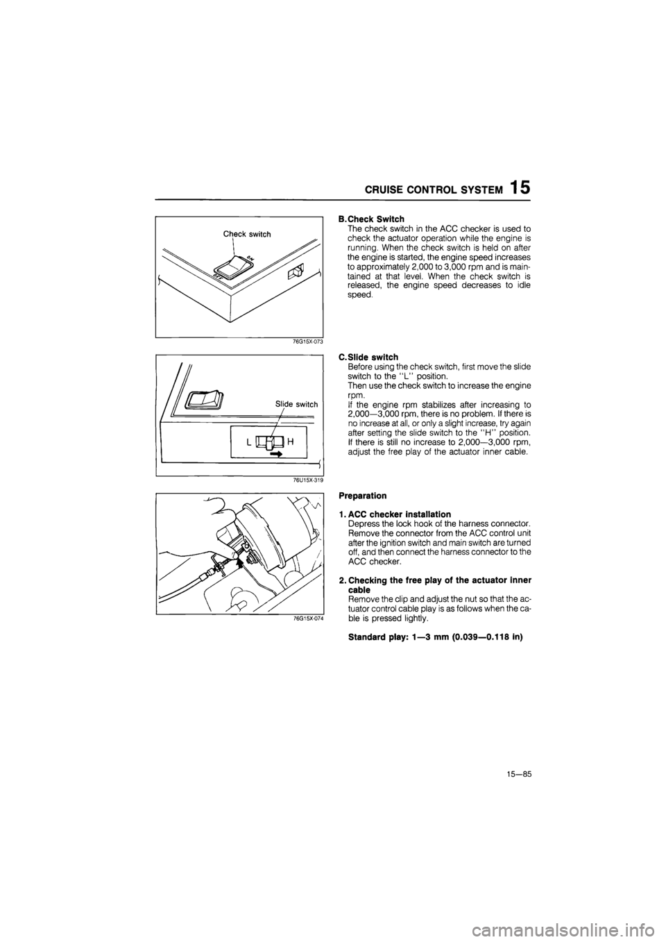
B.Check Switch
The check switch in the ACC checker is used to
check the actuator operation while the engine is
running. When the check switch is held on after
the engine is started, the engine speed increases
to approximately 2,000 to 3,000 rpm and is main-
tained at that level. When the check switch is
released, the engine speed decreases to idle
speed.
76G15X-073
C.Slide switch
Before using the check switch, first move the slide
switch to the "L" position.
Then use the check switch to increase the engine
rpm.
If the engine rpm stabilizes after increasing to
2,000—3,000 rpm, there is no problem. If there is
no increase at all, or only a slight increase, try again
after setting the slide switch to the "H" position.
If there is still no increase to 2,000—3,000 rpm,
adjust the free play of the actuator inner cable.
76U15X-319
76G15X-074
Preparation
1. ACC checker installation
Depress the lock hook of the harness connector.
Remove the connector from the ACC control unit
after the ignition switch and main switch are turned
off, and then connect the harness connector to the
ACC checker.
2. Checking the free play of the actuator inner
cable
Remove the clip and adjust the nut so that the ac-
tuator control cable play is as follows when the ca-
ble is pressed lightly.
Standard play: 1—3 mm (0.039—0.118 in)
15—85
Page 1741 of 1865
1
5
CRUISE CONTROL SYSTEM
Checking
the
System
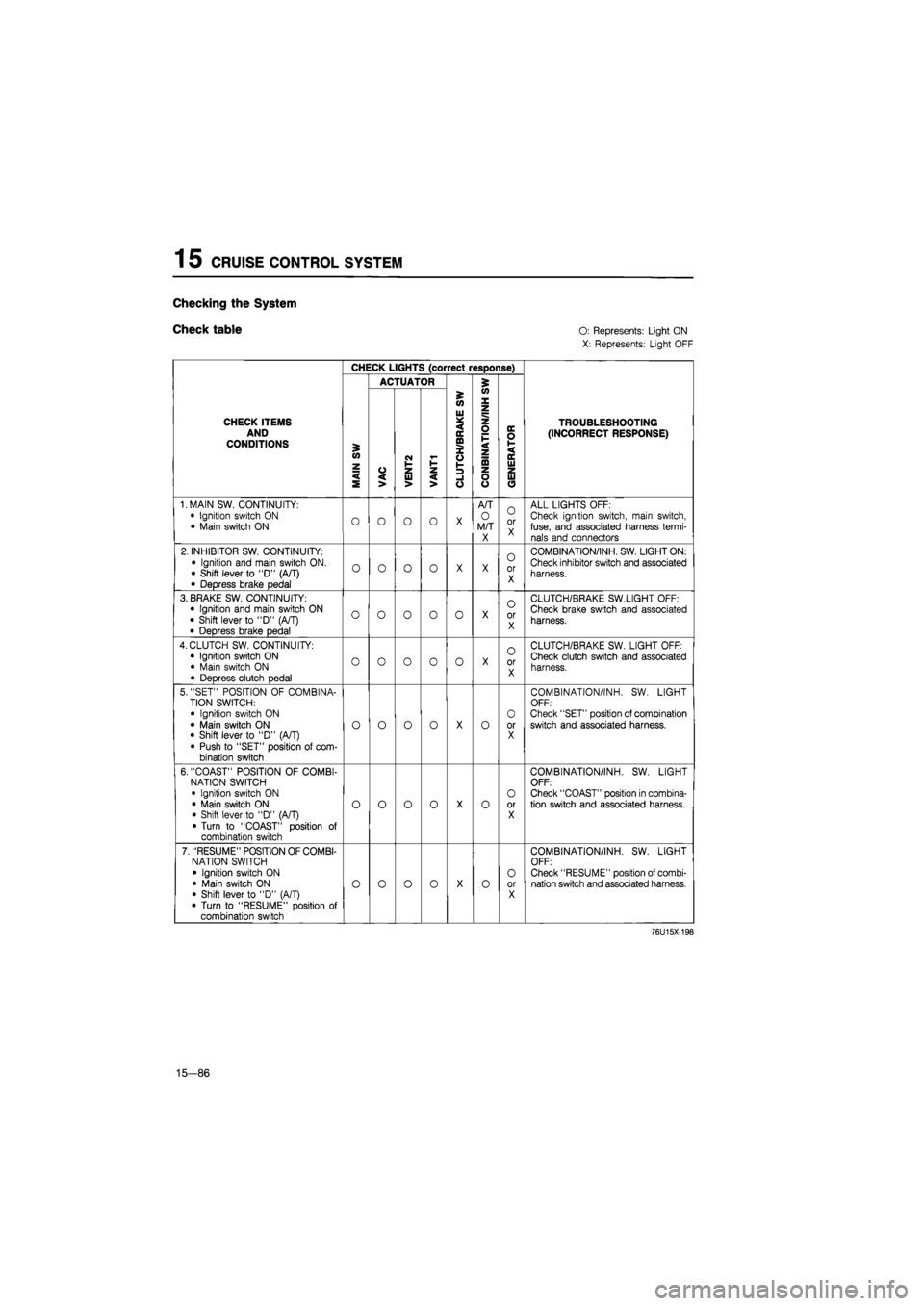
Check table O:
Represents: Light ON
X: Represents: Light OFF
CHECK LIGHTS (correct response)
ACTUATOR 5
CHECK ITEMS AND CONDITIONS
MAIN
SW
VAC
i
VENT2 VANT1
i
'
CLUTCH/BRAKE
SW
CONBINATION/INH
S
'
GENERATOR
TROUBLESHOOTING (INCORRECT RESPONSE)
1. MAIN SW. CONTINUITY:
• Ignition switch
ON
• Main switch
ON O O O o
X
A/T
O
M/T X
O
or X
ALL LIGHTS OFF: Check ignition switch, main switch, fuse, and associated harness termi-nals and connectors
2. INHIBITOR SW. CONTINUITY:
• Ignition and main switch ON. • Shift lever
to "D"
(A/T)
• Depress brake pedal
o o o o
X X
0
or X
COMBINATION/INH. SW. LIGHT ON:
Check inhibitor switch and associated
harness.
3. BRAKE SW. CONTINUITY: • Ignition and main switch
ON
• Shift lever
to
"D"
(A/T)
• Depress brake pedal
o o o o 0
X
o
or X
CLUTCH/BRAKE SW.LIGHT OFF:
Check brake switch and associated
harness.
4. CLUTCH SW. CONTINUITY:
• Ignition switch
ON
• Main switch
ON
• Depress clutch pedal
o o o 0 o
X
O
or X
CLUTCH/BRAKE SW. LIGHT OFF: Check clutch switch and associated harness.
5. "SET" POSITION
OF
COMBINA-TION SWITCH:
• Ignition switch
ON
• Main switch
ON
• Shift lever
to "D"
(A/T) • Push
to
"SET" position
of
com-bination switch
o o o o
X
o
O
or X
COMBINATION/INH.
SW.
LIGHT OFF: Check "SET" position of combination switch and associated harness.
6. "COAST" POSITION
OF
COMBI-NATION SWITCH • Ignition switch
ON
• Main switch
ON
• Shift lever
to "D"
(A/T) • Turn
to
"COAST" position
of
combination switch
o o o o
X
o
O
or X
COMBINATION/INH.
SW.
LIGHT OFF: Check "COAST" position in combina-tion switch and associated harness.
7. "RESUME" POSITION OF COMBI-NATION SWITCH
• Ignition switch
ON
• Main switch
ON
• Shift lever
to "D"
(A/T)
• Turn
to
"RESUME" position
of
combination switch
o o o o
X
o O
or X
COMBINATION/INH.
SW.
LIGHT OFF: Check "RESUME" position of combi-nation switch and associated harness.
76U15X-198
15—86
Page 1742 of 1865
CRUISE CONTROL SYSTEM 1 5
CHECK LIGHTS (correct response)
ACTUATOR £
5 (O
W X
CHECK ITEMS AND CONDITIONS £ <0 z
VAC
CM I-1-z
Ul * < IE ffl X o V-
z o F < z ta
DC O 1-< DC Ui
TROUBLESHOOTING
(INCORRECT RESPONSE)
< S VAC UJ > < > -1 o o o UJ O
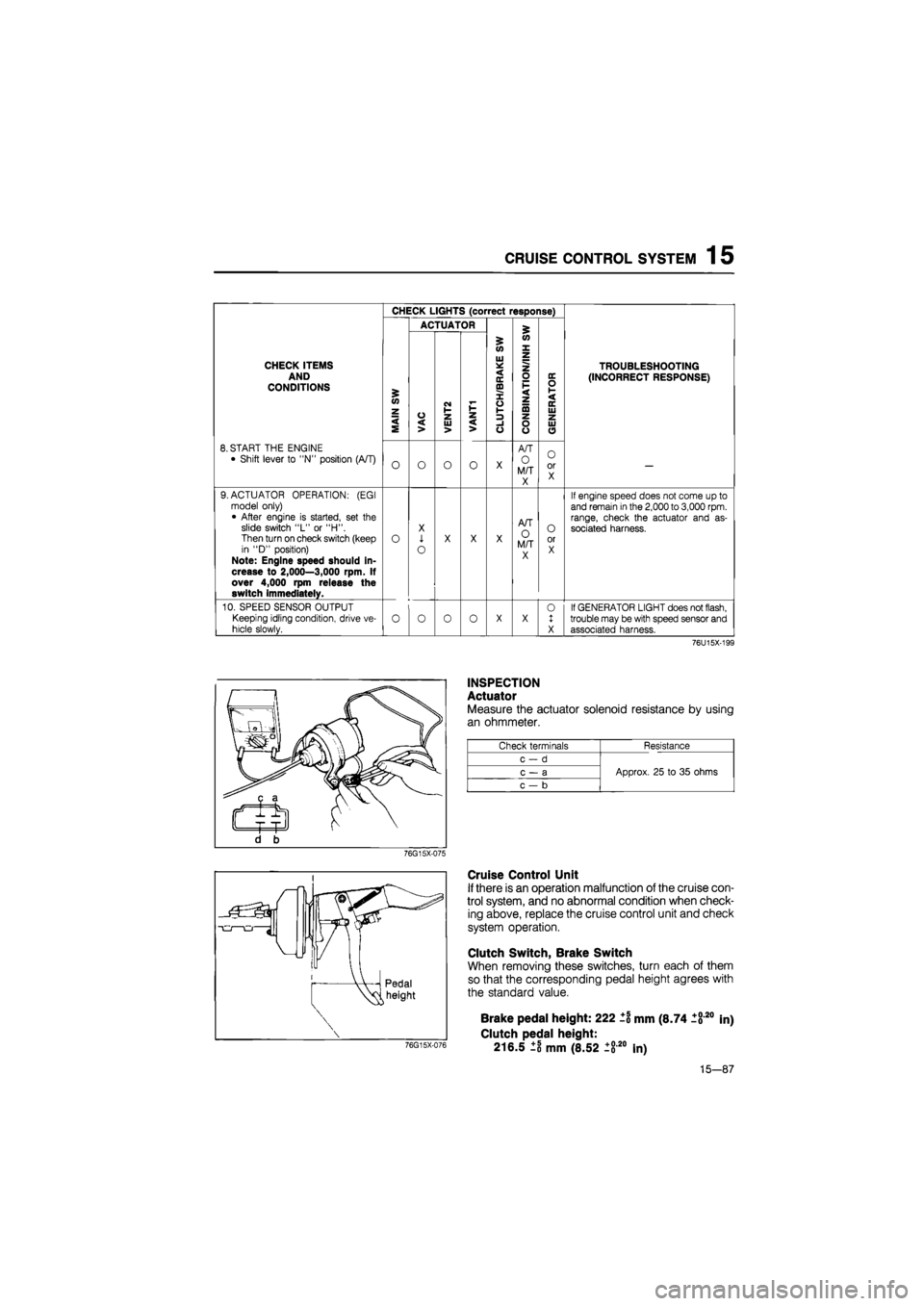
8. START THE ENGINE
• Shift lever to "N" position (A/T) O O O o X
A/T
O M/T X
O or X —
9. ACTUATOR OPERATION: (EGI model only) • After engine is started, set the slide switch "L" or "H". Then turn on check switch (keep in "D" position) Note: Engine speed should in-crease to 2,000—3,000 rpm. If over 4,000 rpm release the switch immediately.
o
X
1
o
X X X
A/T O M/T X
O or X
If engine speed does not come up to and remain
in
the
2,000
to
3,000
rpm. range, check the actuator and as-sociated harness.
10. SPEED SENSOR OUTPUT
Keeping idling condition, drive ve-
hicle slowly. o o 0 o X X 0 1 X
If GENERATOR LIGHT does not flash, trouble may be with speed sensor and associated harness.
76U15X-199
INSPECTION
Actuator
Measure the actuator solenoid resistance by using
an ohmmeter.
Check terminals Resistance
c-d
Approx. 25 to 35 ohms c — a Approx. 25 to 35 ohms
c — b
Approx. 25 to 35 ohms
76G15X-075
Cruise Control Unit
If there is an operation malfunction of the cruise con-
trol system, and no abnormal condition when check-
ing above, replace the cruise control unit and check
system operation.
Clutch Switch, Brake Switch
When removing these switches, turn each of them
so that the corresponding pedal height agrees with
the standard value.
76G15X-076
Brake pedal height: 222 ±1 mm (8.74 1820
Clutch pedal height:
216.5 ±8 mm (8.52 ±820 In)
in)
15-87
Page 1745 of 1865
![MAZDA 626 1987 Workshop Manual
1 5 SLIDING SUNROOF
CIRCUIT DIAGRAM
BATTEHY
© © P o-
B
[Fj -
80A
X-01
ff
WR [F] X-01 MAIN
X-06
FUSE
X-ffij
4 |
-WR [D]-
JB-09
©
Hit
LR
R|
LR [Fr) REAR HATCH
^T-06 T-06
MAZDA 626 1987 Workshop Manual
1 5 SLIDING SUNROOF
CIRCUIT DIAGRAM
BATTEHY
© © P o-
B
[Fj -
80A
X-01
ff
WR [F] X-01 MAIN
X-06
FUSE
X-ffij
4 |
-WR [D]-
JB-09
©
Hit
LR
R|
LR [Fr) REAR HATCH
^T-06 T-06](/manual-img/28/57059/w960_57059-1744.png)
1 5 SLIDING SUNROOF
CIRCUIT DIAGRAM
BATTEHY
© © P o-
B
[Fj -
80A
X-01
ff
WR [F] X-01 MAIN
X-06
FUSE
X-ffij
4 |
-WR [D]-
JB-09
©
Hit
LR
R|
LR [Fr) REAR HATCH
^T-06 T-06
BlFrj
Bl
i iii
-LR [In] -
15®
— JB-IO ® ROOM
^JB-03(
[
B[D| i
-J1
Unleaded Fuel (Except Sweden & West Germany)
X-D2
IGN SW
VX-OZ
BW |D|
r-oe T-01 JB-10 © 5SA@ ^JB-07®
= = = = = ^ T-05
BrW"|Frj RW IFi]
^ X-jfi
RW [R]
BrW'[H2| RW [R2|
LR
T-04
SUNROOF REUY No.1
I fp LW-' ly
4f - = - --
LW
S.G LY
REAR HATCH MOTOR
T-01 Connector Between Interior Light Harness [In] and Sunroof
T-02 Sunroof Sw
LG
LW G (±±±
B
l. LY
GO
LW LG ±±±
LY
L B
T-03 Sunroof Motor
Y
L LY YG
pL=LX Jh
TTTT1
YR
B
LG LW
YG
LY L Y
Ntttt) TTTT
LW LG
B YR
T-04 Sunroof Relay No
1
G
Y G
r±±±-
B
« L
T-05 Sunroof Relay No
2
G
YR G
B
x YG
T-06 Rear Hatch Sw
|
BrW
B
LR
RW
5 Door
T-07 Rear Hatch Motor [R3] RW
*
B;W
*
15-90
86U15X-149
Page 1749 of 1865
1 5 AUTO ADJUSTING SUSPENSION (AAS)
AUTO ADJUSTING SUSPENSION (AAS)
CIRCUIT DIAGRAM
Combination switch iq Speed sensor
M
Panel light
control
AAS control unit
Steering angle sensor
H
N
Check connector
IG IG
Actuator (RR)
-P-Sl
-t-^J
—Pwsl
Actuator (RL)
Actuator (FR) P5fl
+
Actuator (FL)
QO M K GIE C A
ft N J HI F D B
86U15X-151
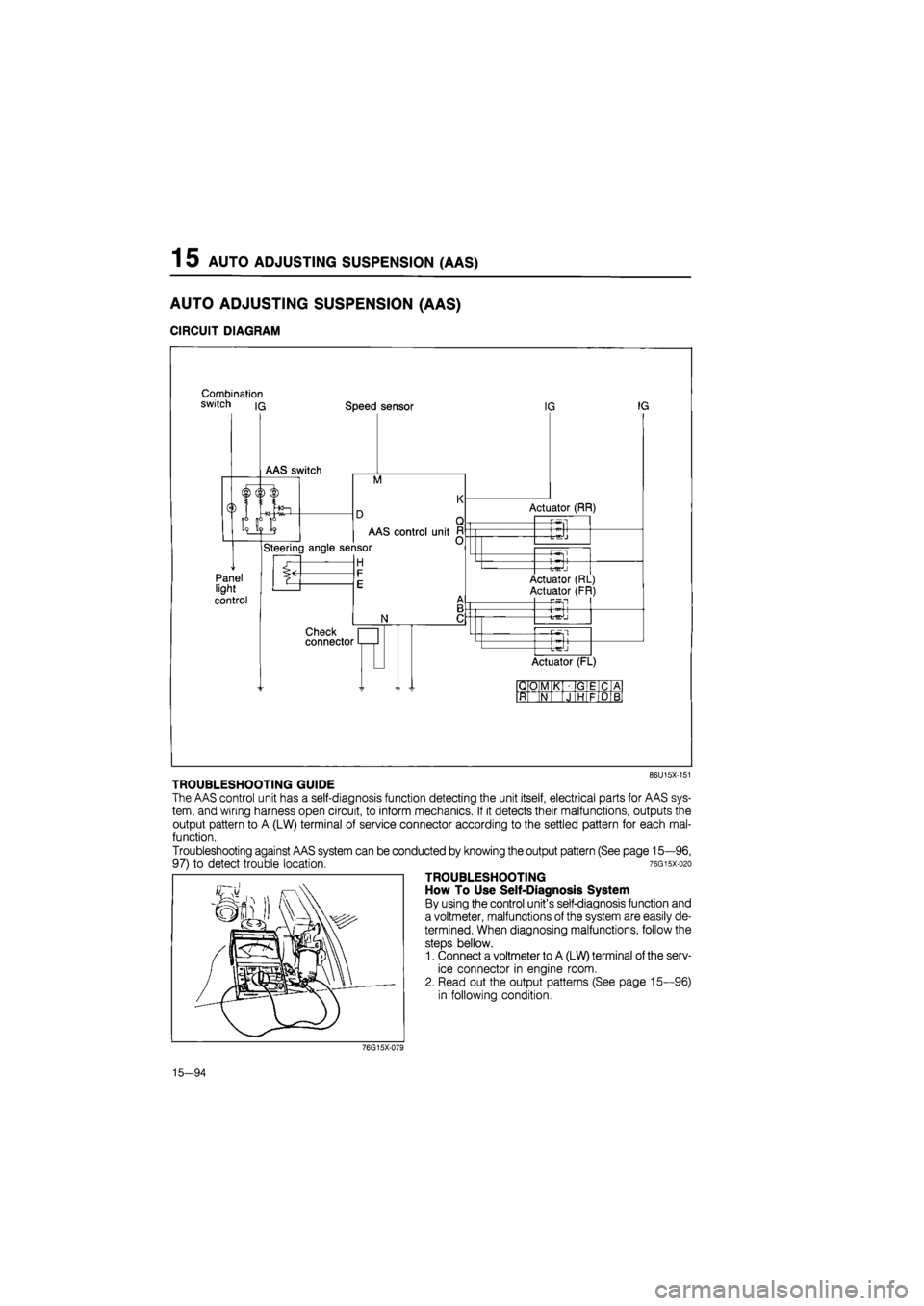
TROUBLESHOOTING GUIDE
The AAS control unit has a self-diagnosis function detecting the unit itself, electrical parts for AAS sys-
tem, and wiring harness open circuit, to inform mechanics. If it detects their malfunctions, outputs the
output pattern to A (LW) terminal of service connector according to the settled pattern for each mal-
function.
Troubleshooting against AAS system can be conducted by knowing the output pattern (See page 15—96,
97) to detect trouble location. 76gisx-o2o
TROUBLESHOOTING
How To Use Self-Diagnosis System
By using the control unit's self-diagnosis function and
a voltmeter, malfunctions of the system are easily de-
termined. When diagnosing malfunctions, follow the
steps bellow.
1. Connect a voltmeter to A (LW) terminal of the serv-
ice connector in engine room.
2. Read out the output patterns (See page 15—96)
in following condition.
76G15X-079
15—94
Page 1750 of 1865
AUTO ADJUSTING SUSPENSION (AAS) 1 5
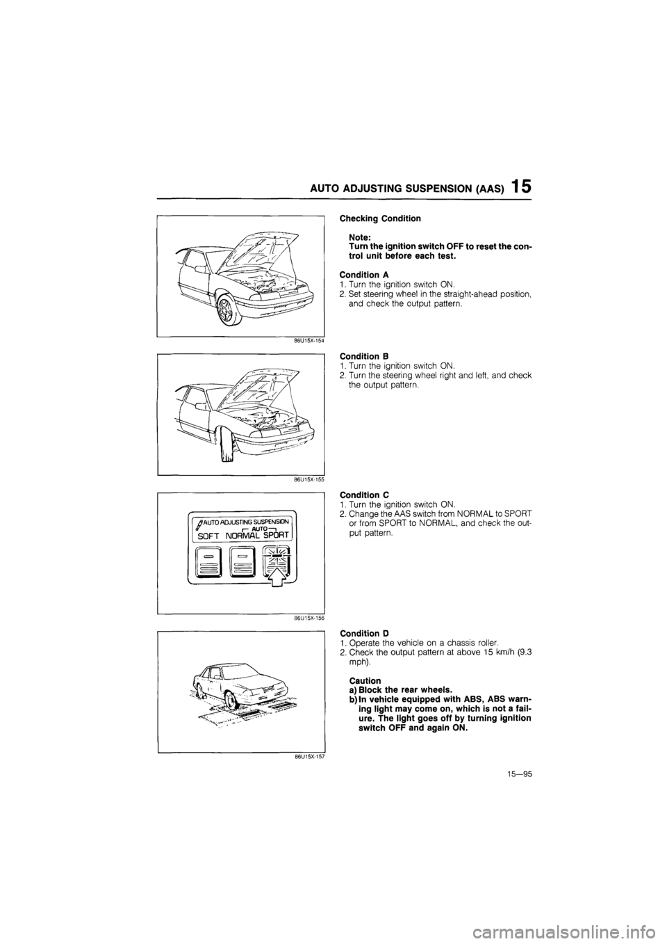
Checking Condition
Note:
Turn the ignition switch OFF to reset the con-
trol unit before each test.
Condition A
1. Turn the ignition switch ON.
2. Set steering wheel in the straight-ahead position,
and check the output pattern.
86U15X-154
Condition B
1. Turn the ignition switch ON.
2. Turn the steering wheel right and left, and check
the output pattern.
86U15X-155
•
/
AUTO ADJUSTING SUSPENSION I- AUTO—i SOFT NORMAL SPORT
Condition C
1. Turn the ignition switch ON.
2. Change the AAS switch from NORMAL to SPORT
or from SPORT to NORMAL, and check the out-
put pattern.
86U15X-156
Condition D
1. Operate the vehicle on a chassis roller.
2. Check the output pattern at above 15 km/h (9.3
mph).
Caution
a) Block the rear wheels.
b) In vehicle equipped with ABS, ABS warn-
ing light may come on, which is not a fail-
ure. The light goes off by turning ignition
switch OFF and again ON.
86U15X-157
15—95
Page 1792 of 1865
OUTLINE 16
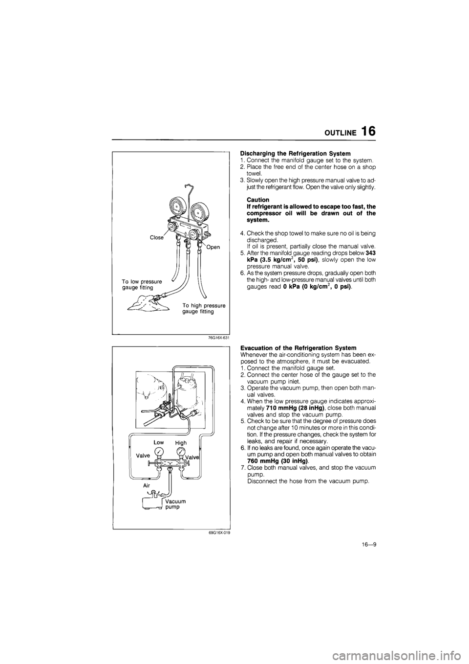
Discharging the Refrigeration System
1. Connect the manifold gauge set to the system.
2. Place the free end of the center hose on a shop
towel.
3. Slowly open the high pressure manual valve to ad-
just the refrigerant flow. Open the valve only slightly.
Caution
If refrigerant is allowed to escape too fast, the
compressor oil will be drawn out of the
system.
4. Check the shop towel to make sure no oil is being
discharged.
If oil is present, partially close the manual valve.
5. After the manifold gauge reading drops below 343
kPa (3.5 kg/cm2, 50 psi), slowly open the low
pressure manual valve.
6. As the system pressure drops, gradually open both
the high- and low-pressure manual valves until both
gauges read 0 kPa (0 kg/cm2, 0 psi).
76G16X-631
Evacuation of the Refrigeration System
Whenever the air-conditioning system has been ex-
posed to the atmosphere, it must be evacuated.
1. Connect the manifold gauge set.
2. Connect the center hose of the gauge set to the
vacuum pump inlet.
3. Operate the vacuum pump, then open both man-
ual valves.
4. When the low pressure gauge indicates approxi-
mately 710 mmHg (28 inHg), close both manual
valves and stop the vacuum pump.
5. Check to be sure that the degree of pressure does
not change after 10 minutes or more in this condi-
tion.
If
the pressure changes, check the system for
leaks, and repair if necessary.
6. If no leaks are found, once again operate the vacu-
um pump and open both manual valves to obtain
760 mmHg (30 inHg).
7. Close both manual valves, and stop the vacuum
pump.
Disconnect the hose from the vacuum pump.
69G16X-019
16-9
Page 1802 of 1865
COMPRESSOR 16
Escape groove
^ / / / / j / / ' / / / / /
' / / I / /
1 \ \ x Suction \ \ \/ valve
n W: \ / / y /
I u
Piston— ^
69G16X-044
69G16X-045
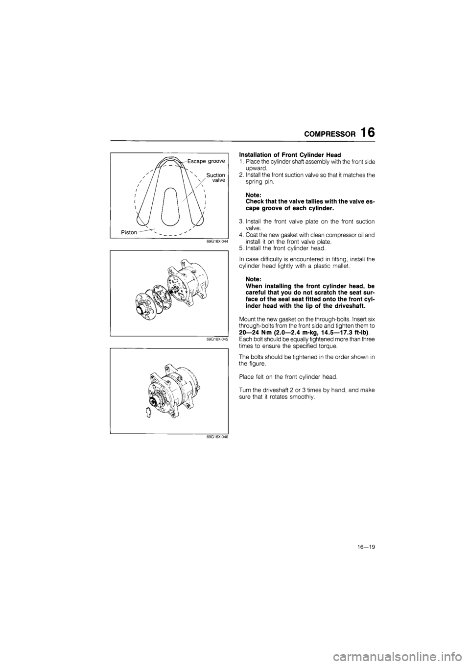
Installation of Front Cylinder Head
1. Place the cylinder shaft assembly with the front side
upward.
2. Install the front suction valve so that it matches the
spring pin.
Note:
Check that the valve tallies with the valve es-
cape groove of each cylinder.
3. Install the front valve plate on the front suction
valve.
4. Coat the new gasket with clean compressor oil and
install it on the front valve plate.
5. Install the front cylinder head.
In case difficulty is encountered in fitting, install the
cylinder head lightly with a plastic mallet.
Note:
When installing the front cylinder head, be
careful that you do not scratch the seat sur-
face of the seal seat fitted onto the front cyl-
inder head with the lip of the driveshaft.
Mount the new gasket on the through-bolts. Insert six
through-bolts from the front side and tighten them to
20—24 N m (2.0—2.4 m-kg, 14.5—17.3 ft-lb)
Each bolt should be equally tightened more than three
times to ensure the specified torque.
The bolts should be tightened in the order shown in
the figure.
Place felt on the front cylinder head.
Turn the driveshaft 2 or 3 times by hand, and make
sure that it rotates smoothly.
69G16X046
16—19