Page 1709 of 1865
15 HEADLIGHT
HEADLIGHT
CIRCUIT DIAGRAM
TROUBLESHOOTING
Leaded Fuel Model
76G15X-055
15-54
Page 1710 of 1865
HEADLIGHT 15
Unleaded fuel model
OK
Check
for
12V
at
"RB" wire (when low and/or "RW" wire (when high)
of
combination switch
6
pin con-nector
NG
Check
for
12V
at
"RB" wire (when low and/or "RW" wire (when high)
of
combination switch
6
pin con-nector
NG
Replace combination switch
Check
for
12V
at
"RB" wire (when low and/or "RW" wire (when high)
of
combination switch
6
pin con-nector
OK
Check the voltage between each terminal
of
the headlihgt relay and
a
body ground.
Terminal Voltage
a (RW) 12V
c(R) 12V
NQ Repair harness
(a
terminal
—
combination switch
to
headlight relay,
c
terminal
—
main fuse
to
headlight relay)
OK
OK —
Replace the bulb(s)
76G15X-053
INSPECTION
Headlight Relay
Check for continuity between terminals of the relay.
Connecting
to
Terminal
12V Ground a b c d
— —
O— —O
a b O— —-O
O—O: indicates continuity
76G15X-054
15—55
Page 1711 of 1865
1 5 PANEL LIGHT CONTROL
PANEL LIGHT CONTROL
CIRCUIT DIAGRAM
COMBINATION SW (Light Sw)
1 ? 3= o
5
B
*
SB c
52 "
o
-too u c E o E H Eil'y E 1 a tcsfi
86U15X-098
TROUBLESHOOTING
OK
Repair the wiring harness. (Fuse box
to
panel light controller, Panel light controller
to
body ground)
76G15X-056
15—56
Check the voltage between each terminal
of
the pan-el light controller connector and
a
body ground.
Terminal Voltage
B (RB) 12V
C(B) OV
Page 1712 of 1865
PANEL LIGHT CONTROL 15
INSPECTION
Panel Light Controller
1. Remove the panel light controller.
2. Check the voltage at D (GW) terminal of the panel
light controller.
Panel light controller Voltage
Min 10V
Max. OV
86U15X-100
15—57
Page 1727 of 1865
15 REAR WINDOW WIPER
CIRCUIT DIAGRAM
BATTERY MAIN FUSE X-01
X-01
REAR WIPER
&
WASHER SW GW [!]>• Control (Sectin Eb)
To Instrument Panel Light
D-01 Combination Sw [D]
LO
L B ±±±
LW
LB LR
D-02 Front Wiper Motor [F]
B
LR
LW
±±±
L LB L
D-03 Rear Wiper Sw [I] x
x GW
\±U±±
TTTT
(5 Door)
B
L BL
D-04 Rear Wiper Motor [R3]
^bGL (5Door)
D-05 Rear Washer Motor 1 D-06 Headlight Cleaner Sw
[
LY
RB
(5 Door)
LW GW
C-05 Washer Motor Assembly |Fj
LW
LY L
©I®T
T
LO
15-72
86U15X-127
Page 1732 of 1865
WINDSHIELD WIPER 15
CIRCUIT DIAGRAM
BATTERY
REAR WIPER
&
WASHER SW
GWIll^ Conlrol
. (Sectin ED)
To Instrument Panel Ligtil
D-01 Combination Sw
[
LO
L B ±±±
LW
LB LR
D-02 Front Wiper Motor [F]
B
LP LW
d±±
L LB L
D-03 Rear Wiper Sw
[I]
x
* GW
TTTT
(5 Door)
B
L BL RB
D-04 Rear Wiper Motor |R3]
(5 Door)
D-05 Rear Washer Motor [R]
^LG (5D°°r)
D-06 Headlight Cleaner Sw
LY
R0
LW GW
C-05 Washer Motor Assembly [F|
LW
LY L
f±±±1
wf 86U15X-135
15—77
Page 1738 of 1865
CRUISE CONTROL SYSTEM 1 5
CIRCUIT DIAGRAM
BATTERY
0
t
© o-
MAIN FUSE
X-05
—13 |F|-«-X-01
8QA X-01
X-02^ 15A JB-07 ® (1 OA) @
BW |D)
^-O
METER
From Combination Light Sw (Section Eb>
J*
TRB
[l|
MAIN SW
CLUTCH
SW
-BY ID]—
I iB-28 L-u^p——.L-1
~
—
LO,DI--JLO!D1
Lr
For West Germany
STOP SW
L-02nr iL-02
From Stop Light
.
checker (Section F)
GW
[I]
-BY [D] To Stop Light Checker GY.IDI
From Stop
Light Sw WG (Dj—
(Section F)
' '
L-01 Cruise Control Unit
|
B
L LW LO G GW
±±±LA±± TT
EC-Al
WG
MI LR
L-04 Cruise Control Sw [D]
L
LW
GR GY
GB
B
LR
L-05 Main Sw
[I]
riu^rii
^TTT1 GY BY B GW
L-02 Slop Sw
[
' (LV)
B-26 Clutch Sw (D]
LO
BY
m
RG LgB
L-03 Actuator
I
* GY G
r±±i
X GW GB
86U15X-147
15-83
Page 1739 of 1865

1 5 CRUISE CONTROL SYSTEM
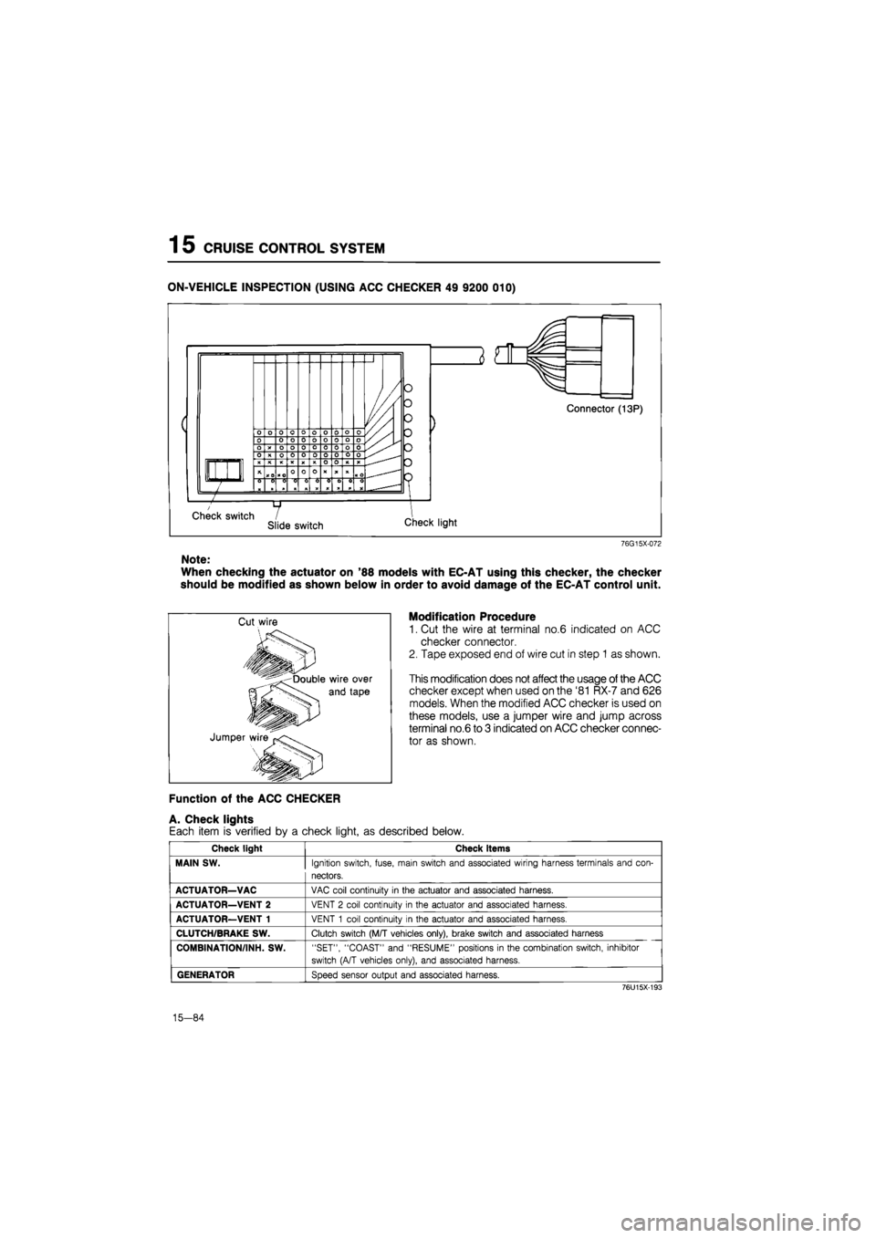
ON-VEHICLE INSPECTION (USING ACC CHECKER 49 9200 010)
76G15X-072
Note:
When checking the actuator on '88 models with EC-AT using this checker, the checker
should be modified as shown below in order to avoid damage of the EC-AT control unit.
Modification Procedure
1. Cut the wire at terminal no.6 indicated on ACC
checker connector.
2. Tape exposed end of wire cut in step 1 as shown.
This modification does not affect the usage of the ACC
checker except when used on the '81 RX-7 and 626
models. When the modified ACC checker is used on
these models, use a jumper wire and jump across
terminal no.6 to 3 indicated on ACC checker connec-
tor as shown.
Function of the ACC CHECKER
A. Check lights
Each item is verified by a check light, as described below.
Check light Check items
MAIN SW.
Ignition switch, fuse, main switch and associated wiring harness terminals and con-
nectors.
ACTUATOR—VAC
VAC coil continuity
in
the actuator and associated harness.
ACTUATOR—VENT 2
VENT
2
coil continuity
in
the actuator and associated harness.
ACTUATOR—VENT 1
VENT
1
coil continuity
in
the actuator and associated harness.
CLUTCH/BRAKE SW.
Clutch switch (M/T vehicles only), brake switch and associated harness
COMBINATION/INH. SW.
"SET", "COAST" and "RESUME" positions
in
the combination switch, inhibitor
switch (A/T vehicles only), and associated harness.
GENERATOR
Speed sensor output and associated harness.
76U15X-193
15-84