Page 1725 of 1865

15 REMOTE CONTROL MIRROR
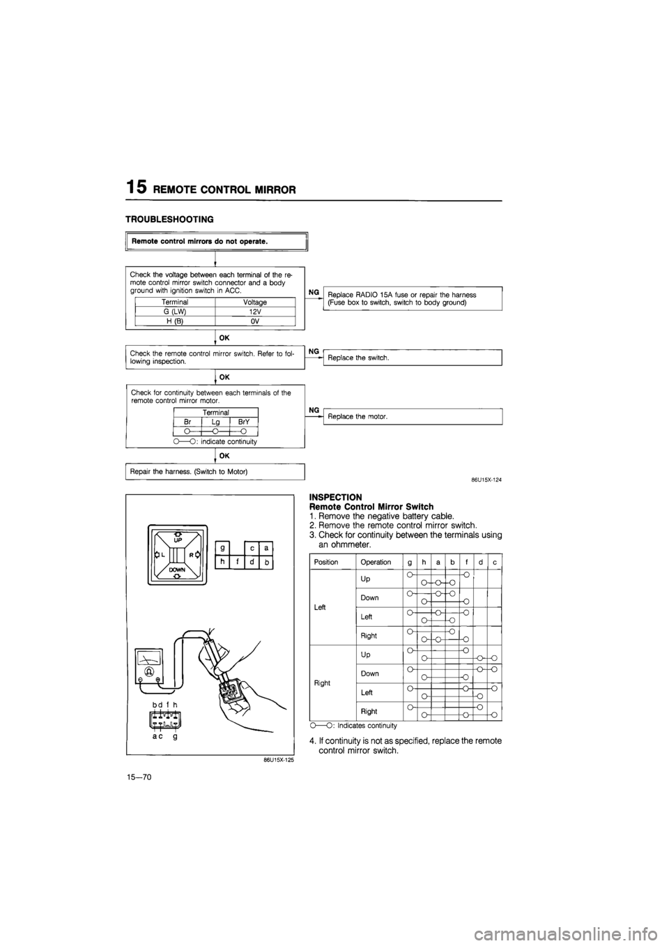
TROUBLESHOOTING
Terminal Voltage
G (LW) 12V
H(B) OV
OK
Check the remote control mirror switch. Refer
to
fol-lowing inspection.
OK
Check for continuity between each terminals
of
the remote control mirror motor.
Terminal
Br
O
Lg
-O-
BrY
-O
O—O: indicate continuity
Remote control mirrors do not operate.
Check the voltage between each terminal
of
the
re-
mote control mirror switch connector and
a
body ground with ignition switch
in
ACC.
NG
Replace RADIO 15A fuse
or
repair the harness (Fuse box
to
switch, switch
to
body ground)
NG
Replace the switch.
NG
Replace the motor.
OK
Repair the harness. (Switch
to
Motor)
86U15X-124
86U15X-125
INSPECTION
Remote Control Mirror Switch
1. Remove the negative battery cable.
2. Remove the remote control mirror switch.
3. Check for continuity between the terminals using
an ohmmeter.
Position
Left
Right
Operation
Up
Down
Left
Right
Up
Down
Left
Right
9
O
o-
o
o
o
o-
o-
o
O-O—o
o-
o-
o~o
o
o-
o
o-
o-o
•o -o
•o
f
•o
-o
-O
o
-o
-o
o
o
o-o
-o-o
-o
o
•o
o
O—O: Indicates continuity
4. If continuity is not as specified, replace the remote
control mirror switch.
15—70
Page 1727 of 1865
15 REAR WINDOW WIPER
CIRCUIT DIAGRAM
BATTERY MAIN FUSE X-01
X-01
REAR WIPER
&
WASHER SW GW [!]>• Control (Sectin Eb)
To Instrument Panel Light
D-01 Combination Sw [D]
LO
L B ±±±
LW
LB LR
D-02 Front Wiper Motor [F]
B
LR
LW
±±±
L LB L
D-03 Rear Wiper Sw [I] x
x GW
\±U±±
TTTT
(5 Door)
B
L BL
D-04 Rear Wiper Motor [R3]
^bGL (5Door)
D-05 Rear Washer Motor 1 D-06 Headlight Cleaner Sw
[
LY
RB
(5 Door)
LW GW
C-05 Washer Motor Assembly |Fj
LW
LY L
©I®T
T
LO
15-72
86U15X-127
Page 1732 of 1865
WINDSHIELD WIPER 15
CIRCUIT DIAGRAM
BATTERY
REAR WIPER
&
WASHER SW
GWIll^ Conlrol
. (Sectin ED)
To Instrument Panel Ligtil
D-01 Combination Sw
[
LO
L B ±±±
LW
LB LR
D-02 Front Wiper Motor [F]
B
LP LW
d±±
L LB L
D-03 Rear Wiper Sw
[I]
x
* GW
TTTT
(5 Door)
B
L BL RB
D-04 Rear Wiper Motor |R3]
(5 Door)
D-05 Rear Washer Motor [R]
^LG (5D°°r)
D-06 Headlight Cleaner Sw
LY
R0
LW GW
C-05 Washer Motor Assembly [F|
LW
LY L
f±±±1
wf 86U15X-135
15—77
Page 1738 of 1865
CRUISE CONTROL SYSTEM 1 5
CIRCUIT DIAGRAM
BATTERY
0
t
© o-
MAIN FUSE
X-05
—13 |F|-«-X-01
8QA X-01
X-02^ 15A JB-07 ® (1 OA) @
BW |D)
^-O
METER
From Combination Light Sw (Section Eb>
J*
TRB
[l|
MAIN SW
CLUTCH
SW
-BY ID]—
I iB-28 L-u^p——.L-1
~
—
LO,DI--JLO!D1
Lr
For West Germany
STOP SW
L-02nr iL-02
From Stop Light
.
checker (Section F)
GW
[I]
-BY [D] To Stop Light Checker GY.IDI
From Stop
Light Sw WG (Dj—
(Section F)
' '
L-01 Cruise Control Unit
|
B
L LW LO G GW
±±±LA±± TT
EC-Al
WG
MI LR
L-04 Cruise Control Sw [D]
L
LW
GR GY
GB
B
LR
L-05 Main Sw
[I]
riu^rii
^TTT1 GY BY B GW
L-02 Slop Sw
[
' (LV)
B-26 Clutch Sw (D]
LO
BY
m
RG LgB
L-03 Actuator
I
* GY G
r±±i
X GW GB
86U15X-147
15-83
Page 1760 of 1865
POWER DOOR LOCK 1 5
POWER DOOR LOCK
STRUCTURAL VIEW
CIRCUIT DIAGRAM
BATTERY
86U15X-171
15—105
Page 1762 of 1865
POWER DOOR LOCK 1 5
86U15X-173
INSPECTION
Power Door Lock Switch
1. Check for continuity of the switch with an
ohmmeter.
WG GB B
Lock
o O
Unlock
o O
O
O:
indicates continuity
2. If continuity is not as specified, replace the switch.
Power Door Lock Motor
1. Check operation of the door lock actuator when
the battery voltage is applied to the terminal.
Connecting
to
Door lock motor 12V ground Door lock motor
G R LOCK (Pull)
R G UNLOCK (Release)
2. If not, replace the door lock motor.
86U15X-174
15—107
Page 1764 of 1865
AUDIO SYSTEM 1 5
SYSTEM 8
AM/FM/LW RADIO WITH CASSETTE TAPE PLAYER
SYSTEM 9 AM/FM/SW RADIO WITH CASSETTE TAPE PLAYER
MEMO
lego n
TUNE SEEK tran 0 © O Q---M
METAL CD FADJfcBAL
O
•ulliSW VOL
TSL TRE-^SASS
ff— <] J AUTO REVERSE ZD r> r> / STOP EJECT
OI JO
(system 8 and 9)
-(t] Front left
-(t]Front right
-(I] Rear left
-£(]Rear right
REAR CONNECTOR VIEW
AM/SW or AM RADIO (MTR)
nn rr^
in to
L_J
O o w
I I
d
a Speaker-L ©
b Spsaker-L f)
c Speaker-R (+)
d Spaaker-R (p)
a
b Illumination
c Battery (?)
76G15X-022
15-109
Page 1765 of 1865

15 AUDIO SYSTEM
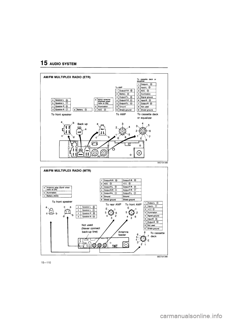
AM/FM MULTIPLEX RADIO (ETR)
To front speaker
To cassette deck or equalizer
a Speaker-L © a Motor antenna (Earthed when radio is ON) b Speaker-L ©
a Motor antenna (Earthed when radio is ON)
c Speaker-R © b Illumination
d Speaker-R © a Battery © c ACC ©
1 Output-L ©
To AMP 2 Input-L ©
1 Output-F-R © 3 ACC ©
2 Battery © 4 Illumination
3 Output-F-L © 5 Signal ground
4 Output-F-R © 6 Input-R ©
5 Output-F-L © 7 Output-R ©
6 Ground 8 Not used
E Shield ground E Shield ground
To AMP To cassette deck
or equalizer
56G15X085
AM/FM MULTIPLEX RADIO (MTR)
a Antenna relay (Earth when radio is ON)
b Illumination
c Battery (ACC)
To front speaker
c a
1 Output-R-R © Output-F-R ©
2 ACC © ACC ©
3 Output-R-L © Output-F-R ©
4 Output-R-R © Output-F-R ©
5 Output-R-L © Output-F-L ©
6 Ground Ground
E Shield ground Shield ground
a Speaker-L ©
b Speaker-L ©
c Speaker-R ©
d Speaker-R ©
To rear AMP To front AMP
Not used
(Never connect
back-up line)
1 Output-L ©
2 Input-L ©
3 ACC ©
4 Illumination
5 Signal ground
6 Input-R ©
7 Output-R ©
8 Not used
E Shield ground
To cassette
deck
56G15X-086
15-110