Page 1640 of 1865

SLIDING SUNROOF 14
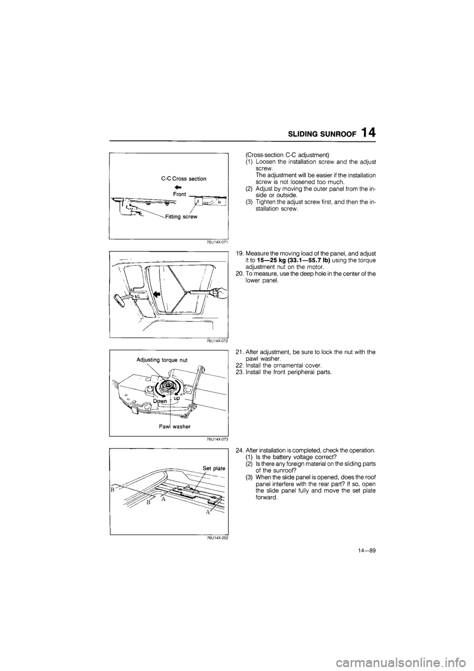
(Cross-section C-C adjustment)
(1) Loosen the installation screw and the adjust
screw.
The adjustment will be easier if the installation
screw is not loosened too much.
(2) Adjust by moving the outer panel from the in-
side or outside.
(3) Tighten the adjust screw first, and then the in-
stallation screw.
76U14X-071
19. Measure the moving load of the panel, and adjust
it to 15—25 kg (33.1—55.7 lb) using the torque
adjustment nut on the motor.
20. To measure, use the deep hole in the center of the
lower panel.
76U14X-072
Adjusting torque nut
Pawl washer
21. After adjustment, be sure to lock the nut with the
pawl washer.
22. Install the ornamental cover.
23. Install the front peripheral parts.
76U14X-073
24. After installation is completed, check the operation.
(1) Is the battery voltage correct?
(2) Is there any foreign material on the sliding parts
of the sunroof?
(3) When the slide panel is opened, does the roof
panel interfere with the rear part? If so, open
the slide panel fully and move the set plate
forward.
76U14X-202
14—89
Page 1643 of 1865
1 4 WINDSHIELD WIPER
86U14X-168
86U14X-169
86U14X-170
REMOVAL
1. Disconnect the negative battery cable.
2. Remove the wiper arms.
3. Remove the lower molding.
4. Remove the cover.
5. Disconnect the wiper link from the motor.
Caution
Do not remove the motor arm unless neces-
sary. The motor arm position on the motor
shaft decides the automatic stop position,
(lowest position of the wiper arm)
6. Disconnect the connector.
7. Remove the wiper motor.
8. Remove the wiper link assembly mounting bolts.
9. Lift the wiper link assembly out from the left side
(driver's side) service hole.
86U14X-171
14—92
Page 1646 of 1865
REAR WINDOW WIPER 14
86U14X-176
86U14X-178
REMOVAL
1. Disconnect the negative battery cable.
2. Remove the wiper arm.
3. Open the rear hatch.
4. Remove the rear hatch trim (upper, side and lower).
5. Remove the rear hatch screen.
Note
Remove the screen carefully so that it may be
reused.
6. Disconnect the rear wiper motor connector.
7. Remove the rear wiper motor.
INSTALLATION
Install in the reverse order of removal.
86U14X-179
14—95
Page 1660 of 1865
INTRODUCTION 15
69G15X-006
4BG15X-003
69G15X-007
/Wire
Shield braid wire
Insulation
Replacement of Fuse
1. When replacing a fuse, be sure to replace it with
one of the specified capacity.
If, after a fuse has been replaced, it fails again, there
is probably a short in the circuit, and the wiring
should be checked.
2. Be sure the negative battery terminal is disconnect-
ed before replacing a main fuse.
3. When replacing a fuse, use the supplied fuse puller
in the fuse box cover.
Thin Insulation Wire
To reduce the weight of the wiring harness, a thin
coating of high resistance insulation material is used.
Shielded braid wire
This wire is used to prevent a malfunction in impor-
tant circuits that are susceptible to outside signals or
interference.
Eg.
Ignition coil
02 sensor
69G15X-008
15—5
Page 1661 of 1865
15 INTRODUCTION
ELECTRICAL SYMBOLS
Switches and Relays
There is an NC (normally closed) and NO (normally open) indication for switches and relays; this indi-
cates the condition when there has been no change of operating conditions.
Relay
NO type relay NC type relay
Switch
NO switch NC switch
Not
in
operation (No power supply)
—Jtfiifij —o o—
Flow Stop Flow
In operation (Power supply)
^
^aijuiy—'
Flow
l=3X
Stop
Flow
Stop
Other Electrical Symbols
Holder
Box —
© ©
Holder
Box —
Holder
Box —
BATTERY BODY GROUND FUSE FUSIBLE LINK
(£)
* 1 fc
MOTOR COIL, SOLENOID RESISTOR VARIABLE RESISTOR
1
ii
-L ©
THERMISTER DIODE CONDENSER LIGHT
1
TRANSISTOR SPEAKER CIGARETTE LIGHTER HEATER
69G15X-009
15—6
Page 1665 of 1865
5
IGNITION
SWITCH
76G15X-026
B IG1
ST ST •S
Key reminder switch
~
Key reminder switch
ON
Lock
ACC
ACC
69G15X-014
REPLACEMENT
Disconnect the negative battery terminal. 30, 40 and
60A fuses: pull out and push in a new fuse.
80A fuse:
1. Remove the main fuse box.
2. Open the cover.
3. Remove the terminal.
4. Pull out and push in a new fuse.
IGNITION SWITCH
INSPECTION
1. Use an ohmmeter to check continuity of the termi-
nals of the switch.
2. If continuity is not as specified, replace the switch.
-^Terminal
Position"""-""---^^ B ACC IG2 IGi ST c d
LOCK Remove LOCK Insert 0--0
ACC O--0 O--0
ON O--O o--O o--o
ST r -O O--o ST -O O--o
): Indicates continuity
15—10
Page 1698 of 1865

CENTRAL PROCESSING UNIT (CPU) 1 5
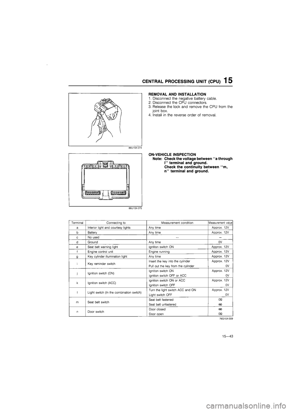
REMOVAL AND INSTALLATION
1. Disconnect the negative battery cable.
2. Disconnect the CPU connectors.
3. Release the lock and remove the CPU from the
joint box.
4. Install in the reverse order of removal.
ON-VEHICLE INSPECTION
Note: Check the voltage between "a through
I" terminal and ground.
Check the continuity between "m,
n" terminal and ground.
86U15X-075
Terminal Connecting
to
Measurement condition Measurement value
a Interior light and courtesy lights Any time Approx.
12V
b Batterv Anv time Approx.
12V
c No used
— —
d Ground Anv time OV
e Seat belt warning light Ignition switch
ON
Approx.
12V
f Enaine control unit Enaine runnina Approx.
12V
g Key cylinder illumination light Any time Approx.
12V
i Key reminder switch Insert the key into the cylinder
Pull out the key from the cylinder
Approx.
12V
OV
j Ignition switch (ON) Ignition switch
ON
Ignition switch OFF
or
ACC
Approx.
12V
OV
k Ignition switch (ACC) Ignition switch
ON or
ACC
Ignition switch OFF
Approx.
12V
OV
I Light switch (In the combination switch) Turn the light switch ACC and
ON
Light switch OFF
Approx.
12V
OV
m Seat belt switch Seat belt fastened
Seat belt unfastered
OQ
OO
n Door switch Door closed
Door open
OO
on
76G15X-009
15—43
Page 1717 of 1865
15 POWER WINDOW
CIRCUIT DIAGRAM
(Coupe/MX-6)
BATTERY
" 76G15X-010
(For Sedan and Hatchback)
Q @ X-01 X-01 0 o-l—^-O^O-S
1 RATTFRY
BOA
X-05 3 [Fl
IG:
POWER WINDOW
SW M-01'
ion I
X-19
X-19 JB-09® JB-07®
R [Drl]
£
BR
[R]—o-»-BW
[DJ—1 30A © pmJro w
nrhif II U U U J closeV open\ closeV open\ close\ openv closeV open
|—' 1-] J ; •»---" ^ £ : ~ ^
SIT if I?' Ill m II II
GW [DM J
X-19 4
RW [Drl 1 I LW[brl] YW[Drl]
GY (brl)WR [DM[ BL [Dl1]
RL [Drl |
"
GW [R]
RW
X-21
X-18:
=
|
Ir [R[ Ir BL [R1 BL
RW [Dr2]
GW [Or2j
M-03J
LW (Dr3[ BL [Dr2]
M-05:
rffl
GY [R] WR [I
BL [Dr3] YW [DM]
M-05 R[Di2] G[Dr2[
R [Dr3[ L [fir3[ R [Dr4] L [Dr4|
POWER WINDOW SW
POWER WINDOW MOTOR (FR) (RL) (PR)
15-62