Page 250 of 1865
1 C DISASSEMBLY (TIMING BELT)
Injection pump pulley
1. Put two bolts of 35—40 mm (1.4—1.6 in) length
into the arms of the injection pump pulley and af-
fix them in the threaded hole of the injection pump
bracket.
2. Loosen the injection pump pulley lock bolt.
3. Separate the injection pump pulley from the injec-
tion pump shaft with the SST.
Camshaft pulley
1. Hold the camshaft with a wrench (29 mm, 1.14 in)
and loosen the camshaft pulley lock bolt.
Caution
Do not damage the cylinder head edge with
the wrench.
2. Separate the camshaft pulley from the camshaft
with the SST.
Caution
Do not hit the camshaft pulley with a hammer.
Rear camshaft pulley
Remove the rear camshaft pulley in the same man-
ner used for camshaft pulley.
4BG01B-087
76G01C-081
1C—38
Page 251 of 1865
DISASSEMBLY (INJECTION PUMP) 1 C
INJECTION PUMP
76G01C-082
1. No.3 engine mount and idler
2. Injection pipe
3. Injection pump
4. Oil level gauge and stay
5. Oil pipe
6. Fuel feed pipe
7. Oil pressure switch
8. Water pipe
9. Water pump
Disassembly Note
Injection pump
Remove the injection pump with its brackets.
If separate them, adjust the injection timing after in-
stalling the timing belt referring to Section 4D.
76G01C-083
1C-39
Page 255 of 1865
DISASSEMBLY (CYLINDER BLOCK) 1 C
CYLINDER BLOCK—I
76G01C-091
1. Clutch cover
2. Clutch disc
3. Flywheel
4. End plate
5. Oil pan
6. Oil strainer
7. Stiffener (RF-CX)
8. Rear cover
9. Timing belt pulley
10. Oil pump assembly
Flywheel
1. Install the SST to the flywheel.
2. Remove the clutch cover, clutch disc and flywheel.
Timing belt pulley
1. Reverse the direction of the SST.
2. Remove the timing belt pulley.
76G01C-092
1C—43
Page 272 of 1865
1C INSPECTION AND REPAIR
Rolled fillet
Crankpin journal diameter undersize mm (in)
Bearing size Journal diameter
0.25 undersize 50.690—50.705 (1.9957-1.9963)
0.50 undersize 50.440—50.455 (1.9858-1.9864)
0.75 undersize 50.190-50.205 (1.9760-1.9766)
Caution
Do not grind the rolled fillet area.
76G01C-145
Main Bearing and Connecting Rod Bearing
Check the main bearings and the connecting rod
bearings for peeling, scoring, or other damage.
79G01C-077
Timing Belt
1. Replace the timing belt if there is any oil or grease
on it.
2. Check the timing belt for damage, wear, peeling,
cracks, or hardening. Replace if necessary.
86U01X-113
Caution
a) Never forcefully twist, turn inside out, or
bend the timing belt.
b) Be careful not to allow oil or grease on the
belt.
86U01X-114
1C—60
Page 273 of 1865
INSPECTION AND REPAIR 1C
86U01X-115
Timing Belt Tensioner and Idler Pulley
Check the timing belt tensioner and idler pulley for
smooth rotation and abnormal noise. Replace if
necessary.
Caution
Do not clean the tensioner with cleaning
fluids. If necessary, use a soft rag to wipe it
clean, and avoid scratching it.
Timing Belt Tensioner Spring
Check the free length of the tensioner spring. Replace
if necessary.
Free length:
52.6 mm (2.071 in)
76G01C-251
Timing Belt Pulley and Camshaft Pulley
Inspect the pulley teeth for wear, deformation, or other
damage. Replace if necessary.
Caution
Do not clean the pulley with cleaning fluids.
If necessary, use a rag to wipe it clean.
Timing Belt Cover
Inspect the timing belt covers for damage or cracks.
Replace if necessary.
76G01C-146
1C—61
Page 284 of 1865
1 C ASSEMBLY (CYLINDER BLOCK)
Clutch Disc and Clutch Cover
Install the clutch disc and clutch cover using the SST.
(Refer to Section 6.)
Tightening torque:
18—26 Nm (1.8—2.7 m-kg, 13—20 ft-lb)
76G01C-169
Timing Belt Pulley
1. Install the timing belt pulley with the semicircular
(woodruff) key.
Tightening torque:
179—193 Nm (18.3—19.7 m-kg,
132—142 ft-lb)
4BG01B-180
2. Release the ring gear brake, turn the flywheel,
move the No.
1
piston to the top position, and then
turn it approximately 45° in the forward direction.
Caution
This is to prevent damage to the pistons and
valves when the cylinder head is installed.
4BG01B-181
1C—72
Page 288 of 1865

1 C ASSEMBLY (CYLINDER HEAD)
6. Apply a coat of engine oil to the new oil seal lip
and insert it.
76G01C-253
76G01C-173
Glow cord
Glow plug
76G01C-174
7. Tighten the camshaft cap nuts evenly in order
shown in the figure.
Tighten torque:
20—26
N m
(2.0—2.7 m-kg, 14—20 ft-lb)
Note
The adjustment of the valve clearance should
be made only after the camshaft pulley injec-
tion pump pulley and timing belt have been
installed.
Glow Plug and Glow Cord
1. Install the glow plugs.
Tightening torque:
15—20 Nm (1.5—2.0 m-kg, 11—15 ft-lb)
2. Install the glow cord.
Tightening torque:
0.8—1.5 Nm (8.0—15 cm-kg, 7—13 in-lb)
Injection Nozzle and Leak Pipe
1. Install the new corrugated washers and the new
copper gaskets in position.
2. Install the injection nozzles.
Tightening torque:
59—69 Nm (6.0—7.0 m-kg, 43—51 ft-lb)
Note
The corrugated washers and copper gaskets
must be replaced with new ones each time the
injection nozzles are removed.
3. Install the leak pipe.
Tightening torque:
31—44
N m
(3.2—4.5 m-kg, 23—33 ft-lb)
76G01C-175
1C—76
Page 292 of 1865
1 C ASSEMBLY (INJECTION PUMP)
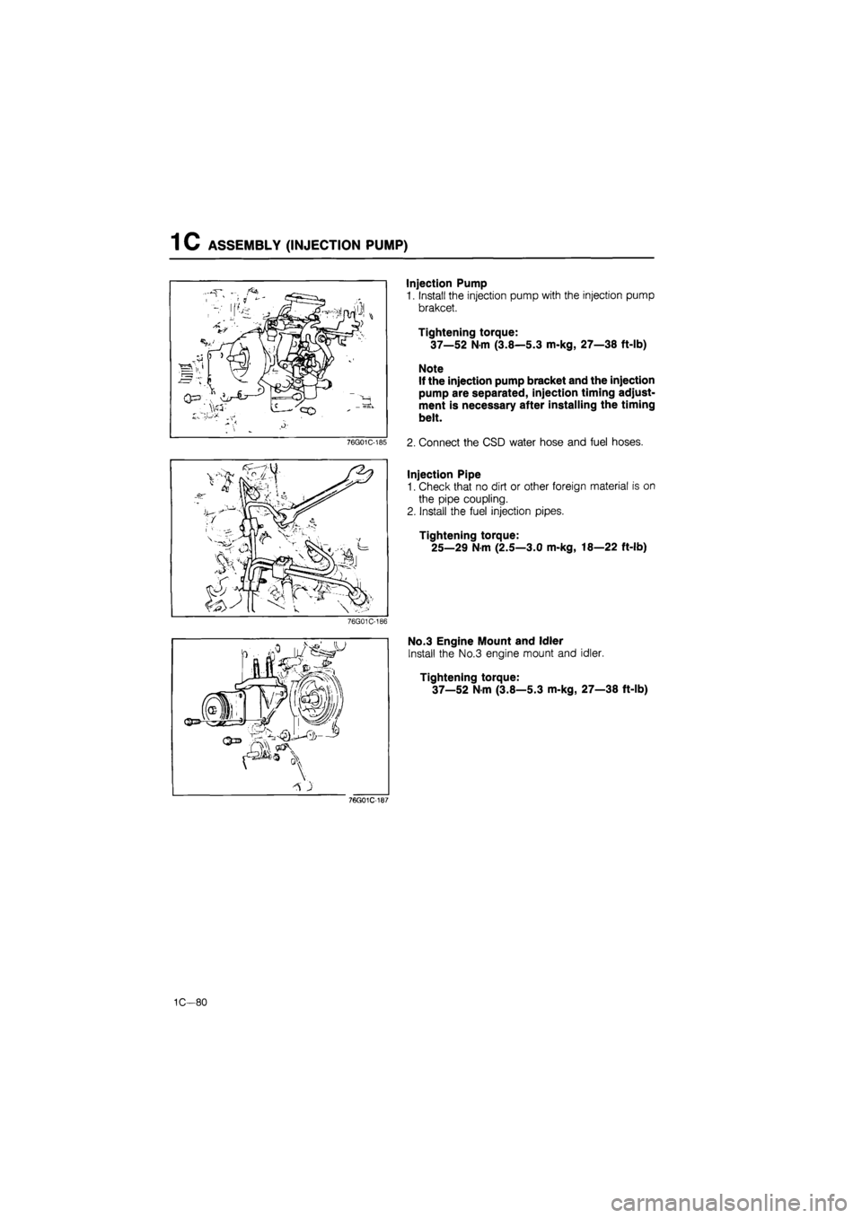
Injection Pump
1. Install the injection pump with the injection pump
brakcet.
Tightening torque:
37—52
N m
(3.8—5.3 m-kg, 27—38 ft-lb)
Note
If the injection pump bracket and the injection
pump are separated, injection timing adjust-
ment is necessary after installing the timing
belt.
2. Connect the CSD water hose and fuel hoses.
Injection Pipe
1. Check that no dirt or other foreign material is on
the pipe coupling.
2. Install the fuel injection pipes.
Tightening torque:
25—29 Nm (2.5—3.0 m-kg, 18—22 ft-lb)
76G01C-186
m.«JL
Qja .
^ }
No.3 Engine Mount and Idler
Install the No.3 engine mount and idler.
Tightening torque:
37—52
N
m (3.8—5.3 m-kg, 27—38 ft-lb)
76G01C-187
1C—80