Page 446 of 1865

IGNITION TIMING CONTROL SYSTEM 4A
TROUBLESHOOTING
Check the condition of the wiring harness and components before checking the sensors or switches.
\\ Possible cause , . Engine control unit terminal
\ Page
rater
thermo
switch
itake
manifold)
'ater
thermo
switch
Iadiator)
hibitor
switch
Solenoid
valve
(Ignition
timing
contra
0) >
5 >> n
acuum
control
unit
Ustributor)
Symptom \J
•S-
o 5 t c
Solenoid
valve
(Ignition
timing
contra
O > B 1F 2A 2F 2H 2M Symptom \J 4A—95 4A—95 4A—93 4A—81 4A—82 Section 5 4A—85 4A--86
Poor accelera-
tion, hesitation, 5 6 4 2 3 1 11 7 8 9 10 or lack of power
Fails emission test 4 5 3 2 — 1 10 6 7 8 9
76G04A-161
Solenoid Valve (Ignition Timing Control)
1. Disconnect the vacuum hose from the solenoid
valve and vacuum pipe.
2. Blow through the solenoid valve from vacuum hose
A.
3. Check that air flows from port B.
76G04A-162
4. Disconnect the solenoid valve connector.
5. Connect 12V and a ground to the terminals of the
solenoid valve.
6. Blow through the solenoid valve from vacuum hose
A.
7. Check that air flows from the valve air filter.
76G04A-163
4 A—81
Page 447 of 1865
4 A IGNITION TIMING CONTROL SYSTEM
Delay Valve
1. Remove the delay valve.
2. Connect a vacuum pump to the valve as shown
in the figure.
3. Apply vacuum and check that it is released
gradually.
4. If not correct, replace the delay valve.
76G04A-164
5. Connect a vacuum pump to the valve as shown
in the figure.
6. Apply vacuum and check that it is not held.
7. If not correct, replace the delay valve.
76G04A-165
4A—82
Page 449 of 1865
4A CONTROL SYSTEM
RELATIONSHIP CHART
O: Related
X
: Not
related
IGNITION COIL
X X
O O O
X
O
X
WATER
THERMO
SWITCH
RADIATOR O O
X X X X
o O WATER
THERMO
SWITCH INTAKE
MANIFOLD o
X X X X
O o
X
VACUUM SWITCH
X X X X X X X
O
IDLE SWITCH
X X
O O O
X X X
A/C SWITCH
X X X X X
O
X X
P/S SWITCH
X X X X X X X X
E/L SWITCHES
/ Headlight Switch
( Rear defroster switch
J
\ Fan speed control switch
/
X X X X X
O
X X
INHIBITOR SWITCH
X X X X X
O O
X
ENGINE CONTROL UNIT
X
o O O O O o O
\
INPUT
DEVICE
AND
ENGINE
CONTROL
UNIT
OUTPUT
DEVICE
PTC
HEATER
CHOKE
OPENER
(FE
and
F8
—
ECE,
Hong
Kong,
&
Singapore)
COASTING
LEANER
COAST
ENRICHMENT
SOLENOID
VALVE
AIR
BYPASS
SOLENOID
VALVE
IDLE-UP
SOLENOID
VALVE
IGNITION
TIMING
CONTROL
SYSTEM
MAIN
AIR
BLEED
CONTROL
SYSTEM
*
FE
8Valve—Unleaded Fuel:
O
(Related)
General and
FE
12Valve—ECE, Hong Kong, Singapore:
X
(Not related)
76G04A-167
4A—84
Page 451 of 1865

4A CONTROL SYSTEM
ENGINE CONTROL UNIT
Check the engine control unit terminal voltages with
a voltmeter.
Caution
a) Warm up the engine before checking the
control unit.
b) If the proper voltage is not obtained, check
the wiring, connections and finally, check
the component.
FE and F8 Engine — ATX (ECE, Hong Kong, and Singapore)
Terminal
(Wire color) Connected to Condition Voltage
1A
(BW)
Ignition switch Ignition switch ON. Battery voltage
m
ST
'-O
Solenoid valve (Main
air
bleed control) Others Battery voltage
m
ST
'-O
Solenoid valve (Main
air
bleed control) Radiator coolant temperature below 17°C (63°F)
or
intake manifold vacuum more than 200 mmHg (7.9 inHg)
Below 1,5V
1C (GO) Solenoid valve (Choke opener) Radiator coolant temperature below 17°C (63°F)
or
during cranking and
27
sec. after engine starts Below 1,5V
Others Battery voltage
1D
(GL)
Air bypass solenoid valve Idle switch OFF and engine speed above approx. 2,100 rpm Below 1,5V
Others Battery voltage
1E
— — —
1F
(G) Solenoid valve (Ignition timing control system)
Radiator coolant temperature above 17°C (63°F),
en-
gine coolant temperature below 72°C (162°F), inhibi-tor switch OFF and engine speed below 2,300
rpm
Below 1.5 V
Others Battery voltage
1G
— — —
1H
(LW) Solenoid valve (A/C) A/C switch
ON
and engine speed below approx. 2,300
rpm
Below 1,5V
Others Battery voltage
11
(YW) Idle-up solenoid valve Inhibitor switch OFF and, headlight switch ON, rear
defroster switch ON, fan speed control switch
is 3rd
or 4th position, A/C operated,
or
engine coolant tem-
perature below 72°C (162°F)
Below 1,5V
Others Battery voltage
1J
(B)
Ground
—
Below 1,5V
9 MSSirSl
ivj
A 1
k *
76G04A-169
4A—86
Page 469 of 1865
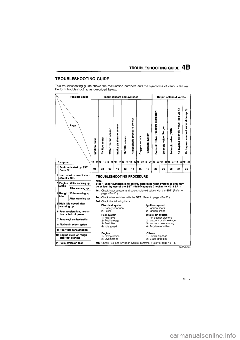
TROUBLESHOOTING GUIDE 4B
TROUBLESHOOTING GUIDE
This troubleshooting guide shows the malfunction numbers and the symptoms of various failures.
Perform troubleshooting as described below.
Possible cause
Symptom
Input sensors and switches
o>
Q.
C
0
Jh c 01
4B-14
a> 4)
E
o
4B-1S
o in c « m o E k_ 0) c.
0 <0 £
4B-16
o CO c a> 0) o E
a>
.x
co
4B-17
o 10 c a) co
4B-18
o in c a> (0
o> o> a>
a) £ a VI o E
4B-19
0 <0 c a> 0) c a> 01
S? o
4B-20
E a> in (0
o 10 A •o 0) 0> u.
4B-21
Output solenoid valves
o «
3 O) 0)
0) 0) 01
0> > 10 >
•o o c V o tt)
4B-22
0)
OI
0> > CO >
TJ
O c 0> o CO
4B-23
oc O u
o> > 75 >
•o o c a> o 05
4B-23
0 a. 3 1
2
0) > (0 >
"D O
o 0> in in a a >. £
4B-23
ffl a 3 • a>
2
a> > 10 >
"O o c a> o
CO Q. >. JO
4B-24
Fault Indicated by SST
Code No. 01 08 09 10 12 14 15 17 25 26 28 34 35
Hard start or won't start
(Cranks OK)
Engine stalls
Rough
idle
While warming up
After warming up
While warming up
After warming up
High idle speed after
warming up
TROUBLESHOOTING PROCEDURE
Note
Step 1 under symptom is to quickly determine what system or unit may be at fault by use of the SST. (Self-Diagnosis Checker 49 H018 9A1)
1st:
Check input sensors and output solenoid valves with the
SST.
(Refer
to
page 4B—10.)
2nd:
Check other switches with the
SST.
(Refer
to
page 4B—26.)
3rd:
Check the following items:
11
Poor acceleration, hesita-
tion or lack of power
Runs rough on deceleration
Afterburn in exhaust system
Poor fuel consumption
Engine stalls or rough after hot starting
Electrical system
1) Battery condition
2) Fuses
Fuel system
1) Fuel level 2) Fuel leakage
3) Fuel filter 4) Idle speed
Engine
1) Compression 2) Overheating
Ignition system
1) Ignition spark 2) Ignition timing
Intake air system
1)
Air
cleaner element 2) Vacuum
or air
leakage 3) Vacuum hose routing
4) Accelerator cable
Others
1) Clutch slippage 2) Brake dragging
Fails emission test 4th:
Check Fuel and Emission Control Systems. (Refer
to
page 4B—8.)
76G04B-003
4B—7
Page 491 of 1865
IDLE ADJUSTMENT 4B
76G04B-034
76G04B-035
Idle mixture
Automatic
Control
Function
Engine Control Unit
IDLE
ADJUSTMENT
IDLE SPEED
Preparation
1) Check the condition of the engine (plugs, leaks in
hoses, etc.).
2) Make sure all accessories are OFF.
3) Warm up the engine and run it for three minutes
at 2,500—3,000 rpm in neutral.
4) Check the initial ignition timing and adjust if
necessary.
Inspection and Adjustment
Caution
Disconnect the air bypass solenoid connec-
tor when checking and adjusting the idle
speed.
1. Check that the idle speed is within specification.
Specification:
MTX—800 +58 rpm
ATX—900 +58 rpm (P range)
2. If the idle speed is not within specification, remove
the blind cap from the throttle body and adjust it
by turning the air adjust screw.
IDLE MIXTURE
Because an automatic compensation function
for air/fuel mixture is built into the engine con-
trol unit, it is not necessary to check and adjust
the idle mixture.
86U04A-049
4B-29
Page 546 of 1865
4B CONTROL SYSTEM
RELATIONSHIP CHART
Input Devices and Output Devices
BRAKE LIGHT SWITCH O X X X X X X X X X
ELECTRICAL LOAD CONTROL UNIT X X X X X X X X O X
P/S PRESSURE SWITCH* X X X X X X X X O X
A/C SWITCH O X X X X O O X X O
IGNITION SWITCH
(STA
POSITION) O O X O X X X X O O
INHIBITOR SWITCH o X X X O X X X X O
NEUTRAL
AND
CLUTCH SWITCH o X X X X X X X X O
OXYGEN SENSOR o X X X X X X X X X
WATER THERMO SWITCH (RADIATOR) o X X X O X X X X X
ATMOSPHERIC PRESSURE SENSOR o X X X X O X O O X
INTAKE
AIR
THERMO SENSOR o X X O X X X O O X
WATER THERMO SENSOR o X X O O O X X o X
IDLE SWITCH o o X O X X X X o X
THROTTLE SENSOR o O X X O X X X X O
AIR FLOW METER o X X X X O X X X X
IGNITION COIL o O X O O O X X o O
INPUT
DEVICES
OUTPUT
DEVICES
FUEL
INJECTION
AMOUNT FUEL
INJECTION
TIMING
PRESSURE
REGULATOR
EGR
PURGE
IDLE-UP
(A)*
IDLE-UP
(B)
IDLE-UP
(C)
rr
INPUT
DEVICES
OUTPUT
DEVICES
INJECTOR
AIR
VALVE
SOLENOID
VALVE
AIR
BYPASS
SOLENOID
VALVE
AIR
CONDITIONEI
76G04B-108
4B-84
Page 570 of 1865

TROUBLESHOOTING GUIDE 4C
TROUBLESHOOTING GUIDE
This troubleshooting guide shows the malfunction numbers and the symptoms of various failures.
Perform troubleshooting as described below.
Input sensors and switches
Possible cause
Page
Symptom and No. CO
T O
a c OI '35
O
I o Tt
o in
a> in
8 c
o
o (A C 0) in
S o
I o
c $
o E
00 T-I O
T o I-ij
o in c at at o E « £
2 a
o>
o
e o •C H
I O
o at e 0) o>
o CM I o
E a> «-» in >• in a o (0 A •o a> d>
CM I o
Output solenoid valve
o> > <0 >
2
—.
§8 £ c
O O
(0
O
CVI I o
c 0 u « 01 w 3 a
o z «
> 73 >
"O o c a> o (/)
CM CM
o
O o 0) o>
Q. CM
V >
CB >
•o o c 4) o CO
CM CM
O
oc (9 UJ, g
n >
•o o c a> o <0
CO CM
O
o o •o w « a in «
2
s
5 •o o c »
o CO
CO CM
o
n
£
o in c a* (A c a> o>
o
CM
O
w q) t « s > c w QJ O)
"8 g> IS n « £
a> >
a >
T3 O C ai o CO
TT CM
o
Fault Indicated by SST
Code No. 02 03 05 *i 08 09 11 12 *2 15 • 2 17 *2 25 26 *2 27 *2 28 • 2 34 36 • 2 41
Hard start or won't start
(Cranks OK)
Engine stalls
Rough
Idle
During warm up
After warm up
During warm up
After warm up
High idle speed after warm up
Poor acceleration, hesita-tion or lack of power
TROUBLESHOOTING PROCEDURE
Note
Code No. Is to quickly determine which system or unit may be at fault by use of the SST. (Self-Diagnosis Checker 49 H018 9A1 or Digital Code Checker 49 G018 9A0 with Adaptor harness 49 9200 180)
1st: Check input sensors and output solenoid valves with the SST. (Refer to
page
AC—11.)
2nd: Check other switches with the SST. (Refer to page AC—25.)
3rd: Check the following items:
Electrical system
1) Battery condition 2) Fuses
Runs rough on deceleration
Afterburn in exhaust
system
9
10
Poor fuel consumption
Engine stalls or runs
rough after hot starting
11
12
Knocking
Fuel system
1) Fuel level
2) Fuel leakage 3) Fuel filter 4) Idle speed (with test connec-tor grounded)
Engine
1) Compression 2) Overheating
Ignition system 1) Ignition spark
2) Ignition timing (with test connec-tor grounded)
Intake air system 1) Air cleaner element 2) Vacuum or air leakage 3) Vacuum hose routing 4) Accelerator cable
Others 1) Clutch slippage
2) Brake dragging
Fails emission test 4th: Check Fuel and Emission Control Systems. (Refer to page 4C—10.)
*1..
*2„
.Leaded fuel
.Unleaded fuel
76G04C-009
4C—9


