Page 172 of 878
Check ignition coil.
Disconnect ignition coil connector.
(1) Check primary coil.
Measure resistance between terminals of ignition coil
connector.
(2) Check secondary coil.
Measure resistance between terminal � of ignition coil
connector and high±tension terminal.
Repair or replace harness or connector.
Check for open and short in harness and connector between ignitioin switch
and ignition coil, ignition coil and igniter (See page
IN±30).
ªColdº is from Ð 10°C (14°F) to 50°C (122°F) and
ªHotº is from 50°C (122°F) to 100°C (212°F).
Replace ignition coil.
Replace igniter.
Resistance
Primary Coil
Secondary
Coil
EG±416± ENGINE2JZ±GE ENGINE TROUBLESHOOTING
Page 174 of 878
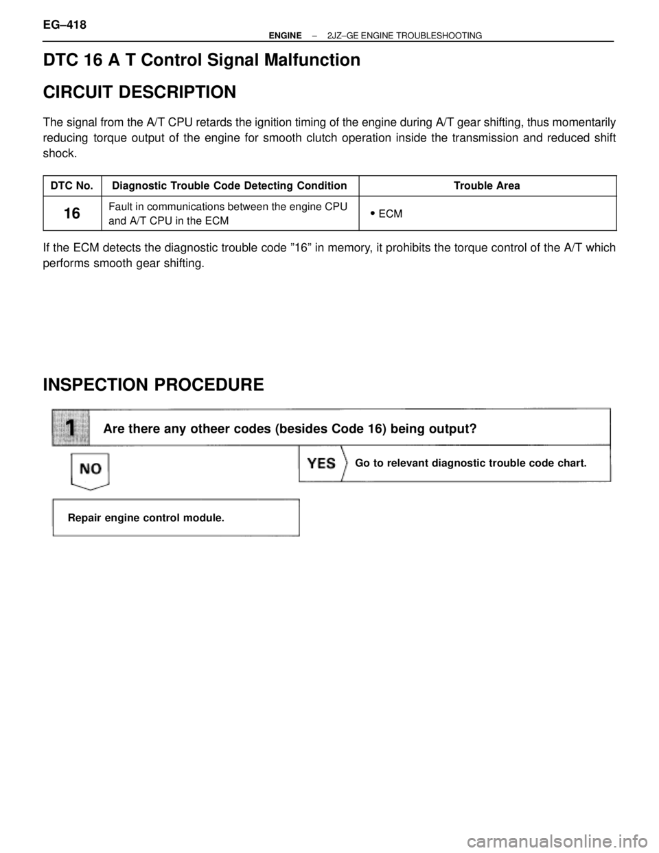
DTC 16 A T Control Signal Malfunction
CIRCUIT DESCRIPTION
The signal from the A/T CPU retards the ignition timing of the engine during A/T gear shifting, thus momentarily
reducing torque output of the engine for smooth clutch operation inside the transmission and reduced shift
shock.
����� �����DTC No.���������������� ����������������Diagnostic Trouble Code Detecting Condition����������������� �����������������Trouble Area����� �����
16
���������������� ����������������
Fault in communications between the engine CPU
����������������� �����������������
�ECM����� �����16���������������� ����������������Fault in communications between the engine CPU
and A/T CPU in the ECM����������������� ������������������ ECM
If the ECM detects the diagnostic trouble code º16º in memory, it prohibits the torque control of the A/T which
performs smooth gear shifting.
INSPECTION PROCEDURE
Are there any otheer codes (besides Code 16) being output?
Repair engine control module.
Go to relevant diagnostic trouble code chart.
EG±418± ENGINE2JZ±GE ENGINE TROUBLESHOOTING
Page 181 of 878
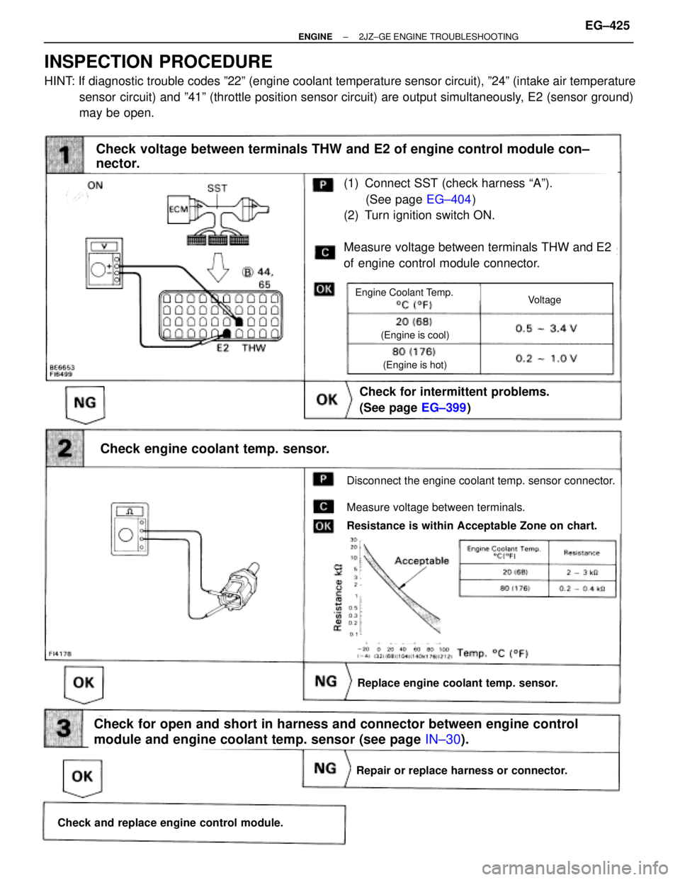
(See page EG±404)
(1) Connect SST (check harness ªAº).
(See page EG±404)
(2) Turn ignition switch ON.
Measure voltage between terminals THW and E2
of engine control module connector.
Check for intermittent problems.
(See page EG±399)
Check engine coolant temp. sensor.
Replace engine coolant temp. sensor.
Repair or replace harness or connector.
Check and replace engine control module.
Check for open and short in harness and connector between engine control
module and engine coolant temp. sensor (see page IN±30).
Disconnect the engine coolant temp. sensor connector.
Measure voltage between terminals.
Resistance is within Acceptable Zone on chart.
Check voltage between terminals THW and E2 of engine control module con±
nector.
VoltageEngine Coolant Temp.
(Engine is cool)
(Engine is hot)
INSPECTION PROCEDURE
HINT: If diagnostic trouble codes º22º (engine coolant temperature sensor circuit), º24º (intake air temperature
sensor circuit) and º41º (throttle position sensor circuit) are output simultaneously, E2 (sensor ground)
may be open.
± ENGINE2JZ±GE ENGINE TROUBLESHOOTINGEG±425
Page 183 of 878
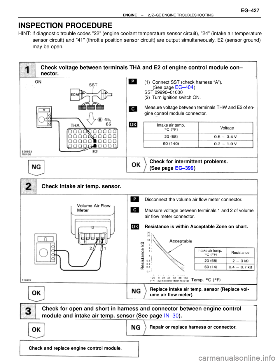
(See page EG±404)
(1) Connect SST (check harness ªAº).
(See page
EG±404)
SST 09990±01000
(2) Turn ignition switch ON.
Measure voltage between terminals THW and E2 of en-
gine control module connector.
Check for intermittent problems.
(See page EG±399)
Check intake air temp. sensor.
Disconnect the volume air flow meter connector.
Measure voltage between terminals 1 and 2 of volume
air flow meter connector.
Resistance is within Acceptable Zone on chart.
Check voltage between terminals THA and E2 of engine control module con±
nector.
Replace intake air temp. sensor (Replace vol-
ume air flow meter).
Check for open and short in harness and connector between engine control
module and intake air temp. sensor (See page IN±30).
Repair or replace harness or connector.
Check and replace engine control module.
VoltageIntake air temp.
ResistanceIntake air temp.
INSPECTION PROCEDURE
HINT: If diagnostic trouble codes º22º (engine coolant temperature sensor circuit), º24º (intake air temperature
sensor circuit) and º41º (throttle position sensor circuit) are output simultaneously, E2 (sensor ground)
may be open.
± ENGINE2JZ±GE ENGINE TROUBLESHOOTINGEG±427
Page 184 of 878
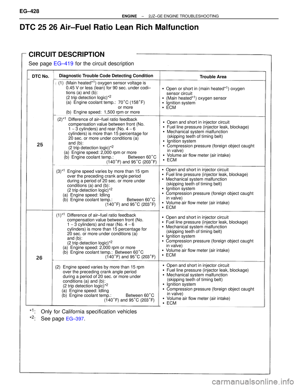
CIRCUIT DESCRIPTION
See page EG±419 for the circuit description
DTC No.Diagnostic Trouble Code Detecting ConditionTrouble Area
(1) (Main heated*1) oxygen sensor voltage is
0.45 V or less (lean) for 90 sec. under codi±
tions (a) and (b):
(2 trip detection logic)*
2
(a) Engine coolant temp.: 70°C (158°F)
or more
(b) Engine speed: 1,500 rpm or more
(2)*1Difference of air±fuel ratio feedback
compensation value between front (No.
1 ~ 3 cylinders) and rear (No. 4 ~ 6
cylinders) is more than 15 percentage for
20 sec. or more under conditions (a)
and (b):
(2 trip detection logic)*
2
(a) Engine speed: 2,000 rpm or more
(b) Engine coolant temp.: Between 60°C
(140°F) and 95°C (203°F)
(1)*1Difference of air±fuel ratio feedback
compensation value between front (No.
1 ~ 3 cylinders) and rear (No. 4 ~ 6
cylinders) is more than 15 percentage for
20 sec. or more under conditions (a)
and (b):
(2 trip detection logic)*
2
(a) Engine speed: 2,000 rpm or more
(b) Engine coolant temp.: Between 60°C
(140°F) and 95°C (203°F)
(3)*1Engine speed varies by more than 15 rpm
over the preceding crank angle period
during a period of 20 sec. or more under
conditions (a) and (b):
(2 trip detection logic)*
2
(a) Engine speed: Idling
(b) Engine coolant temp.: Between 60°C
(140°F) and 95°C (203°F)
(2) Engine speed varies by more than 15 rpm
over the preceding crank angle period
during a period of 20 sec. or more under
conditions (a) and (b):
(2 trip detection logic)*
2
(a) Engine speed: Idling
(b) Engine coolant temp.: Between 60°C
(140°F) and 95°C (203°F)
*1: Only for California specification vehicles
*
2: See page EG±397.
�Open or short in (main heated*1) oxygen
sensor circuit
�(Main heated*
1) oxygen sensor
�Ignition system
�ECM
�Open and short in injector circuit
�Fuel line pressure (injector leak, blockage)
�Mechanical system malfunction
(skipping teeth of timing belt)
�Ignition system
�Compression pressure (foreign object caught
in valve)
�Volume air flow meter (air intake)
�ECM
�Open and short in injector circuit
�Fuel line pressure (injector leak, blockage)
�Mechanical system malfunction
(skipping teeth of timing belt)
�Ignition system
�Compression pressure (foreign object caught
in valve)
�Volume air flow meter (air intake)
�ECM
�Open and short in injector circuit
�Fuel line pressure (injector leak, blockage)
�Mechanical system malfunction
(skipping teeth of timing belt)
�Ignition system
�Compression pressure (foreign object caught
in valve)
�Volume air flow meter (air intake)
�ECM
�Open and short in injector circuit
�Fuel line pressure (injector leak, blockage)
�Mechanical system malfunction
(skipping teeth of timing belt)
�Ignition system
�Compression pressure (foreign object caught
in valve)
�Volume air flow meter (air intake)
�ECM
DTC 25 26 Air±Fuel Ratio Lean Rich Malfunction
EG±428± ENGINE2JZ±GE ENGINE TROUBLESHOOTING
Page 192 of 878
(See page EG±404)
INSPECTION PROCEDURE
HINT: When other codes are output in addition to 27 at the same time, check the circuits for other codes
first.
Check voltage between terminal HT3 of engine control module connector and
body ground.
(1) Connect SST (check harness ªAº).
(See page EG±404)
SST 09990±01000
(2) Turn ignition switch ON.
Measure voltage between terminal HT3 of engine
control module connector and body ground.
Voltage: 9 Ð 14 V EG±436
± ENGINE2JZ±GE ENGINE TROUBLESHOOTING
Page 194 of 878
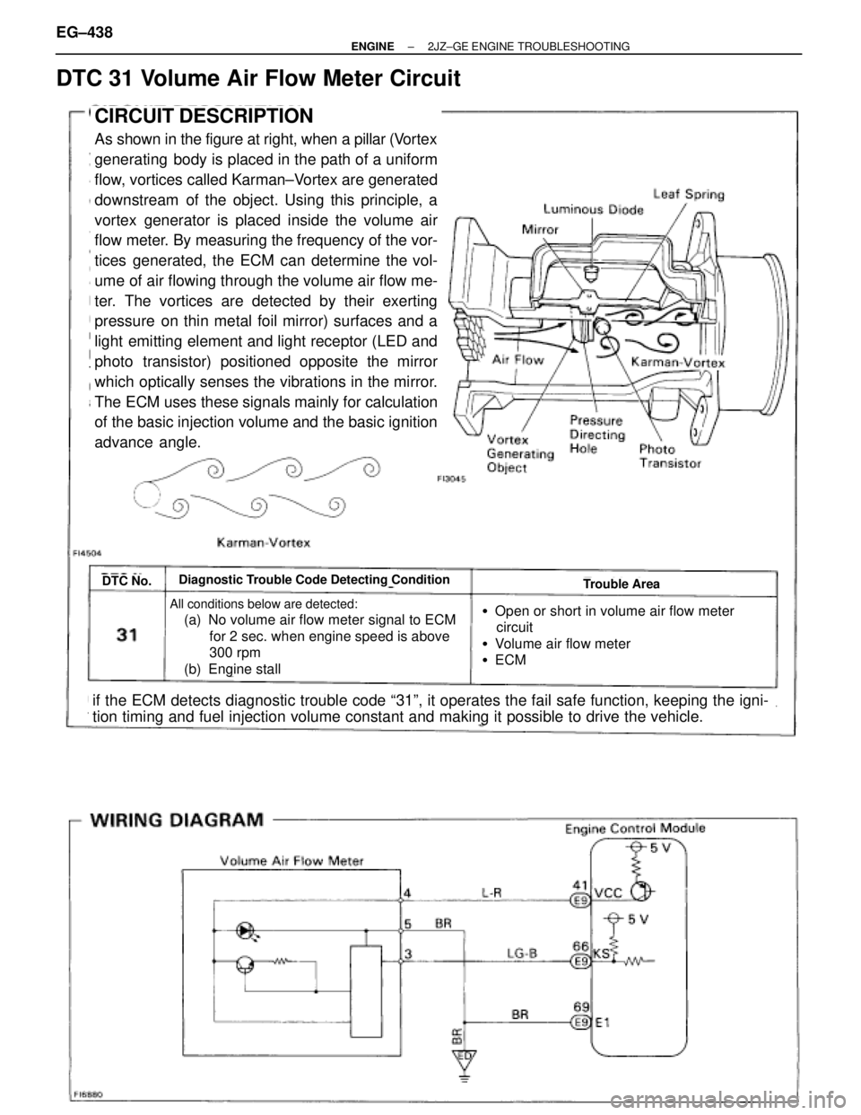
DTC 31 Volume Air Flow Meter Circuit
CIRCUIT DESCRIPTION
As shown in the figure at right, when a pillar (Vortex
generating body is placed in the path of a uniform
flow, vortices called Karman±Vortex are generated
downstream of the object. Using this principle, a
vortex generator is placed inside the volume air
flow meter. By measuring the frequency of the vor-
tices generated, the ECM can determine the vol-
ume of air flowing through the volume air flow me-
ter. The vortices are detected by their exerting
pressure on thin metal foil mirror) surfaces and a
light emitting element and light receptor (LED and
photo transistor) positioned opposite the mirror
which optically senses the vibrations in the mirror.
The ECM uses these signals mainly for calculation
of the basic injection volume and the basic ignition
advance angle.
DTC No.Diagnostic Trouble Code Detecting ConditionTrouble Area
All conditions below are detected:
(a) No volume air flow meter signal to ECM
for 2 sec. when engine speed is above
300 rpm
(b) Engine stall �Open or short in volume air flow meter
circuit
�Volume air flow meter
�ECM
if the ECM detects diagnostic trouble code ª31º, it operates the fail safe function, keeping the igni-
tion timing and fuel injection volume constant and making it possible to drive the vehicle. EG±438
± ENGINE2JZ±GE ENGINE TROUBLESHOOTING
Page 196 of 878
Disconnect volume air flow meter connector and check voltage between
terminals KS and E1 of engine control module connector.
(1) Disconnect the volume air flow meter connec±
tor.
(2) Turn ignition switch ON.
Measure voltage between terminals KS and E1 of
engine control module connector.
Voltage: 4.5 Ð 5.5 V
(1) Disconnect the volume air flow meter connec±
tor.
(2) Turn ignition switch ON.
Measure voltage between terminals VCC and E1
of engine control module connector.
Voltage: 4.5 Ð 5.5 V
Disconnect volume air flow meter connector and check voltage between
terminals VCC and E1 of engine control module connector.
Check and replace engine control module.
Replace volume air flow meter.
Check and replace engine control module.
EG±440± ENGINE2JZ±GE ENGINE TROUBLESHOOTING