Page 249 of 878
(g) Reconnect the negative (±) terminal cable to the battery.
(h) Turn the ignition switch ON.
(i) Measure the fuel pressure.
Fuel pressure:
226±275 kPa (2.3±2.8 kgf/cm
2, 33±40 psi)
If pressure is high, replace the fuel pressure regulator.
If pressure is low, check the following parts:
wFuel hoses and connections
wFuel pump
wFuel filter
wFuel pressure regulator
(j) Remove the SST from the DLC1.
SST 09843±18020
(k) Start the engine.
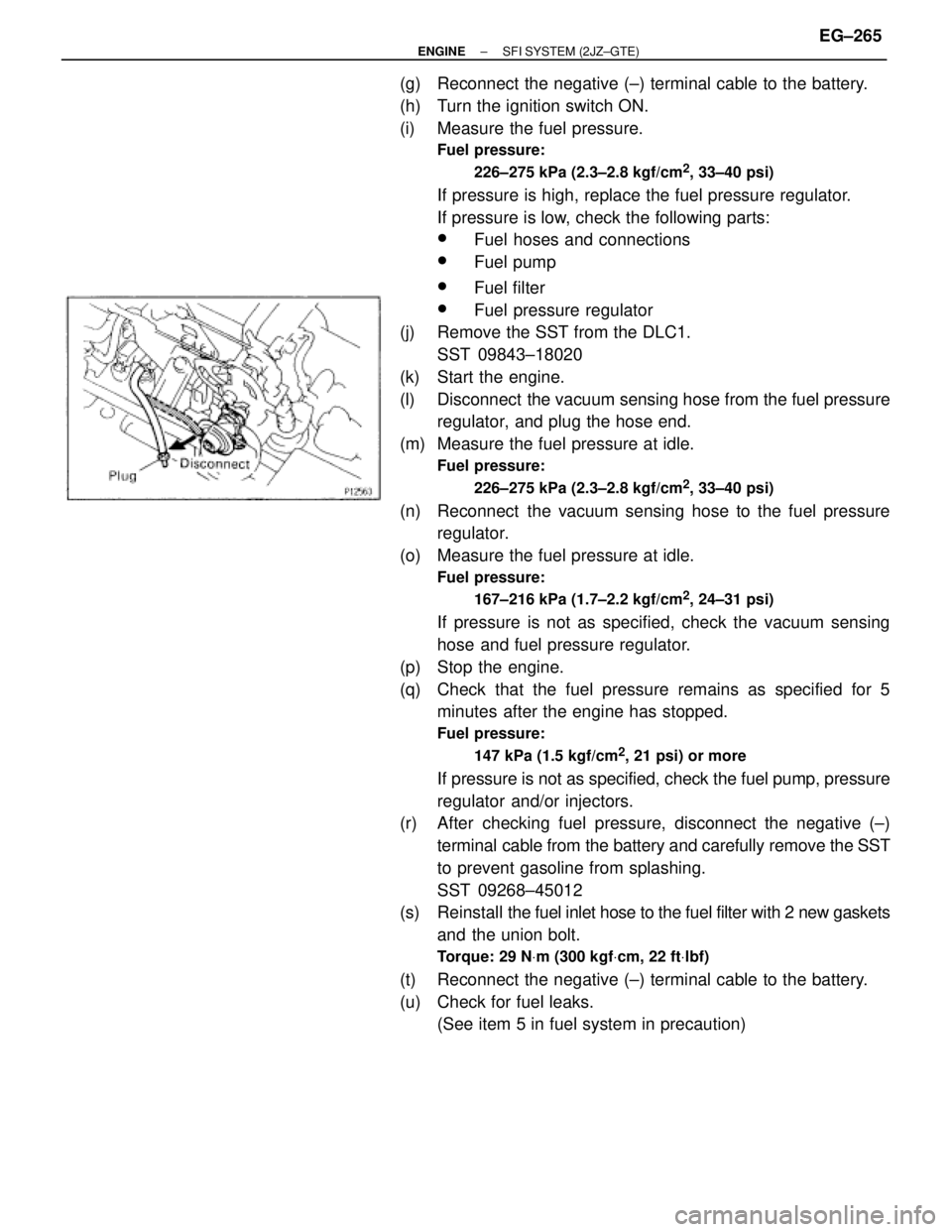
(l) Disconnect the vacuum sensing hose from the fuel pressure
regulator, and plug the hose end.
(m) Measure the fuel pressure at idle.
Fuel pressure:
226±275 kPa (2.3±2.8 kgf/cm
2, 33±40 psi)
(n) Reconnect the vacuum sensing hose to the fuel pressure
regulator.
(o) Measure the fuel pressure at idle.
Fuel pressure:
167±216 kPa (1.7±2.2 kgf/cm
2, 24±31 psi)
If pressure is not as specified, check the vacuum sensing
hose and fuel pressure regulator.
(p) Stop the engine.
(q) Check that the fuel pressure remains as specified for 5
minutes after the engine has stopped.
Fuel pressure:
147 kPa (1.5 kgf/cm
2, 21 psi) or more
If pressure is not as specified, check the fuel pump, pressure
regulator and/or injectors.
(r) After checking fuel pressure, disconnect the negative (±)
terminal cable from the battery and carefully remove the SST
to prevent gasoline from splashing.
SST 09268±45012
(s) Reinstall the fuel inlet hose to the fuel filter with 2 new gaskets
and the union bolt.
Torque: 29 NVm (300 kgfVcm, 22 ftVlbf)
(t) Reconnect the negative (±) terminal cable to the battery.
(u) Check for fuel leaks.
(See item 5 in fuel system in precaution)
± ENGINESFI SYSTEM (2JZ±GTE)EG±265
Page 265 of 878
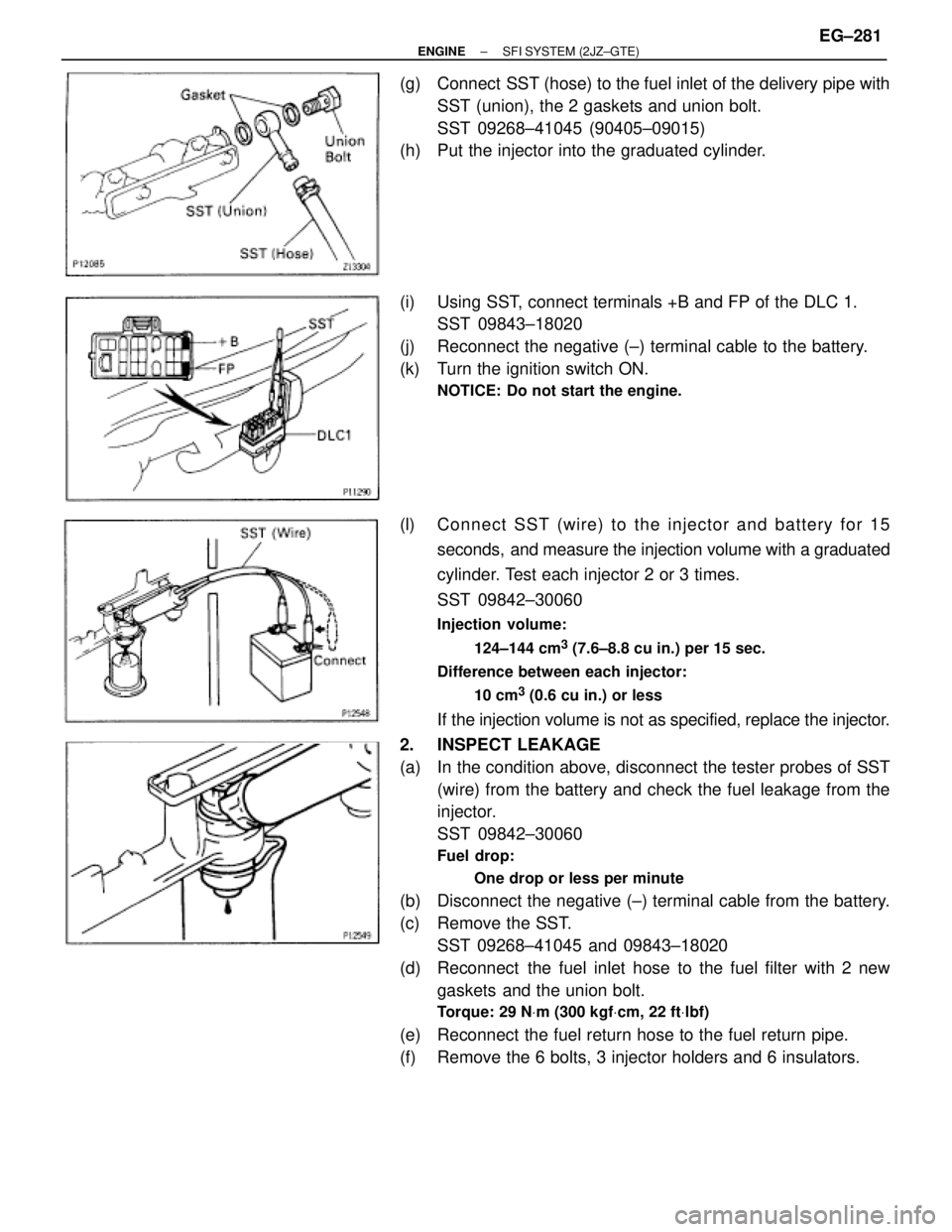
(g) Connect SST (hose) to the fuel inlet of the delivery pipe with
SST (union), the 2 gaskets and union bolt.
SST 09268±41045 (90405±09015)
(h) Put the injector into the graduated cylinder.
(i) Using SST, connect terminals +B and FP of the DLC 1.
SST 09843±18020
(j) Reconnect the negative (±) terminal cable to the battery.
(k) Turn the ignition switch ON.
NOTICE: Do not start the engine.
(l) Connect SST (wire) to the injector and battery for 15
seconds, and measure the injection volume with a graduated
cylinder. Test each injector 2 or 3 times.
SST 09842±30060
Injection volume:
124±144 cm
3 (7.6±8.8 cu in.) per 15 sec.
Difference between each injector:
10 cm
3 (0.6 cu in.) or less
If the injection volume is not as specified, replace the injector.
2. INSPECT LEAKAGE
(a) In the condition above, disconnect the tester probes of SST
(wire) from the battery and check the fuel leakage from the
injector.
SST 09842±30060
Fuel drop:
One drop or less per minute
(b) Disconnect the negative (±) terminal cable from the battery.
(c) Remove the SST.
SST 09268±41045 and 09843±18020
(d) Reconnect the fuel inlet hose to the fuel filter with 2 new
gaskets and the union bolt.
Torque: 29 NVm (300 kgfVcm, 22 ftVlbf)
(e) Reconnect the fuel return hose to the fuel return pipe.
(f) Remove the 6 bolts, 3 injector holders and 6 insulators.
± ENGINESFI SYSTEM (2JZ±GTE)EG±281
Page 272 of 878
MAF METER INSPECTION
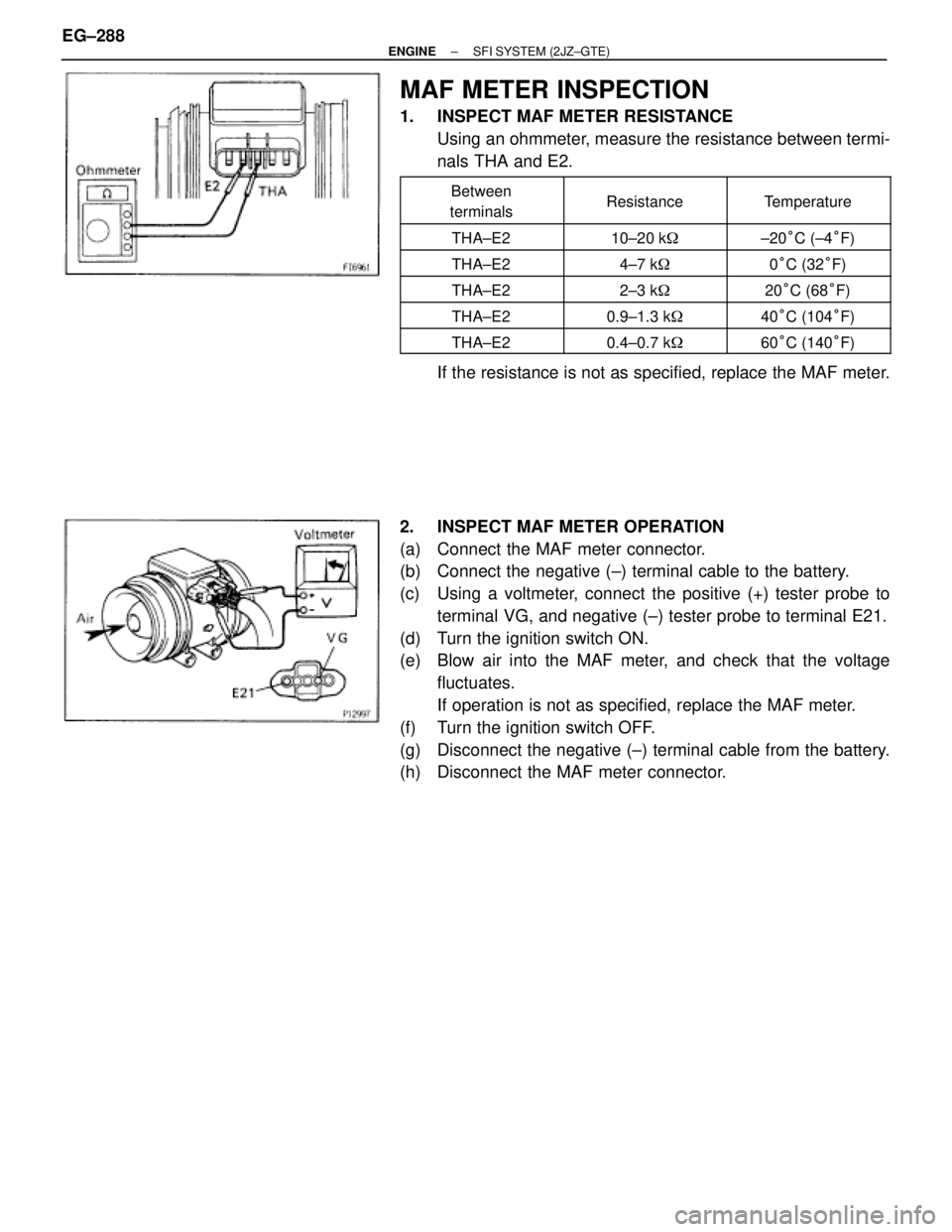
1. INSPECT MAF METER RESISTANCE
Using an ohmmeter, measure the resistance between termi-
nals THA and E2.
�������� �
������� ��������
Between
terminals�������� �
������� ��������Resistance
�������� �
������� ��������Temperature
�������� ��������THA±E2�������� ��������10±20 k��������� ��������±20°C (±4°F)
�������� ��������THA±E2�������� ��������4±7 k��������� ��������0°C (32°F)
�������� ��������THA±E2�������� ��������2±3 k��������� ��������20°C (68°F)�������� ��������THA±E2�������� ��������0.9±1.3 k��������� ��������40°C (104°F)�������� ��������THA±E2�������� ��������0.4±0.7 k��������� ��������60°C (140°F)
If the resistance is not as specified, replace the MAF meter.
2. INSPECT MAF METER OPERATION
(a) Connect the MAF meter connector.
(b) Connect the negative (±) terminal cable to the battery.
(c) Using a voltmeter, connect the positive (+) tester probe to
terminal VG, and negative (±) tester probe to terminal E21.
(d) Turn the ignition switch ON.
(e) Blow air into the MAF meter, and check that the voltage
fluctuates.
If operation is not as specified, replace the MAF meter.
(f) Turn the ignition switch OFF.
(g) Disconnect the negative (±) terminal cable from the battery.
(h) Disconnect the MAF meter connector. EG±288
± ENGINESFI SYSTEM (2JZ±GTE)
Page 298 of 878
TURBO PRESSURE SENSOR
COMPONENTS FOR REMOVAL AND
INSTALLATION
TURBO PRESSURE SENSOR
INSPECTION
1. INSPECT POWER SOURCE VOLTAGE OF TURBO
PRESSURE SENSOR
(a) Disconnect the turbo pressure sensor connector.
(b) Turn the ignition switch ON.
(c) Using a voltmeter, measure the voltage between connector
terminals VC and E2 of the wiring harness side.
Voltage:
4.5±5.5 V
(d) Turn the ignition switch OFF.
(e) Reconnect the turbo pressure sensor connector. EG±314
± ENGINESFI SYSTEM (2JZ±GTE)
Page 299 of 878
2. INSPECT SUPPLY POWER OF TURBO PRESSURE
SENSOR
(a) Disconnect the ECM from the ECU bracket.
(See steps 1 to 4 in ECM)
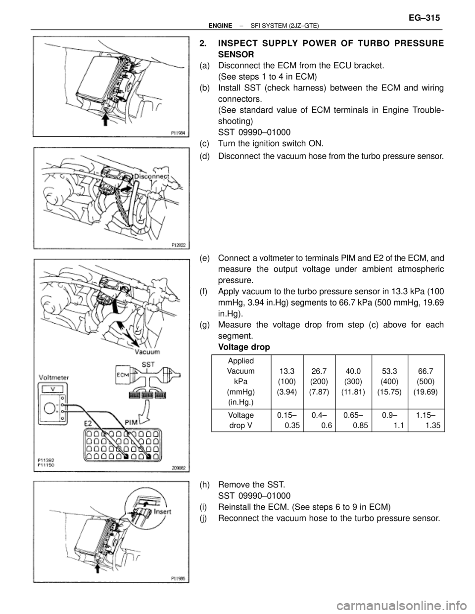
(b) Install SST (check harness) between the ECM and wiring
connectors.
(See standard value of ECM terminals in Engine Trouble-
shooting)
SST 09990±01000
(c) Turn the ignition switch ON.
(d) Disconnect the vacuum hose from the turbo pressure sensor.
(e) Connect a voltmeter to terminals PIM and E2 of the ECM, and
measure the output voltage under ambient atmospheric
pressure.
(f) Apply vacuum to the turbo pressure sensor in 13.3 kPa (100
mmHg, 3.94 in.Hg) segments to 66.7 kPa (500 mmHg, 19.69
in.Hg).
(g) Measure the voltage drop from step (c) above for each
segment.
Voltage drop
������ �
����� �
����� �
����� �
����� ������
Applied
Vacuum
kPa
(mmHg)
(in.Hg.)���� �
��� �
��� �
��� �
��� ����
13.3
(100)
(3.94)
���� �
��� �
��� �
��� �
��� ����
26.7
(200)
(7.87)
���� �
��� �
��� �
��� �
��� ����
40.0
(300)
(11.81)
���� �
��� �
��� �
��� �
��� ����
53.3
(400)
(15.75)
���� �
��� �
��� �
��� �
��� ����
66.7
(500)
(19.69)
������ �
����� ������
Voltage
drop V���� �
��� ����
0.15±
0.35���� �
��� ����
0.4±
0.6���� �
��� ����
0.65±
0.85���� �
��� ����
0.9±
1.1���� �
��� ����
1.15±
1.35
(h) Remove the SST.
SST 09990±01000
(i) Reinstall the ECM. (See steps 6 to 9 in ECM)
(j) Reconnect the vacuum hose to the turbo pressure sensor.
± ENGINESFI SYSTEM (2JZ±GTE)EG±315
Page 310 of 878
FUEL CUT RPM
FUEL CUT RPM INSPECTION
1. WARM UP ENGINE
Allow the engine to warm up to normal operating tempera-
ture.
2. CONNECT TACHOMETER TO ENGINE
Connect the tester probe of a tachometer to terminal IG� of
the DLC1.
NOTICE:
wNever allow the tachometer terminal to touch ground as
it could result in damage to the igniter and/or ignition
coil.
wAs some tachometers are not compatible with this igni-
tion system, we recommend that you confirm the compat-
ibility of your unit before use.
3. INSPECT FUEL CUTOFF OPERATION
(a) Increase the engine speed to at least 3,000 rpm.
(b) Check for injector operating noise.
(c) Check that when the throttle lever is released, injector
operation noise stops momentarily and then resumes.
HINT: Measure with the A/C OFF.
Fuel return speed:
1,400 rpm
(Vehicle speed less than 25 km/h (16mph), with
brake OFF)
4. DISCONNECT TACHOMETER EG±326
± ENGINESFI SYSTEM (2JZ±GTE)
Page 315 of 878
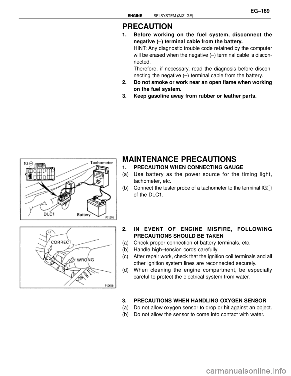
PRECAUTION
1. Before working on the fuel system, disconnect the
negative (±) terminal cable from the battery.
HINT: Any diagnostic trouble code retained by the computer
will be erased when the negative (±) terminal cable is discon-
nected.
Therefore, if necessary, read the diagnosis before discon-
necting the negative (±) terminal cable from the battery.
2. Do not smoke or work near an open flame when working
on the fuel system.
3. Keep gasoline away from rubber or leather parts.
MAINTENANCE PRECAUTIONS
1. PRECAUTION WHEN CONNECTING GAUGE
(a) Use ba tte ry as th e po we r so u rce fo r th e timin g lig h t,
tachometer, etc.
(b) Connect the tester probe of a tachometer to the terminal IG�
of the DLC1.
2. IN EVENT OF ENGINE MISFIRE, FOLLOWING
PRECAUTIONS SHOULD BE TAKEN
(a) Check proper connection of battery terminals, etc.
(b) Handle high±tension cords carefully.
(c) After repair work, check that the ignition coil terminals and all
other ignition system lines are reconnected securely.
(d) When cleaning the engine compartment, be especially
careful to protect the electrical system from water.
3. PRECAUTIONS WHEN HANDLING OXYGEN SENSOR
(a) Do not allow oxygen sensor to drop or hit against an object.
(b) Do not allow the sensor to come into contact with water.
± ENGINESFI SYSTEM (2JZ±GE)EG±189
Page 316 of 878

IF VEHICLE IS EQUIPPED WITH MOBIL
RADIO SYSTEM (HAM, CB, ETC.)
If the vehicle is equipped with a mobile communication sys-
tem, refer to the precaution in the IN section.
AIR INDUCTION SYSTEM
1. Separation of the engine oil dipstick, oil filler cap, PCV hose,
etc. may cause the engine to run out of tune.
2. Disconnection, looseness or cracks in the parts of the air
induction system between the throttle body and cylinder
head will cause air suction and cause the engine to run out
of tune.
ELECTRONIC CONTROL SYSTEM
1. Before removing SFI wiring connectors, terminals, etc., first
disconnect the power by either turning the ignition switch
OFF or disconnecting the negative (±) terminal cable from the
battery.
HINT: Always check the diagnostic trouble code before dis-
connecting the negative (±) terminal cable from the battery.
2. When installing the battery, be especially careful not to
incorrectly connect the positive (+) and negative (±) cables.
3. Do not permit parts to receive a severe impact during removal
or installation. Handle all SFI parts carefully, especially the
ECM.
4. Do not be careless during troubleshooting as there are
numerous transistor circuits and even slight terminal contact
can cause further troubles.
5. Do not open the ECM cover.
6. When inspecting during rainy weather, take care to prevent
entry of water. Also, when washing the engine compartment,
prevent water from getting on the SFI parts and wiring
connectors.
7. Parts should be replaced as an assembly.
8. Care is required when pulling out and inserting wiring
connectors.
(a) Release the lock and pull out the connector, pulling on the
connectors.
(b) Fully insert the connector and check that it is locked. EG±190
± ENGINESFI SYSTEMS (2JZ±GE)