Page 1876 of 2389
![TOYOTA CAMRY V20 1986 Service Information TEST METHOD B (High Speed Test)
[Vehicle speed: Over 38 mph (60 km/h)]
1. SET CENTER DIFFERENTIAL CONTROL SWITCH TO
OFF
(1) Check that the center differential control indicator light
goes oft.
(2) Fur TOYOTA CAMRY V20 1986 Service Information TEST METHOD B (High Speed Test)
[Vehicle speed: Over 38 mph (60 km/h)]
1. SET CENTER DIFFERENTIAL CONTROL SWITCH TO
OFF
(1) Check that the center differential control indicator light
goes oft.
(2) Fur](/manual-img/14/57449/w960_57449-1875.png)
TEST METHOD B (High Speed Test)
[Vehicle speed: Over 38 mph (60 km/h)]
1. SET CENTER DIFFERENTIAL CONTROL SWITCH TO
OFF
(1) Check that the center differential control indicator light
goes oft.
(2) Further check that the operation of the hydraulic multi-
plate clutch control of the center differential is in
OFF condition.
(See page IN±15)
2. MOVE MODE SELECT LEVER ON TRANSAXLE TO ºLOCKº
MODE AND LOCK IT SECURELY WITH BOLT
(See page IN±16)
3. CONFIRM MODE SELECTION
(See page IN±17) 7. OPERATE TESTER ROLLERS AND MEASURE
BRAKING FORCE WITH ENGINE AT IDLE
HINT: Since different types of tester are used, such as spe-
cialized brake testers and combination testers with built in
chassis dynamometer, speedometer tester, brake tester, etc.,
conduct the test in accordance with the instructions furnished
for the tester model used.
4. REMOVE REAR PROPELLER SHAFT
Make matching marks on each end of the propeller shaft,
then remove it.8. AFTER FINISHING TEST, RETURN CENTER
DIFFERENTIAL CONTROL SWITCH TO ºAUTOº AND
CHECK THAT INDICATOR LIGHT GOES ON
± INTRODUCTIONPrecautions When Servicing Full±Time 4WD VehiclesIN±19
Page 1878 of 2389
![TOYOTA CAMRY V20 1986 Service Information SPEEDOMETER TEST OR OTHER TESTS
[Using Speedometer Tester or Chassis Dynamometer]
1. SET CENTER DIFFERENTIAL CONTROL SWITCH TO
OFF
(1) Check that the center differential control indicator light
goes TOYOTA CAMRY V20 1986 Service Information SPEEDOMETER TEST OR OTHER TESTS
[Using Speedometer Tester or Chassis Dynamometer]
1. SET CENTER DIFFERENTIAL CONTROL SWITCH TO
OFF
(1) Check that the center differential control indicator light
goes](/manual-img/14/57449/w960_57449-1877.png)
SPEEDOMETER TEST OR OTHER TESTS
[Using Speedometer Tester or Chassis Dynamometer]
1. SET CENTER DIFFERENTIAL CONTROL SWITCH TO
OFF
(1) Check that the center differential control indicator light
goes oft.
(2) Further check that the operation of the hydraulic
multiplate clutch control of the center differential is in
OFF condition.
(See page IN±15)
2. MOVE MODE SELECT LEVER ON TRANSAXLE TO ºLOCKº
MODE AND LOCK IT SECURELY WITH BOLT (See page
IN±16)
3. CONFIRM MODE SELECTION
(See page IN±17)
8. DISCONNECT INERTIA WEIGHT FROM TESTER ROLL-
ER (If equipped with it)
9. TEST VEHICLE
(1) Start the engine.
(2) Put the transmission in D range, then gradually in-
crease the speed as the test in conducted.
(3) After the test is finished, reduce the speed gradually
and stop the engine. 4. REMOVE REAR PROPELLER SHAFT
Make matching marks on each end of the rear propeller
shaft, then remove it.
5. PLACE FRONT WHEELS ON TESTER ROLLERS
6. CHOCK REAR WHEELS
7. APPLY PARKING BRAKE
10. AFTER FINISHING TEST, INSTALL REAR PROPELLER
SHAFT
Align the matching marks made on the rear propeller shaft
before removal, then install it.
± INTRODUCTIONPrecautions When Servicing Full±Time 4WD VehiclesIN±21
Page 1880 of 2389

ON±VEHICLE WHEEL BALANCING
NOTICE:
1. When doing on±vehicle wheel balancing on a fulltime 4WD
vehicle, to prevent the wheels from rotating at different
speeds or in different directions from each other (which
could lead to damage to the center differential or trans-
axle gears), always be sure to observe the following pre-
cautions:
(1) A11 four wheels should be jacked up, completely clear
of the ground.
(2) The wheels should be driven by both the engine and
the wheel balancer.
(3) The center differential control switch should be in the
OFF condition.
(4) The mode select lever on the transaxle should be in
the LOCK position.
(5) The parking brake lever should be fully released.
(6) None of the brakes should be allowed to drag.
2. Avoid sudden acceleration, deceleration and braking.
3. Carry out the wheel balancing with the transmission in D
range.
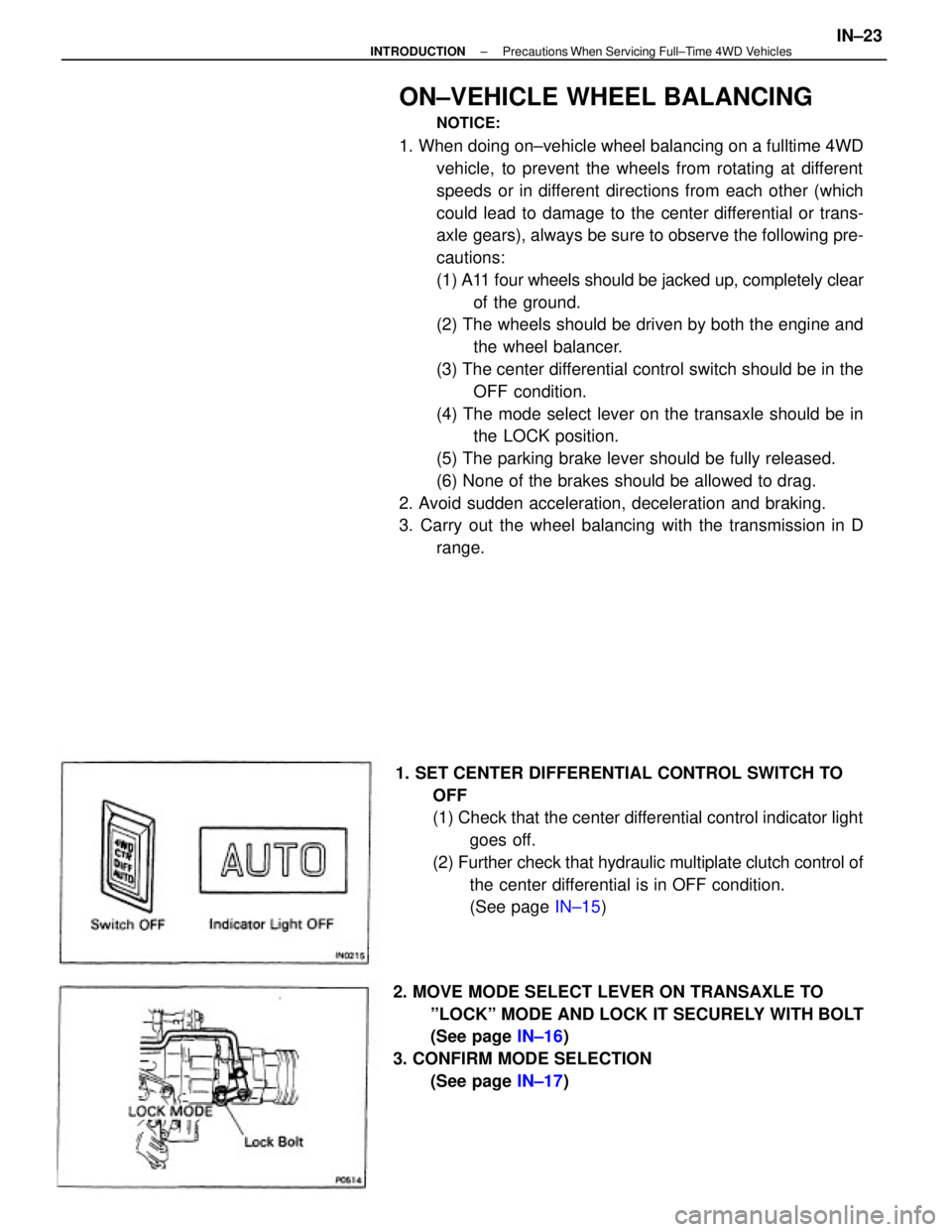
1. SET CENTER DIFFERENTIAL CONTROL SWITCH TO
OFF
(1) Check that the center differential control indicator light
goes off.
(2) Further check that hydraulic multiplate clutch control of
the center differential is in OFF condition.
(See page IN±15)
2. MOVE MODE SELECT LEVER ON TRANSAXLE TO
ºLOCKº MODE AND LOCK IT SECURELY WITH BOLT
(See page IN±16)
3. CONFIRM MODE SELECTION
(See page IN±17)
± INTRODUCTIONPrecautions When Servicing Full±Time 4WD VehiclesIN±23
Page 1885 of 2389

ABBREVIATIONS USED IN THIS
MANUAL
A.B.S. Anti±Lock Brake System
A/C Air Conditioner
ALR Automatic Locking Retractor
Approx. Approximation
A/T, ATM Automatic Transaxle
ATF Automatic Transmission Fluid
B
0 Overdrive Brake
B
1 Second Coast Brake
B
2 Second Brake
B
3 First and Reverse Brake
BDC Bottom Dead Center
BTDC Before Top Dead Center
BVSV Bimetal Vacuum Switching Valve
C
0 Overdrive Clutch
C
1 Forward Clutch
C
2 Direct Clutch
CB Circuit Breaker
DP Dash Pot
CRS Child Restraint System
ECT Electronic Controlled Transaxle
ECU Electronic Controlled Unit
EFI Electronic Fuel Injection
E/G Engine
EGR Exhaust Gas Recirculation
ELR Emergency Locking Retractor
ESA Electronic Spark Advance
EVAP Evaporative (Emission Control)
EX Exhaust (manifold, valve)
Ex. Except
F
0 Overdrive One±Way Clutch
F
1 No. 1 One±Way Clutch
F
2 No. 2 One±Way Clutch
FIPG Formed in Place Gasket
FL Fusible Link
Fr Front
IG Ignition
IN Intake (manifold, valve)
ISC Idle Speed Control
LED Light Emitting Diode
LH Left±Hand
LSPV Load Sensing Proportioning Valve
Max. Maximum
Min. Minimum
MP Multipurpose
M/T, MTM Manual Transaxle
O/D, OD Overdrive
O/S Oversize
PCV Positive Crankcase Ventilation
PKB Parking Brake
± INTRODUCTIONAbbreviations Used in This ManualIN±28
Page 1919 of 2389

BRAKES
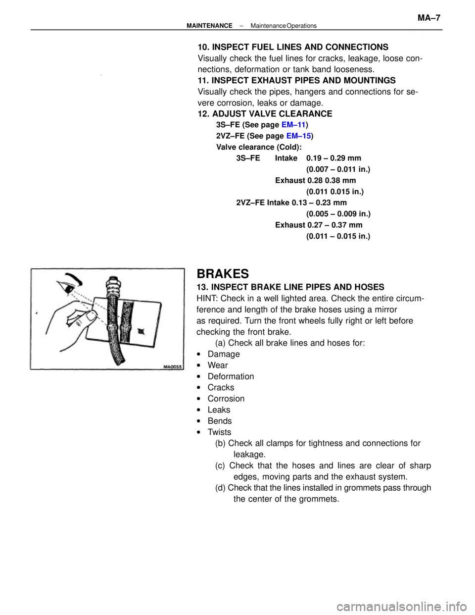
13. INSPECT BRAKE LINE PIPES AND HOSES
HINT: Check in a well lighted area. Check the entire circum-
ference and length of the brake hoses using a mirror
as required. Turn the front wheels fully right or left before
checking the front brake.
(a) Check all brake lines and hoses for:
wDamage
wWear
wDeformation
wCracks
wCorrosion
wLeaks
wBends
wTwists
(b) Check all clamps for tightness and connections for
leakage.
(c) Check that the hoses and lines are clear of sharp
edges, moving parts and the exhaust system.
(d) Check that the lines installed in grommets pass through
the center of the grommets. 10. INSPECT FUEL LINES AND CONNECTIONS
Visually check the fuel lines for cracks, leakage, loose con-
nections, deformation or tank band looseness.
11. INSPECT EXHAUST PIPES AND MOUNTINGS
Visually check the pipes, hangers and connections for se-
vere corrosion, leaks or damage.
12. ADJUST VALVE CLEARANCE
3S±FE (See page EM±11)
2VZ±FE (See page EM±15)
Valve clearance (Cold):
3S±FE Intake 0.19 ± 0.29 mm
(0.007 ± 0.011 in.)
Exhaust 0.28 0.38 mm
(0.011 0.015 in.)
2VZ±FE Intake 0.13 ± 0.23 mm
(0.005 ± 0.009 in.)
Exhaust 0.27 ± 0.37 mm
(0.011 ± 0.015 in.)
± MAINTENANCEMaintenance OperationsMA±7
Page 1920 of 2389

(d) Settle the parking brake shoes and drum. When per-
forming the road test in item 23, do the following:
wDrive the vehicle at approx. 50 km/h (30 mph) on a safe, lev-
el and dry road.
wWith the parking brake release button pushed in, pull on the
lever with 9 kg (20 Ib, 88 N) of force.
wDrive the vehicle for approx. m (1 /4 mile) in this condition.
wRepeat this procedure 2 or 3 times.
wCheck parking lever travel.
If necessary, adjust the parking brake.
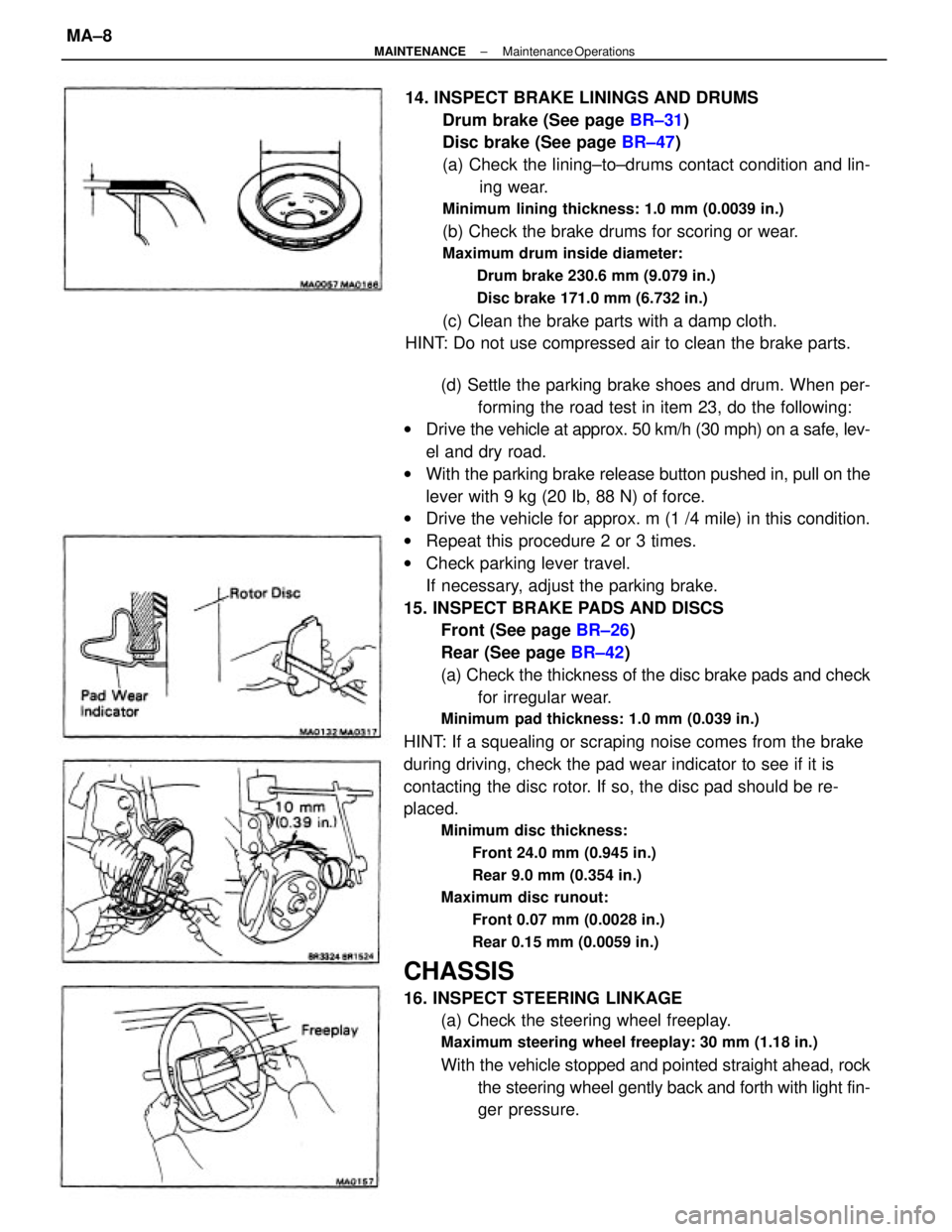
15. INSPECT BRAKE PADS AND DISCS
Front (See page BR±26)
Rear (See page BR±42)
(a) Check the thickness of the disc brake pads and check
for irregular wear.
Minimum pad thickness: 1.0 mm (0.039 in.)
HINT: If a squealing or scraping noise comes from the brake
during driving, check the pad wear indicator to see if it is
contacting the disc rotor. If so, the disc pad should be re-
placed.
Minimum disc thickness:
Front 24.0 mm (0.945 in.)
Rear 9.0 mm (0.354 in.)
Maximum disc runout:
Front 0.07 mm (0.0028 in.)
Rear 0.15 mm (0.0059 in.)
CHASSIS
16. INSPECT STEERING LINKAGE
(a) Check the steering wheel freeplay.
Maximum steering wheel freeplay: 30 mm (1.18 in.)
With the vehicle stopped and pointed straight ahead, rock
the steering wheel gently back and forth with light fin-
ger pressure. 14. INSPECT BRAKE LININGS AND DRUMS
Drum brake (See page BR±31)
Disc brake (See page BR±47)
(a) Check the lining±to±drums contact condition and lin-
ing wear.
Minimum lining thickness: 1.0 mm (0.0039 in.)
(b) Check the brake drums for scoring or wear.
Maximum drum inside diameter:
Drum brake 230.6 mm (9.079 in.)
Disc brake 171.0 mm (6.732 in.)
(c) Clean the brake parts with a damp cloth.
HINT: Do not use compressed air to clean the brake parts.
± MAINTENANCEMaintenance OperationsMA±8
Page 2223 of 2389
HINT
wPerform all voltage and resistance measurements with the ECU connected.
wVerify that the battery voltage is 11 V or above with the ignition switch is ON.
Stop light SW ON (Brake pedal depressed) or defogger
SW ONNo trouble (ºCHECKº engine warning light off) and
engine running
Check connector TE 1 ± E 1 not connected
Specifications (Cont'd)
Check connector TE1 ± E1 connected
*1 W/O ECT *2 W/ EGT *3
A/C
EGR gas temp.
sensor
(CALIF.. only)
Ex. shift position P or N rangeIntake air temp. 205C (685F) Measuring plate fully closed
Coolant temp. 805C (1765F)
Shift position P or N rangeMeasuring plate fully open Throttle valve fully closed
Throttle valve fully closed
Heater blower SW ON Air conditioning ONThrottle valve open
Throttle valve open
Throttle valve open
Cranking or idlingSTD voltage (V)
3,000 rpmEG SW ON
IG SW ON IG SW ONIG SW ONIG SW ON
IG SW ON
Cranking
Terminals
Condition
Voltage
Idling
ECU
± SERVICE SPECIFICATIONSEFI System (3S±FE)A±12
Page 2227 of 2389
HINT:
wPerform all voltage and resistance measurements with the ECU connected.
wVerify that the battery voltage is 11 V or above with the ignition switch is ON.
No trouble (ºCHECKº' engine warning light off) and
engine running
Specifications (Cont'd)
Stop light SW ON (Brake pedal depressed)Check connector TE1 ± E1 not connected
Check connector TE1 ± Et connected
Shift position P or N range
Ex shift position P or N rangeIntake air temp. 205C (685F) Measuring plate fully closed
Coolant temp. 605C (1765F) Measuring plate fully open Throttle valve fully closed
Heater blower SW ON Air conditioning ONThrottle valve open
Throttle valve open
Cranking or idling Heater resistance
STD voltage (V) Oxygen
sensor
IG SW ON
IG SW ONIG SW ON
IG SW ONIG SW ON
IG SW ONCranking Terminals
Condition Voltage
Idling
*1 w/ rpm ECU
± SERVICE SPECIFICATIONSEFI System (2VZ±FE)A±15