Page 1027 of 2389
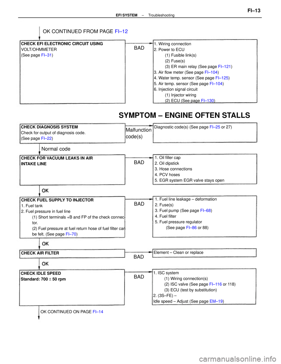
1. Wiring connection
2. Power to ECU
(1) Fusible link(s)
(2) Fuse(s)
(3) ER main relay (See page FI±121)
3. Air flow meter (See page FI±104)
4. Water temp. sensor (See page FI±125)
5. Air temp. sensor (See page FI±104)
6. Injection signal circuit
(1) Injector wiring
(2) ECU (See page FI±130)
CHECK FUEL SUPPLY TO INJECTOR
1. Fuel tank
2. Fuel pressure in fuel line
(1) Short terminals +B and FP of the check connec-
tor.
(2) Fuel pressure at fuel return hose of fuel filter can
be felt. (See page FI±70)
1. ISC system
(1) Wiring connection(s)
(2) ISC valve (See page FI±116 or 118)
(3) ECU (test by substitution)
2. (3S±FE) ±
Idle speed ± Adjust (See page EM±19) 1. Fuel line leakage ± deformation
2. Fuse(s)
3. Fuel pump (See page FI±68)
4. Fuel filter
5. Fuel pressure regulator
(See page FI±86 or 88) 1. Oil filler cap
2. Oil dipstick
3. Hose connections
4. PCV hoses
5. EGR system EGR valve stays open CHECK EFI ELECTRONIC CIRCUIT USING
VOLT/OHMMETER
(See page FI±31)
CHECK DIAGNOSIS SYSTEM
Check for output of diagnosis code.
(See page FI±22)
CHECK FOR VACUUM LEAKS IN AIR
INTAKE LINE
SYMPTOM ± ENGINE OFTEN STALLS
CHECK IDLE SPEED
Standard: 700 + 50 rpmDiagnostic code(s) (See page FI±25 or 27)
OK CONTINUED FROM PAGE FI±12
OK CONTINUED ON PAGE FI±14Element ± Clean or replace
CHECK AIR FILTER
Malfunction
code(s)
Normal code
BADBAD
BAD
BADBAD
± EFI SYSTEMTroubleshootingFI±13
Page 1028 of 2389
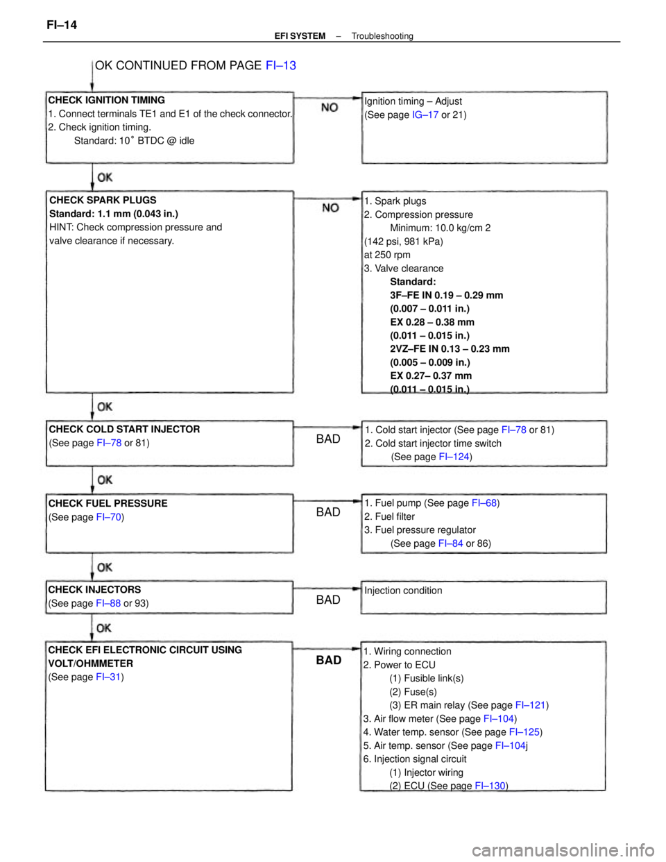
1. Spark plugs
2. Compression pressure
Minimum: 10.0 kg/cm 2
(142 psi, 981 kPa)
at 250 rpm
3. Valve clearance
Standard:
3F±FE IN 0.19 ± 0.29 mm
(0.007 ± 0.011 in.)
EX 0.28 ± 0.38 mm
(0.011 ± 0.015 in.)
2VZ±FE IN 0.13 ± 0.23 mm
(0.005 ± 0.009 in.)
EX 0.27± 0.37 mm
(0.011 ± 0.015 in.)
1. Wiring connection
2. Power to ECU
(1) Fusible link(s)
(2) Fuse(s)
(3) ER main relay (See page FI±121)
3. Air flow meter (See page FI±104)
4. Water temp. sensor (See page FI±125)
5. Air temp. sensor (See page FI±104j
6. Injection signal circuit
(1) Injector wiring
(2) ECU (See page FI±130) CHECK IGNITION TIMING
1. Connect terminals TE1 and E1 of the check connector.
2. Check ignition timing.
Standard: 10° BTDC @ idle
CHECK SPARK PLUGS
Standard: 1.1 mm (0.043 in.)
HINT: Check compression pressure and
valve clearance if necessary.
CHECK EFI ELECTRONIC CIRCUIT USING
VOLT/OHMMETER
(See page FI±31)1. Cold start injector (See page FI±78 or 81)
2. Cold start injector time switch
(See page FI±124)
1. Fuel pump (See page FI±68)
2. Fuel filter
3. Fuel pressure regulator
(See page FI±84 or 86) CHECK COLD START INJECTOR
(See page FI±78 or 81)
OK CONTINUED FROM PAGE FI±13
CHECK FUEL PRESSURE
(See page FI±70)Ignition timing ± Adjust
(See page IG±17 or 21)
CHECK INJECTORS
(See page FI±88 or 93)Injection condition
BADBAD
BAD BAD
± EFI SYSTEMTroubleshootingFI±14
Page 1029 of 2389
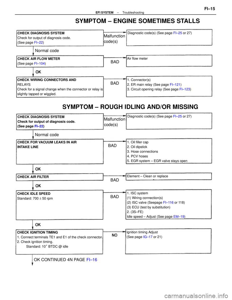
1. ISC system
(1) Wiring connection(s)
(2) ISC valve (Seepage FI±116 or 118)
(3) ECU (test by substitution)
2. (3S±FE)
Idle speed ± Adjust (See page EM±19)
CHECK IGNITION TIMING
1. Connect terminals TE1 and E1 of the check connector.
2. Check ignition timing.
Standard: 10° BTDC @ idle CHECK WIRING CONNECTORS AND
RELAYS
Check for a signal change when the connector or relay is
slightly tapped or wiggled.
1. Oil filler cap
2. Oil dipstick
3. Hose connections
4. PCV hoses
5. EGR system ± EGR valve stays open1. Connector(s)
2. ER main relay (See page FI±121)
3. Circuit opening relay (See page FI±123) CHECK DIAGNOSIS SYSTEM
Check for output of diagnosis code.
(See page FI±22)
CHECK DIAGNOSIS SYSTEM
Check for output of diagnosis code.
(See page FI±22)
SYMPTOM ± ENGINE SOMETIMES STALLS
SYMPTOM ± ROUGH IDLING AND/OR MISSING
CHECK FOR VACUUM LEAKS IN AIR
INTAKE LINE
Ignition timing Adjust
(See page IG±17 or 21) CHECK AIR FLOW METER
(See page FI±104)
CHECK IDLE SPEED
Standard: 700 + 50 rpmDiagnostic code(s) (See page FI±25 or 27)
Diagnostic code(s) (See page FI±25 or 27)
OK CONTINUED 4N PAGE FI±16
Element ± Clean or replace
CHECK AIR FILTER
Malfunction
code(s)
Malfunction
code(s)
Air flow meter
Normal code
Normal code
BAD
BADBAD
BAD BAD
± EFI SYSTEMTroubleshootingFI±15
Page 1030 of 2389
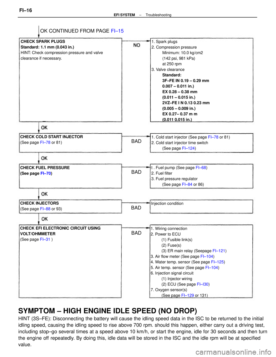
SYMPTOM ± HIGH ENGINE IDLE SPEED (NO DROP)
HINT (3S±FE): Disconnecting the battery will cause the idling speed data in the ISC to be returned to the initial
idling speed, causing the idling speed to rise above 700 rpm. should this happen, either carry out a driving test,
including stop±go several times at a speed above 10 km/h, or start the engine, idle for 30 seconds and then turn
the engine off repeatedly. By doing this, idle data will be stored in the ISC and the idle rpm will be at specified
value.
1. Spark plugs
2. Compression pressure
Minimum: 10.0 kg/cm2
(142 psi, 981 kPa)
at 250 rpm
3. Valve clearance
Standard:
3F±FE IN 0.19 ± 0.29 mm
0.007 ± 0.011 in.)
EX 0.28 ± 0.38 mm
(0.011 ± 0.015 in.)
2VZ±FE I N 0.13 0.23 mm
(0.005 ± 0.009 in.)
EX 0.27± 0.37 m m
(0.011 0.015 in.)
1. Wiring connection
2. Power to ECU
(1) Fusible link(s)
(2) Fuse(s)
(3) ER main relay (Seepage FI±121)
3. Air flow meter (See page FI±104)
4. Water temp. sensor (See page FI±125)
5. Air temp. sensor (See page FI±104)
6. Injection signal circuit
(1) Injector wiring
(2) ECU (See page FI±I30)
7. Oxygen sensor(s)
(See page FI±129 or 131) CHECK SPARK PLUGS
Standard: 1.1 mm (0.043 in.)
HINT: Check compression pressure and valve
clearance if necessary.
CHECK EFI ELECTRONIC CIRCUIT USING
VOLT/OHMMETER
(See page FI±31 )1. Cold start injector (See page FI±78 or 81)
2. Cold start injector time switch
(See page FI±124)
t . Fuel pump (See page FI±68)
2. Fuel filter
3. Fuel pressure regulator
(See page FI±84 or 86) CHECK COLD START INJECTOR
(See page FI±78 or 81)
CHECK FUEL PRESSURE
(See page FI±70)
OK CONTINUED FROM PAGE FI±15
CHECK INJECTORS
(See page FI±88 or 93)Injection condition
BADBAD
BAD
BAD
± EFI SYSTEMTroubleshootingFI±16
Page 1031 of 2389
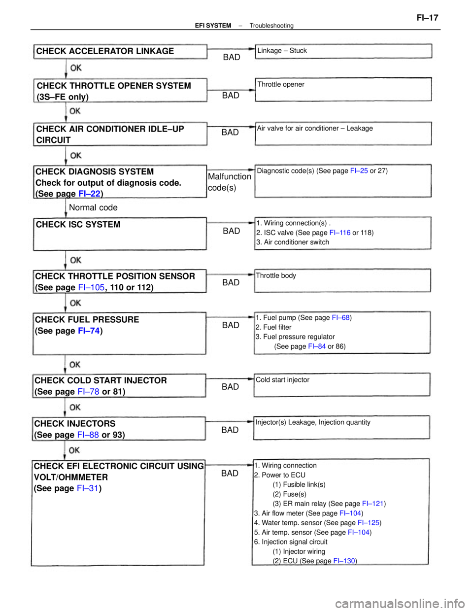
1. Wiring connection
2. Power to ECU
(1) Fusible link(s)
(2) Fuse(s)
(3) ER main relay (See page FI±121)
3. Air flow meter (See page FI±104)
4. Water temp. sensor (See page FI±125)
5. Air temp. sensor (See page FI±104)
6. Injection signal circuit
(1) Injector wiring
(2) ECU (See page FI±130)CHECK EFI ELECTRONIC CIRCUIT USING
VOLT/OHMMETER
(See page FI±31)
1. Fuel pump (See page FI±68)
2. Fuel filter
3. Fuel pressure regulator
(See page FI±84 or 86) 1. Wiring connection(s) .
2. ISC valve (See page FI±116 or 118)
3. Air conditioner switch
CHECK DIAGNOSIS SYSTEM
Check for output of diagnosis code.
(See page FI±22)
CHECK THROTTLE POSITION SENSOR
(See page FI±105, 110 or 112) CHECK THROTTLE OPENER SYSTEM
(3S±FE only)
CHECK AIR CONDITIONER IDLE±UP
CIRCUIT
CHECK COLD START INJECTOR
(See page FI±78 or 81) CHECK FUEL PRESSURE
(See page FI±74)Diagnostic code(s) (See page FI±25 or 27)
Injector(s) Leakage, Injection quantityAir valve for air conditioner ± Leakage
CHECK INJECTORS
(See page FI±88 or 93) CHECK ACCELERATOR LINKAGE
CHECK ISC SYSTEMMalfunction
code(s)
Cold start injectorLinkage ± Stuck
Throttle opener
Throttle body
Normal code
BADBAD
BAD
BADBADBADBAD
BADBAD
± EFI SYSTEMTroubleshootingFI±17
Page 1032 of 2389
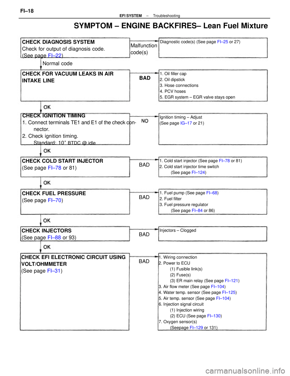
1. Wiring connection
2. Power to ECU
(1) Fusible link(s)
(2) Fuse(s)
(3) ER main relay (See page FI±121)
3. Air flow meter (See page FI±104)
4. Water temp. sensor (See page FI±125)
5. Air temp. sensor (See page FI±104)
6. Injection signal circuit
(1) Injection wiring
(2) ECU (See page FI±130)
7. Oxygen sensor(s)
(Seepage FI±129 or 131)
CHECK IGNITION TIMING
1. Connect terminals TE1 and E1 of the check con-
nector.
2. Check ignition timing.
Standard: 10
° BTDC @ idle
1. Oil filler cap
2. Oil dipstick
3. Hose connections
4. PCV hoses
5. EGR system ± EGR valve stays open
CHECK EFI ELECTRONIC CIRCUIT USING
VOLT/OHMMETER
(See page FI±31)
1. Cold start injector (See page FI±78 or 81)
2. Cold start injector time switch
(See page FI±124)
1. Fuel pump (See page FI±68)
2. Fuel filter
3. Fuel pressure regulator
(See page FI±84 or 86)
CHECK DIAGNOSIS SYSTEM
Check for output of diagnosis code.
(See page FI±22)
SYMPTOM ± ENGINE BACKFIRES± Lean Fuel Mixture
CHECK FOR VACUUM LEAKS IN AIR
INTAKE LINE
CHECK COLD START INJECTOR
(See page FI±78 or 81)
CHECK FUEL PRESSURE
(See page FI±70)
Diagnostic code(s) (See page FI±25 or 27)
Ignition timing ± Adjust
(See page IG±17 or 21)
CHECK INJECTORS
(See page FI±88 or 93)Injectors ± Clogged
Malfunction
code(s)
Normal code
BAD
BAD
BAD BAD
BAD
± EFI SYSTEMTroubleshootingFI±18
Page 1033 of 2389
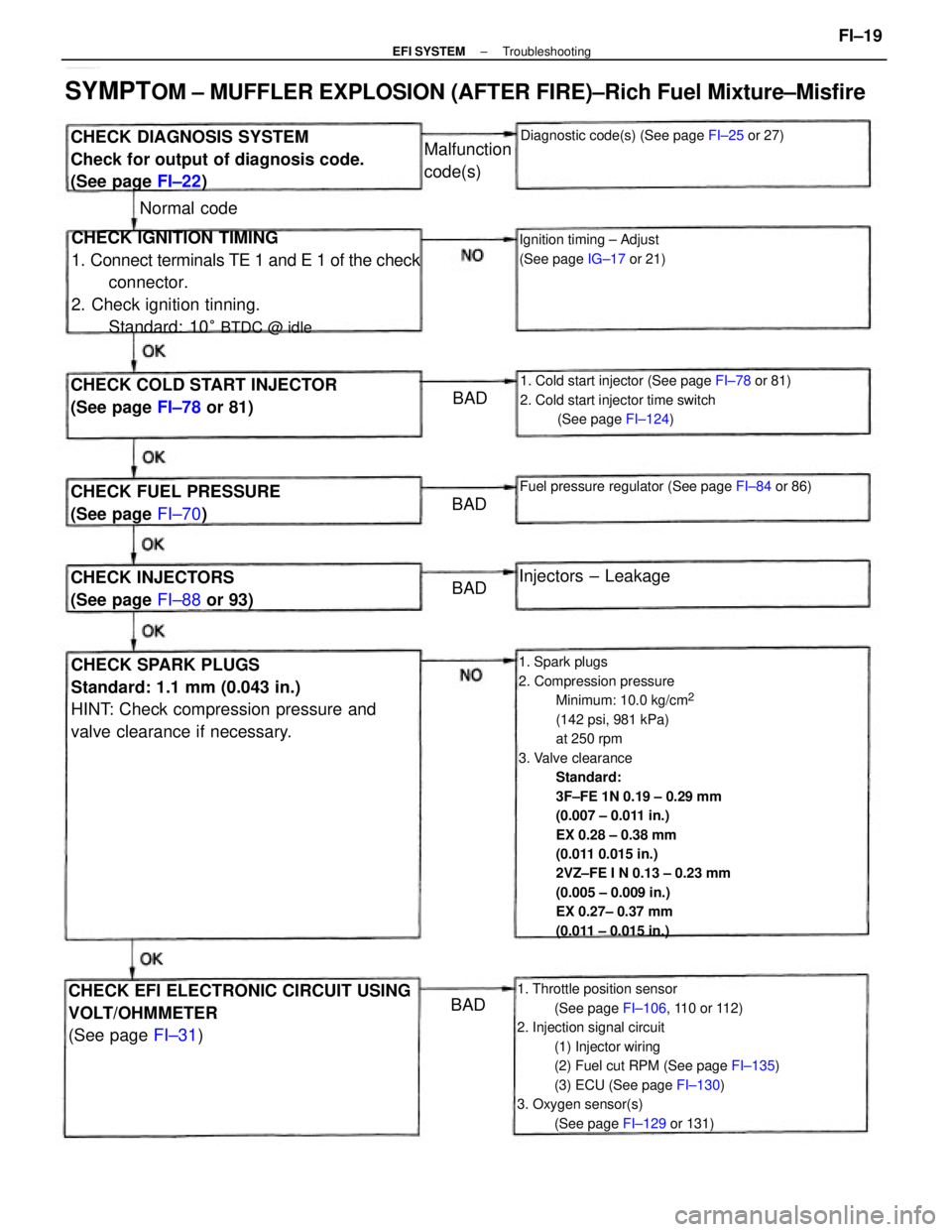
1. Spark plugs
2. Compression pressure
Minimum: 10.0 kg/cm
2
(142 psi, 981 kPa)
at 250 rpm
3. Valve clearance
Standard:
3F±FE 1N 0.19 ± 0.29 mm
(0.007 ± 0.011 in.)
EX 0.28 ± 0.38 mm
(0.011 0.015 in.)
2VZ±FE I N 0.13 ± 0.23 mm
(0.005 ± 0.009 in.)
EX 0.27± 0.37 mm
(0.011 ± 0.015 in.)
1. Throttle position sensor
(See page FI±106, 110 or 112)
2. Injection signal circuit
(1) Injector wiring
(2) Fuel cut RPM (See page FI±135)
(3) ECU (See page FI±130)
3. Oxygen sensor(s)
(See page FI±129 or 131)
CHECK IGNITION TIMING
1. Connect terminals TE 1 and E 1 of the check
connector.
2. Check ignition tinning.
Standard: 10
° BTDC @ idle
CHECK SPARK PLUGS
Standard: 1.1 mm (0.043 in.)
HINT: Check compression pressure and
valve clearance if necessary.
SYMPTOM ± MUFFLER EXPLOSION (AFTER FIRE)±Rich Fuel Mixture±Misfire
CHECK EFI ELECTRONIC CIRCUIT USING
VOLT/OHMMETER
(See page FI±31)
1. Cold start injector (See page FI±78 or 81)
2. Cold start injector time switch
(See page FI±124)
CHECK DIAGNOSIS SYSTEM
Check for output of diagnosis code.
(See page FI±22)
CHECK COLD START INJECTOR
(See page FI±78 or 81)
Fuel pressure regulator (See page FI±84 or 86)CHECK FUEL PRESSURE
(See page FI±70)
Diagnostic code(s) (See page FI±25 or 27)
Ignition timing ± Adjust
(See page IG±17 or 21)
CHECK INJECTORS
(See page FI±88 or 93)Injectors ± Leakage Malfunction
code(s)
Normal code
BAD
BAD
BADBAD
± EFI SYSTEMTroubleshootingFI±19
Page 1035 of 2389
1. Spark plug
2. Compression pressure
Minimum: 10.0 kg/cm
2
(142 psi, 981 kPa)
at 250 rpm
3. Valve clearance
Standard:
3F±FE IN 0.19±0.29 mm
(0.007 ± 0.011 in.)
EX 0.28 ± 0.38 mm
(0.011 ± 0.015 in.)
2VZ±FE IN 0.13±0.23
(0.005 ± 0.009 in.)
EX 0.27± 0.37 mm
(0.011 ± 0.015 in.)
1. Wiring connection
2. Power to ECU
(1) Fusible link(s)
(2) Fuse(s)
(3) ER main relay (See page FI±121)
3. Air flow meter (See page FI±104)
4. Water temp. sensor (See page FI±125)
5. Air temp. sensor (See page FI±104)
6. Throttle position sensor
(See page FI±106, 110 or 112)
7. Injection signal circuit
(1) Injector wiring
(2) ECU (See page FI±130)
CHECK SPARK PLUGS
Standard: 1.1 mm (0±043 in.)
HINT: Check compression pressure and
valve clearance if necessary.
CHECK EFI ELECTRONIC CIRCUIT USING
VOLT/OHMMETER
(See page FI±31) OK CONTINUED FROM PAGE FI±20
BAD
± EFI SYSTEMTroubleshootingFI±21