Page 779 of 2389
Light Control Rheostat
TAIL Fuse
IGN Fuse
Water Temperature Sender Gauge
Ground
Seat Belt Warning Relay
Brake Fluid Level Warning Switch and Parking
Brake Switch
CHARGE Fuse
TCCS ECU ,
A. B. S. ECU
Cruise Control ECU and ECT ECU
Ground
Fuel Sender Gauge Terminal 3
Fuel Sender Gauge Terminal 2
. GAUGE Fuse
DOME Fuse
Door Courtesy Switch
Low Oil Pressure Switch
Light Failure Sensor
Turn Signal Switch Terminal 28
Ground
Turn Signal Switch Terminal 25
Turn Signal Switch Terminal 23 (USA)
HEAD±HI (RH) Fuse (CANADA)
A/T Oil Temperature Switch
Igniter
Combination Meter and Gauges
(w/ Tachometer)
COMBINATION METER CIRCUIT
Wiring Connector Side
No.
± BODY ELECTRICAL SYSTEMCombination MeterBE±33
Page 819 of 2389
HINT: Back±up power refers to the storage voltage for
preset tuning. This is applied even when the ignition
switch is OFF.
Is there back±up power to connectors
behind radio?
Inspect antenna and antenna cable,
and replace as necessary. Check for short circuit in back±up
power source wife harness.Inspect and repair back±up power
wire harness.
Inspect and repair wire harness
for back±up power source.
Temporarily install another
antenna. Okay?Check that antenna plug is
secure in radio.Inspect antenna plug.
Does radio alone work?Reinsert plug. Okay?
Replace tape player.Check DOME fuse.Proceed to Test 3.
Proceed to Test 4. Insert properly.
Replace radio.Replace fuse.
Replace radio. Blows again
TEST 3
TEST 4TEST 2
Blown
Loose Short
Ye sYe s
± BODY ELECTRICAL SYSTEMAudio SystemBE±97
Page 832 of 2389

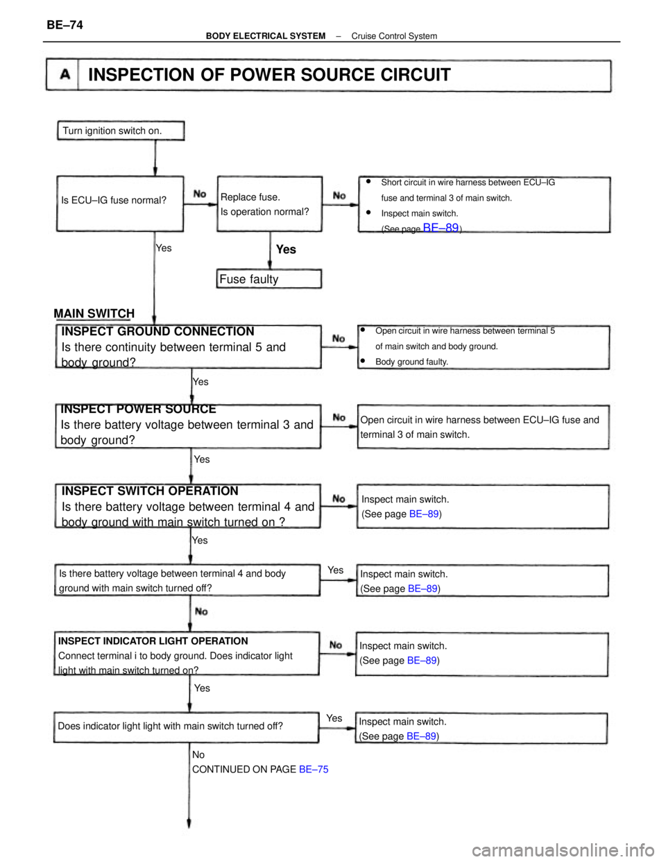
wShort circuit in wire harness between ECU±IG
fuse and terminal 3 of main switch.
wInspect main switch.
(See page
BE±89)
INSPECT SWITCH OPERATION
Is there battery voltage between terminal 4 and
body ground with main switch turned on ? INSPECT POWER SOURCE
Is there battery voltage between terminal 3 and
body ground?
INSPECT INDICATOR LIGHT OPERATION
Connect terminal i to body ground. Does indicator light
light with main switch turned on?
wOpen circuit in wire harness between terminal 5
of main switch and body ground.
wBody ground faulty.
INSPECT GROUND CONNECTION
Is there continuity between terminal 5 and
body ground?
Is there battery voltage between terminal 4 and body
ground with main switch turned off?Open circuit in wire harness between ECU±IG fuse and
terminal 3 of main switch.
INSPECTION OF POWER SOURCE CIRCUIT
No
CONTINUED ON PAGE BE±75 Does indicator light light with main switch turned off?Inspect main switch.
(See page BE±89) Inspect main switch.
(See page BE±89)
Inspect main switch.
(See page BE±89)
Inspect main switch.
(See page BE±89) Replace fuse.
Is operation normal? Turn ignition switch on.
Is ECU±IG fuse normal?
MAIN SWITCHFuse faulty
Ye s Ye s
Ye s Ye s
Ye s
Ye s
Ye s
Ye s
± BODY ELECTRICAL SYSTEMCruise Control SystemBE±74
Page 875 of 2389
ASSEMBLY OF CYLINDER
(See page BR±18)
1. APPLY LITHIUM SOAP BASE GLYCOL GREASE TO
PARTS INDICATED WITH ARROWS
4. INSTALL DUST BOOTS AND SLIDING BUSHING
(a) Install the dust boots into the brake cylinder.
(b) Insure that the boot is secured firmly to the brake cyl-
inder groove.
(c) Install the bushing into the boots.
(d) Insure that the boot is secured firmly to the bushing
groove. 3. INSTALL CYLINDER BOOT AND SET RING IN
CYLINDER 2. INSTALL PISTON SEAL AND PISTON IN CYLINDER
± BRAKE SYSTEMFront BrakeBR±24
Page 891 of 2389
ASSEMBLY OF CYLINDER
(See page BR±34)
1. APPLY LITHIUM SOAP BASE GLYCOL GREASE TO
FOLLOWING PARTS:
(a) Main pin boot
(b) Sliding bushing and dust boots
(e) Piston, piston seal and cylinder boot
5. INSTALL SLIDING BUSHING AND DUST BOOTS
(a) Install the sliding bushing and dust boots into the
brake cylinder.
(b) Insure that the boots are secured firmly to the brake
cylinder groove. 3. INSTALL CYLINDER BOOT AND SET RING IN
CYLINDER
4. INSTALL MAIN PIN BOOT
Install the main pin boot in place. 2. INSTALL PISTON SEAL AND PISTON IN CYLINDER
± BRAKE SYSTEMRear BrakeBR±40
Page 954 of 2389

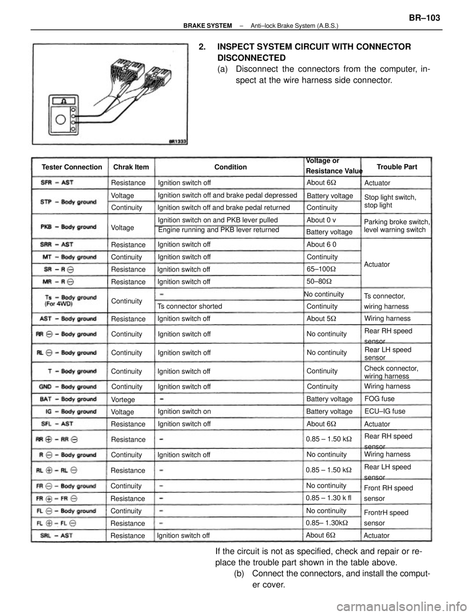
2. INSPECT SYSTEM CIRCUIT WITH CONNECTOR
DISCONNECTED
(a) Disconnect the connectors from the computer, in-
spect at the wire harness side connector.
If the circuit is not as specified, check and repair or re-
place the trouble part shown in the table above.
(b) Connect the connectors, and install the comput-
er cover.
Ignition switch off and brake pedal depressed
Engine running and PKB lever returned Ignition switch off and brake pedal returned
Ignition switch on and PKB lever pulled
Parking broke switch,
level warning switchStop light switch,
stop light Voltage or
Resistance Value
Check connector,
wiring harness
Front RH speed
sensor
FrontrH speed
sensor Ts connector,
wiring harness
Rear RH speed
sensor
Rear RH speed
sensor
Rear LH speed
sensorRear LH speed
sensor Ts connector shorted
Ignition switch offIgnition switch off
Ignition switch off
Ignition switch off Ignition switch off Tester Connection
Ignition switch offIgnition switch off
Ignition switch off
Ignition switch off Ignition switch off Ignition switch off
Ignition switch offIgnition switch off
Ignition switch onBattery voltage
No continuity
Battery voltage
0.85 ± 1.30 k fl
0.85± 1.30k� Battery voltage
Wiring harnessWiring harness
Wiring harness Battery voltage
0.85 ± 1.50 k� 0.85 ± 1.50 k�
No continuityNo continuity
No continuityNo continuityNo continuityTrouble Part
65±100�
ECU±IG fuse Chrak Item
50±80�
About 6� ContinuityResistance
Resistance
About 5� ResistanceAbout 6 0
Resistance
ResistanceAbout 6�
ResistanceContinuity Resistance
Resistance
ResistanceContinuity
ResistanceAbout 6�
ResistanceContinuity
Continuity
Continuity
ContinuityContinuity Continuity
Continuity Continuity
About 0 v
Continuity Continuity
Continuity
Continuity
FOG fuse Condition
ActuatorActuator
Actuator Voltage
VoltageVortege
Actuator Voltage
± BRAKE SYSTEMAnti±lock Brake System (A.B.S.)BR±103
Page 966 of 2389

(c) AS shown in the illustration, mount SST (C) in a vise,
and install the alternator to SST (C).
(d) To loosen the pulley nut turn SST (A) in the direction
shown in the illustration.
NOTICE: To prevent damage to the rotor shaft, do not
loosen the pulley nut more than one±half of a turn.
(e) Remove the alternator from SST (C).
(f) Turn SST (B) and remove SST (A and B).
(g) Remove the pulley nut and pulley.
INSPECTION AND REPAIR OF
ALTERNATOR
Rotor
1. INSPECT ROTOR FOR OPEN CIRCUIT
Using an ohmmeter, check that there is continuity between the slip
rings.
Standard resistance (Cold): 2.8 ± 3.0W
If there is no continuity replace the rotor.4. REMOVE PULLEY
(a) Hold SST(A) with a torque wrench, and tighten SST (B)
clockwise to the specified torque.
SST 09820±63010
Torque: 400 kg±cm (29 ft±Ib, 39 N±m)
(b) Check that SST (A) is secured to the rotor shaft.
(b) Using SST, remove the rectifier end frame.
SST 09286±46011
6. REMOVE ROTOR FROM DRIVE END FRAME5. REMOVE RECTIFIER END FRAME
(a) Remove the four nuts.
± CHARGING SYSTEMAlternatorCH±8
Page 970 of 2389

ASSEMBLY OF ALTERNATOR
(See page CH±6)
1. INSTALL ROTOR TO DRIVE END FRAME
2. ASSEMBLE DRIVE END FRAME AND RECTIFIER END
FRAME
(a) Using a plastic±faced hammer, lightly tap in the end frame.
(b) Install the four nuts.
3. INSTALL PULLEY
(a) Install the pulley to the rotor shaft by tightening the
pulley nut by hand.
(b) Hold SST(A)with a torque wrench, and tighten SST (B) clock-
wise to the specified torque.
SST 09820±63010
Torque: 400 kg±cm (29 ft±Ib, 39 N±m)
(c) Check that SST (A) is secured to the pulley shaft.
(d) As shown in the illustration, mount SST (C) in a vise, and
install the alternator to SST (C).
(e) To torque the pulley nut turn SST (A) in the direction
shown in the illustration.
Torque: 1,125 kg±cm (81 ft±Ib, 110 N±m )
(f) Remove the alternator from SST (C).
(g) Turn SST (6) and remove SST (A and6). 4. IF NECESSARY, REPLACE REAR BEARING
(a) Using SST, remove the bearing cover and bearing.
SST 09820±00021
NOTICE: Be careful not to damage the fan.
(b) Using SST and a press, press in a new bearing and
bearing cover.
SST 09285±76010
± CHARGING SYSTEMAlternatorCH±12