Page 1013 of 2389
B. Inspect relay operation
(a) Apply battery voltage across terminal 2 and 6.
(b) Using an ohmmeter, check that there is no continuity be-
tween terminals 1 and 3.
(c) Check that there is continuity between terminals 1 and 4.
If operation is not as specified, replace the relay.
6. INSPECT No.3 COOLING FAN RELAY
(ºAC FAN NO.3º)
(See procedure EFI Main Relay on page FI±122)
7. INSPECT COOLING FAN MOTORS
(a) Connect battery and ammeter to the fan motor connector.
(b) Check that the fan motor rotates smoothly, and check the
reading on the ammeter.
Standard amperage: No. 1 12.1 ±15.1A
No.2 6.0±7.4A
± COOLING SYSTEMElectric Cooling Fans (2VZ±FE)CO±26
Page 1172 of 2389
INSPECTION OF DASH POT (DP)
SYSTEM
1. WARM UP ENGINE
Allow the engine to normal operating temperature.
2. CHECK IDLE SPEED
Idle speed: 700 rpm
3. REMOVE CAP, FILTER AND SEPARATOR FROM DP
4. CHECK DP SETTING SPEED
(a) Maintain the engine at 2,500 rpm.
(b) Plug the VTV hole, with your finger.
If not as specified, adjust with the DP adjusting screw.
5. REINSTALL DP SEPARATOR, FILTER AND CAP
HINT: Install the filter with the coarser surface facing the at-
mospheric side (outward).
6. CHECK VTV OPERATION
Race the engine at 2,500 rpm for a few seconds, release
the throttle valve and check that the engine returns to idle in
a few seconds.(c) Release the throttle valve.
(d) Check that the DP is set.
DP setting speed: 2,000 rpm
(w/ Cooling fan OFF)
± EMISSION CONTROL SYSTEMS (2VZ±FE)Dash Pot (DP) System (M T only)EC±20
Page 1183 of 2389

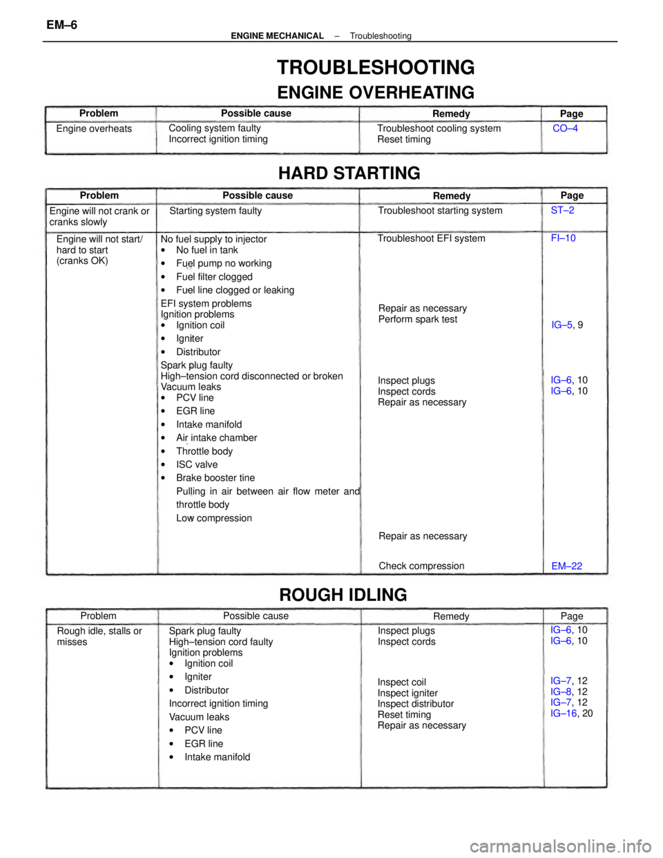
No fuel supply to injector
wNo fuel in tank
wFuel pump no working
wFuel filter clogged
wFuel line clogged or leaking
EFI system problems
Ignition problems
wIgnition coil
wIgniter
wDistributor
Spark plug faulty
High±tension cord disconnected or broken
Vacuum leaks
wPCV line
wEGR line
wIntake manifold
wAir intake chamber
wThrottle body
wISC valve
wBrake booster tine
Pulling in air between air flow meter and
throttle body
Low compression
Spark plug faulty
High±tension cord faulty
Ignition problems
wIgnition coil
wIgniter
wDistributor
Incorrect ignition timing
Vacuum leaks
wPCV line
wEGR line
wIntake manifold
TROUBLESHOOTING
ENGINE OVERHEATING
Inspect coil
Inspect igniter
Inspect distributor
Reset timing
Repair as necessaryInspect plugs
Inspect cords
Repair as necessary Troubleshoot cooling system
Reset timing
Engine will not start/
hard to start
(cranks OK)Cooling system faulty
Incorrect ignition timing
Repair as necessary
Perform spark test Engine will not crank or
cranks slowly
IG±7, 12
IG±8, 12
IG±7, 12
IG±16, 20 Rough idle, stalls or
misses
HARD STARTING
Troubleshoot starting system
Inspect plugs
Inspect cords Troubleshoot EFI system
ROUGH IDLING
Starting system faulty
Check compression Repair as necessary Engine overheats
IG±6, 10
IG±6, 10 IG±6, 10
IG±6, 10 Possible cause
Possible cause Possible cause
Remedy Remedy
Problem
Remedy Problem Problem
IG±5, 9
EM±22Page
Page
Page CO±4
FI±10 ST±2
± ENGINE MECHANICALTroubleshootingEM±6
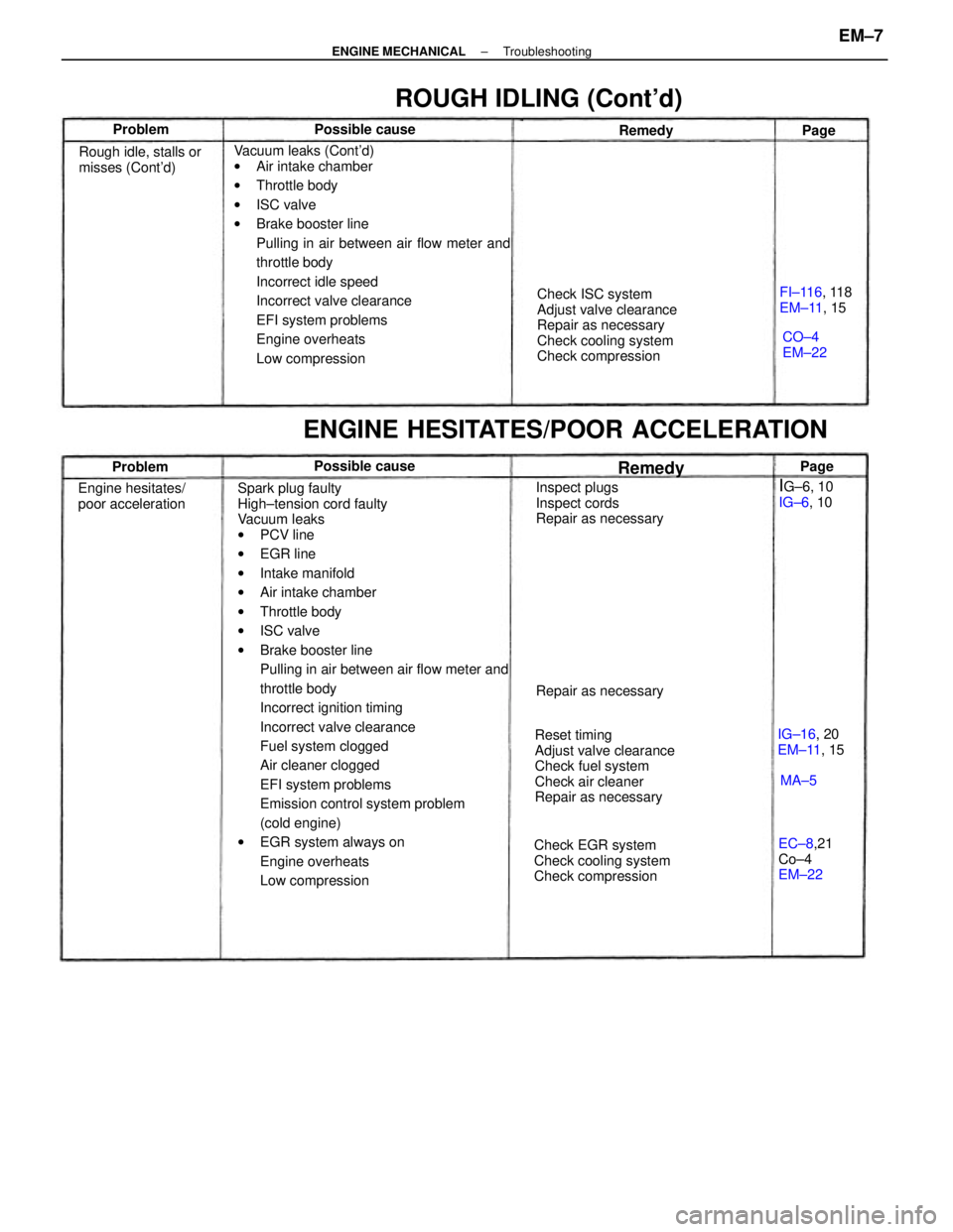
Page 1184 of 2389

Spark plug faulty
High±tension cord faulty
Vacuum leaks
wPCV line
wEGR line
wIntake manifold
wAir intake chamber
wThrottle body
wISC valve
wBrake booster line
Pulling in air between air flow meter and
throttle body
Incorrect ignition timing
Incorrect valve clearance
Fuel system clogged
Air cleaner clogged
EFI system problems
Emission control system problem
(cold engine)
wEGR system always on
Engine overheats
Low compression Vacuum leaks (Cont'd)
wAir intake chamber
wThrottle body
wISC valve
wBrake booster line
Pulling in air between air flow meter and
throttle body
Incorrect idle speed
Incorrect valve clearance
EFI system problems
Engine overheats
Low compressionCheck ISC system
Adjust valve clearance
Repair as necessary
Check cooling system
Check compression
Reset timing
Adjust valve clearance
Check fuel system
Check air cleaner
Repair as necessary
ENGINE HESITATES/POOR ACCELERATION
Check EGR system
Check cooling system
Check compressionInspect plugs
Inspect cords
Repair as necessary
ROUGH IDLING (Cont'd)
Rough idle, stalls or
misses (Cont'd)
Engine hesitates/
poor acceleration
EC±8,21
Co±4
EM±22FI±116, 118
EM±11, 15
IG±16, 20
EM±11, 15 Repair as necessary
IG±6, 10
IG±6, 10 Possible causePossible cause
CO±4
EM±22 Remedy Problem
RemedyProblemPage
MA±5Page
± ENGINE MECHANICALTroubleshootingEM±7
Page 2225 of 2389
Engine coolant x Drain plug
Water pump x Water pump cover
Water pump x Cylinder head
Water by±pass pipe X Water pump
Water inlet housing x Water pump
Oil cooler x Radiator tower tank
Cylinder block x Drain plug
Water pump x Cylinder block
Water inlet x Water pump
Water inlet pipe x Alternator belt adjusting bar
LUBRICATION SYSTEM (3S±FE)
SpecificationsTorque Specifi
cations (3S±FE)
COOLING SYSTEM
Specifications
Torque Specifications (2VZ±FE)
Valve opening temperature
Valve lift at 95°C (203°F) Relief valve opening pressure
Engine coolant capacityEngine coolant capacity
at Idling
at 3,040 rpm
STD
Limit
STD
Limit Body clearance .See page A±20 STD
Limit
Part tightened
Part tightenedSee page A±2
Tip clearance3S±FE
2VZ±FE
Oil pressureThermostat
Oil pumpRadiator
± SERVICE SPECIFICATIONSCooling SystemA±17
Page 2229 of 2389
Engine coolant x Drain plug
Water pump x Water pump cover
Water pump x Cylinder head
Water by±pass pipe X Water pump
Water inlet housing x Water pump
Oil cooler x Radiator tower tank
Cylinder block x Drain plug
Water pump x Cylinder block
Water inlet x Water pump
Water inlet pipe x Alternator belt adjusting bar
LUBRICATION SYSTEM (3S±FE)
SpecificationsTorque Specifi
cations (3S±FE)
COOLING SYSTEM
Specifications
Torque Specifications (2VZ±FE)
Valve opening temperature
Valve lift at 95°C (203°F) Relief valve opening pressure
Engine coolant capacityEngine coolant capacity
at Idling
at 3,040 rpm
STD
Limit
STD
Limit Body clearance .See page A±20 STD
Limit
Part tightened
Part tightenedSee page A±2
Tip clearance3S±FE
2VZ±FE
Oil pressureThermostat
Oil pumpRadiator
± SERVICE SPECIFICATIONSLubrication System (3S±FE)A±17