Page 1005 of 2389
(b) Stake the claws of the tank plates with SST in the nu-
merical order shown in the figure.
SST 09230±00010 4. INSTALL TANK PLATE
Insert new tank plates from both ends in the direction of the
arrows. Firmly set the tank plates in the core plate.3. INSTALL TANK
Install a new O±ring and the tank.
HINT:
wClean the tank and core plate.
5. STAKE CLAWS OF TANK PLATES
(a) Set the punch of SST to ºLOWº.
SST 09230±00010 wTake out any twists.
± COOLING SYSTEMRadiatorCO±18
Page 1006 of 2389
6. CHECK FOR WATER LEAKS
(a) Tighten the drain plug.
(b) Plug the inlet and outlet pipes of the radiator with SST.
SST 09230=00010
(c) Using a radiator cap tester, apply pressure to the radiator.
Test pressure: 1.8 kg/cm
2 (26 psi, 177 kPa) HINT:
wStake with just enough pressure to leave a mark on the
claw. The staked plate height (H) should be as follows:
Plate height (H):
9.0±9.4 mm (0.354±0.370in.)
NOTICE: If the bottom of the core plate is staked with
the SST on the guide block stopper, it may result in
water leakage.
wThe points shown i n the illustration cannot be staked
with the SST. Use pliers and be careful not to damage
the core plates. wDo not stake the areas protruding around the pipes,
brackets or tank ribs.
± COOLING SYSTEMRadiatorCO±19
Page 1007 of 2389

INSTALLATION OF RADIATOR
1. INSTALL ELECTRIC COOLING FANS TO RADIATOR
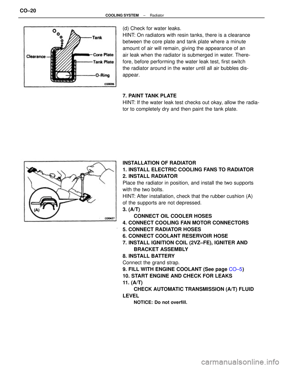
2. INSTALL RADIATOR
Place the radiator in position, and install the two supports
with the two bolts.
HINT: After installation, check that the rubber cushion (A)
of the supports are not depressed.
3. (A/T)
CONNECT OIL COOLER HOSES
4. CONNECT COOLING FAN MOTOR CONNECTORS
5. CONNECT RADIATOR HOSES
6. CONNECT COOLANT RESERVOIR HOSE
7. INSTALL IGNITION COIL (2VZ±FE), IGNITER AND
BRACKET ASSEMBLY
8. INSTALL BATTERY
Connect the grand strap.
9. FILL WITH ENGINE COOLANT (See page CO±5)
10. START ENGINE AND CHECK FOR LEAKS
11. (A/T)
CHECK AUTOMATIC TRANSMISSION (A/T) FLUID
LEVEL
NOTICE: Do not overfill.
(d) Check for water leaks.
HINT: On radiators with resin tanks, there is a clearance
between the core plate and tank plate where a minute
amount of air will remain, giving the appearance of an
air leak when the radiator is submerged in water. There-
fore, before performing the water leak test, first switch
the radiator around in the water until all air bubbles dis-
appear.
7. PAINT TANK PLATE
HINT: If the water leak test checks out okay, allow the radia-
tor to completely dry and then paint the tank plate.
± COOLING SYSTEMRadiatorCO±20
Page 1008 of 2389
ON±VEHICLE INSPECTION
Low Temperature (Below 835C (1815F))
1. TURN IGNITION SWITCH ºONº
Check that the fan stops.
If not, check the cooling fan relay and water temperature
switch, and check for a separated connector or severed
wire between the cooling fan relay and water temperature
switch.
2. DISCONNECT WATER TEMPERATURE SWITCH
CONNECTOR
Check that fan rotates.
If not, check the cooling fan relay, fan motor, engine main
relay and fuse, and check for a short circuit between the
cooling fan relay and water temperature switch.
3: CONNECT WATER TEMPERATURE SWITCH
CONNECTOR
ELECTRIC COOLING FAN (3S±FE)
LOCATION OF ELECTRIC COOLING
FAN COMPONENTS
± COOLING SYSTEMElectric Cooling Fan (3S±FE)CO±21
Page 1009 of 2389

INSPECTION OF ELECTRIC COOLING
FAN COMPONENTS
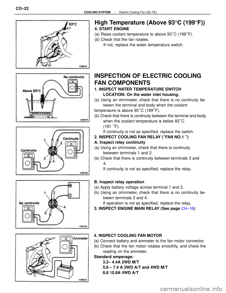
1. INSPECT WATER TEMPERATURE SWITCH
LOCATION: On the water inlet housing.
(a) Using an ohmmeter, check that there is no continuity be-
tween the terminal and body when the coolant
temperature is above 93°C (199°F).
(b) Check that there is continuity between the terminal and body
when the coolant temperature is below 83°C
(181 °F).
If continuity is not as specified, replace the switch.
2. INSPECT COOLING FAN RELAY (ºFAN NO.1 º)
A. Inspect relay continuity
(a) Using an ohmmeter, check that there is continuity
between terminals 1 and 2.
(b) Check that there is continuity between terminals 3 and
4.
If continuity is not as specified, replace the relay.
4. INSPECT COOLING FAN MOTOR
(a) Connect battery and ammeter to the fan motor connector.
(b) Check that the fan motor rotates smoothly, and check the
reading on the ammeter.
Standard amperage:
3.2± 4.4A 2WD M/T
5.8 ± 7.4 A 2WD A/T and 4WD M/T
8.8 10.8A 4WD A/T B. Inspect relay operation
(a) Apply battery voltage across terminal 1 and 2.
(b) Using an ohmmeter, check that there is no continuity be-
tween terminals 3 and 4.
If operation is not as specified, replace the relay.
3. INSPECT ENGINE MAIN RELAY (See page CH±16)
High Temperature (Above 935C (1995F))
4. START ENGINE
(a) Raise coolant temperature to above 93°C (199°F).
(b) Check that the fan rotates.
If not, replace the water temperature switch.
± COOLING SYSTEMElectric Cooling Fan (3S±FE)CO±22
Page 1010 of 2389
ELECTRIC COOLING FANS (2VZ±FE)
SYSTEM CIRCUIT
LOCATION OF ELECTRIC COOLING FAN
COMPONENTS
± COOLING SYSTEMElectric Cooling Fans (2VZ±FE)CO±23
Page 1011 of 2389

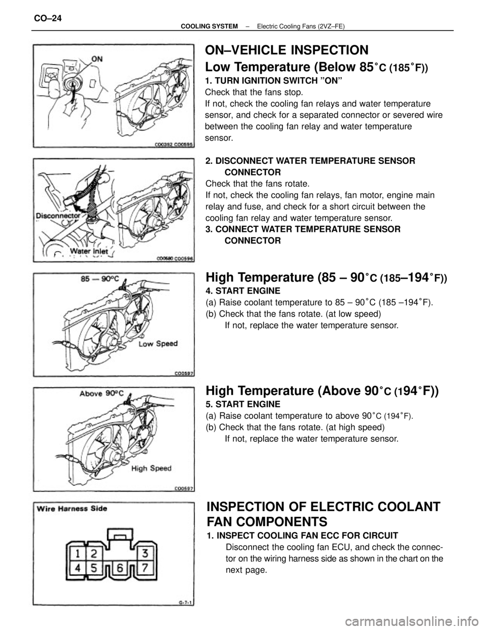
ON±VEHICLE INSPECTION
Low Temperature (Below 85
°C (185°F))
1. TURN IGNITION SWITCH ºONº
Check that the fans stop.
If not, check the cooling fan relays and water temperature
sensor, and check for a separated connector or severed wire
between the cooling fan relay and water temperature
sensor.
2. DISCONNECT WATER TEMPERATURE SENSOR
CONNECTOR
Check that the fans rotate.
If not, check the cooling fan relays, fan motor, engine main
relay and fuse, and check for a short circuit between the
cooling fan relay and water temperature sensor.
3. CONNECT WATER TEMPERATURE SENSOR
CONNECTOR
INSPECTION OF ELECTRIC COOLANT
FAN COMPONENTS
1. INSPECT COOLING FAN ECC FOR CIRCUIT
Disconnect the cooling fan ECU, and check the connec-
tor on the wiring harness side as shown in the chart on the
next page.
High Temperature (85 ± 90°C (185±194°F))
4. START ENGINE
(a) Raise coolant temperature to 85 ± 90°C (185 ±194°F).
(b) Check that the fans rotate. (at low speed)
If not, replace the water temperature sensor.
High Temperature (Above 90°C (194°F))
5. START ENGINE
(a) Raise coolant temperature to above 90
°C (194°F).
(b) Check that the fans rotate. (at high speed)
If not, replace the water temperature sensor.
± COOLING SYSTEMElectric Cooling Fans (2VZ±FE)CO±24
Page 1012 of 2389
5. INSPECT NO±2 COOLING FAN RELAY
(ºAC FAN NO.2º)
A. Inspect relay continuity
(a) Using an ohmmeter, check that there is continuity between
terminals 2 and 6.
(b) Check that there is continuity between terminals 1 and 3.
(c) Check that there is no continuity between terminals 1
and 4.
If continuity is not as specified, replace the relay. 2. INSPECT WATER TEMPERATURE SENSOR
Using an ohmmeter, measure the resistance between the
terminals.
Resistance:
Approx. 1.53 k� at 80°C (176° F)
Approx. 1.18 k� at 90°C (194° F)
Approx. 1.03 k� at 95°C (203°F)
If resistance is not as specified, replace the sensor.
3. INSPECT ENGINE MAIN RELAY (See page CH±16)
4. INSPECT NO.1 COOLING FAN RELAY (ºFAN NO.1 º)
(See page CO±22)
Ignition switch ON Ignition switch ON Tester connectionSpecified valve Condition
Battery voltageBattery voltage
Coolant temp.
Continuity
ContinuityContinuity ResistanceContinuity Check for
Voltage
Voltage
± COOLING SYSTEMElectric Cooling Fans (2VZ±FE)CO±25