Page 1416 of 2389
4. INSTALL SUSPENSION LOWER CROSSMEMBER
Temporarily install the two bolts and two nuts by hand,
and then torque the bolts and nuts.
Torque: 2,110 kg±cm (153 ft±Ib, 207 N±m)
HINT: Temporarily first install the lower arm shaft to the
body with lower arm shaft installation bolt and nut and
then temporarily install the suspension lower cross-
member. 3. CONNECT LOWER BALL JOINT TO STEERING
KNUCKLE
Connect the steering knuckle to the lower ball joint and
torque the two bolts.
Torque: 1,150 kg±cm (83 ft±Ib, 113 N ± m )
5. INSTALL WHEELS AND LOWER VEHICLE
(a) Install the wheels.
(b) Remove the stands and bounce the vehicle up and
down to stabilize the suspension.
6. TORQUE LOWER SUSPENSION ARM INSTALLATION
NUT
Torque: Stabilizer bar X Lower suspension arm
2,160 kg±cm (156 ft±Ib, 212 N±m)
Torque: Lower arm shaft x Lower suspension arm
2,160 kg±cm (156 ft±lb , 212 N±m)
7. CHECK FRONT WHEEL ALIGNMENT
± FRONT AXLE AND SUSPENSIONFront SuspensionFA±59
Page 1419 of 2389
8. TORQUE STABILIZER NUTS
Torque the stabilizer nuts holding the stabilizer bar to
the lower arm.
Torque: 2,160 kg±mm (156 ft±Ib, 212 N±m)
7. INSTALL WHEELS AND LOWER VEHICLE
(a) Install the wheels.
(b) Remove the stands and bounce the vehicle up and
down to stabilize the suspension.
9. CHECK FRONT WHEEL ALIGNMENT
(See page FA ± 3)
± FRONT AXLE AND SUSPENSIONFront SuspensionFA±62
Page 1860 of 2389

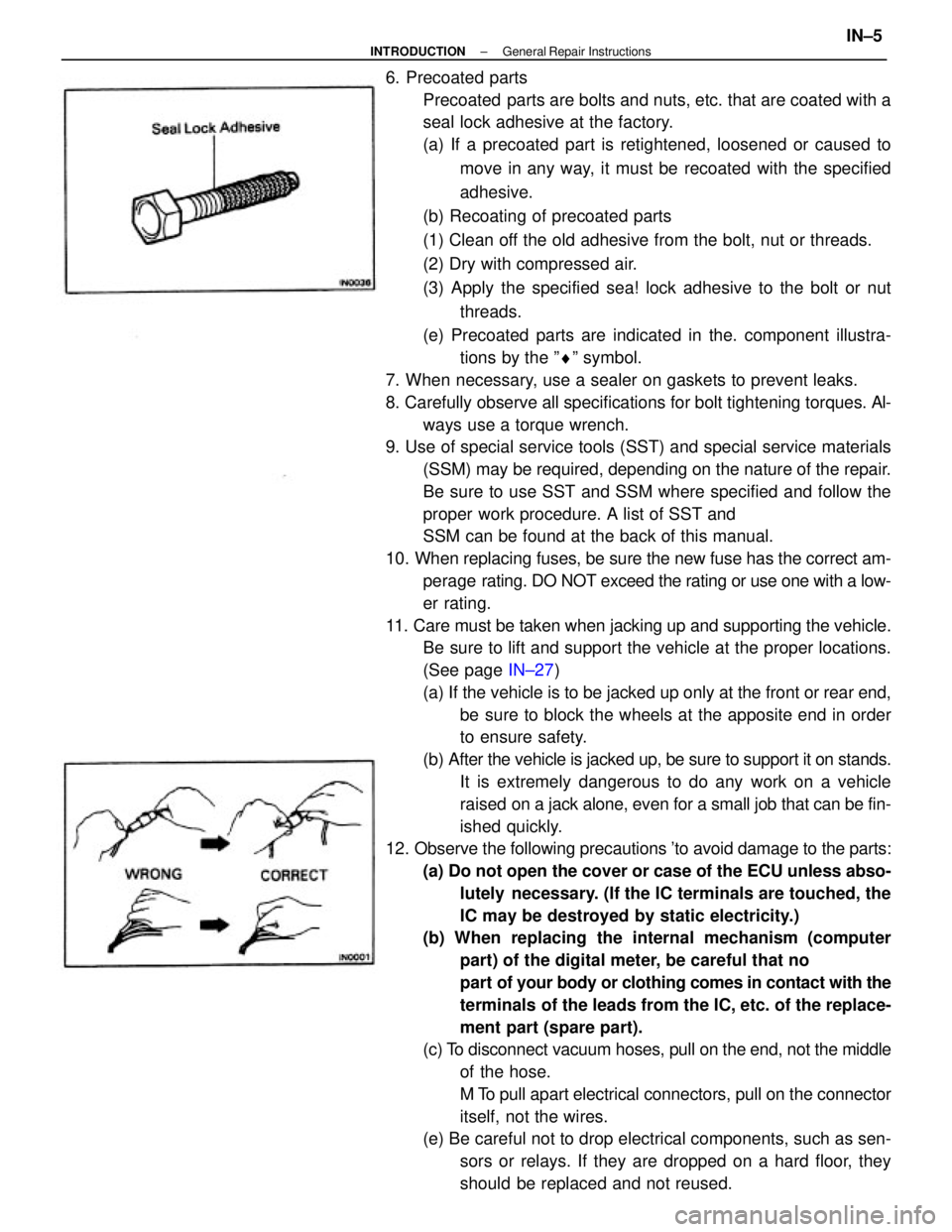
6. Precoated parts
Precoated parts are bolts and nuts, etc. that are coated with a
seal lock adhesive at the factory.
(a) If a precoated part is retightened, loosened or caused to
move in any way, it must be recoated with the specified
adhesive.
(b) Recoating of precoated parts
(1) Clean off the old adhesive from the bolt, nut or threads.
(2) Dry with compressed air.
(3) Apply the specified sea! lock adhesive to the bolt or nut
threads.
(e) Precoated parts are indicated in the. component illustra-
tions by the ºrº symbol.
7. When necessary, use a sealer on gaskets to prevent leaks.
8. Carefully observe all specifications for bolt tightening torques. Al-
ways use a torque wrench.
9. Use of special service tools (SST) and special service materials
(SSM) may be required, depending on the nature of the repair.
Be sure to use SST and SSM where specified and follow the
proper work procedure. A list of SST and
SSM can be found at the back of this manual.
10. When replacing fuses, be sure the new fuse has the correct am-
perage rating. DO NOT exceed the rating or use one with a low-
er rating.
11. Care must be taken when jacking up and supporting the vehicle.
Be sure to lift and support the vehicle at the proper locations.
(See page IN±27)
(a) If the vehicle is to be jacked up only at the front or rear end,
be sure to block the wheels at the apposite end in order
to ensure safety.
(b) After the vehicle is jacked up, be sure to support it on stands.
It is extremely dangerous to do any work on a vehicle
raised on a jack alone, even for a small job that can be fin-
ished quickly.
12. Observe the following precautions 'to avoid damage to the parts:
(a) Do not open the cover or case of the ECU unless abso-
lutely necessary. (If the IC terminals are touched, the
IC may be destroyed by static electricity.)
(b) When replacing the internal mechanism (computer
part) of the digital meter, be careful that no
part of your body or clothing comes in contact with the
terminals of the leads from the IC, etc. of the replace-
ment part (spare part).
(c) To disconnect vacuum hoses, pull on the end, not the middle
of the hose.
M To pull apart electrical connectors, pull on the connector
itself, not the wires.
(e) Be careful not to drop electrical components, such as sen-
sors or relays. If they are dropped on a hard floor, they
should be replaced and not reused.
± INTRODUCTIONGeneral Repair InstructionsIN±5
Page 1927 of 2389

23. FINAL INSPECTION
(a) Check the operation of the body parts:
wHood
Auxiliary catch operation properly
Hood locks securely when closed
wFront and rear doors
Door locks operate properly
Doors close properly
wLuggage compartment door and back door
Door sock operates properly
wSeats
Seat adjusts easily and locks securely in any position
Front seat back locks securely in any position
Folding±down rear seat backs lock securely
(b) Road test
wCheck the engine and chassis for abnormal noises.
wCheck that the vehicle does not wander or pull to one side.
wCheck that the brakes work properly and do not drag.
wPerform bedding down of the parking brake shoes and drum.
(See page MA±8)
(c) Be sure to deliver a clean car especially check:
wSteering wheel
wShift lever knob
wAll switch knobs
wDoor handles
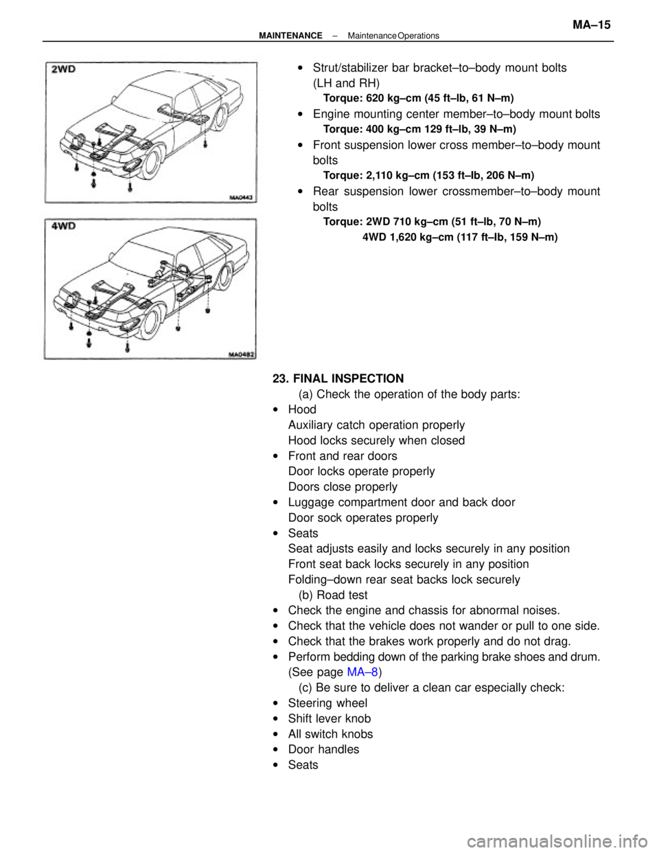
wSeatswStrut/stabilizer bar bracket±to±body mount bolts
(LH and RH)
Torque: 620 kg±cm (45 ft±lb, 61 N±m)
wEngine mounting center member±to±body mount bolts
Torque: 400 kg±cm 129 ft±lb, 39 N±m)
wFront suspension lower cross member±to±body mount
bolts
Torque: 2,110 kg±cm (153 ft±Ib, 206 N±m)
wRear suspension lower crossmember±to±body mount
bolts
Torque: 2WD 710 kg±cm (51 ft±lb, 70 N±m)
4WD 1,620 kg±cm (117 ft±Ib, 159 N±m)
± MAINTENANCEMaintenance OperationsMA±15
Page 2156 of 2389
5. INSTALL WHEELS AND LOWER VEHICLE
(a) Install the wheels.
(b) Remove the stands and bounce the vehicle up and
down to stabilize the suspension.
6. TORQUE AXLE CARRIER MOUNTING BOLTS
Torque the axle carrier mounting blots with the vehicle
weight on the suspension.
Torque:
Strut rod x Axle carrier
1,150 kg±cm (83 ft±Ib, 113 N±m)
No. 1 and No. 2 suspension arm x Axle carrier
1,850 kg±cm (134 ft±Ib, 181 N±m)
7. BLEED BRAKE SYSTEM
(See page BR±7)
8. CHECK REAR WHEEL ALIGNMENT
(See page RA±3) 3. TORQUE BRAKE TUBE
Using SST, torque the brake tube union.
SST 09751±36011
4. INSTALL BRAKE DRUM(b) Temporarily connect the brake tube to the backing
plate.
(c) Install the axle hub and torque the four
bolts.
Torque: 820 kg±cm (59 ft±Ib, 80 N ± m )
± REAR AXLE AND SUSPENSIONRear Axle Hub and Carrier (FWD)RA±10
Page 2165 of 2389
20. TORQUE AXLE CARRIER MOUNTING BOLTS
Torque the axle carrier mounting bolts with the vehicle
weight on the suspension.
Torque: Strut rod x Axle carrier
1,150 kg±cm (83 ft±Ib, 113 N±m)
No. 1 and No. 2 suspension arm x Axle carrier
1,250 kg±cm (90 ft±Ib, 123 N±m)
21. CHECK REAR WHEEL ALIGNMENT
(See page RA±31) 18. INSTALL PLATE WASHER, BEARING LOCK NUT,
BEARING LOCK NUT CAP AND NEW COTTER PIN
(a) Install the plate washer and lock nut.
(b) With the parking brake engaged, and tighten the nut.
Torque: 1,900 kg±cm (137 ft±Ib, 186 N±m)
(c) Install the lock nut cap and a new cotter pin.
19. INSTALL WHEELS AND LOWER VEHICLE
(a) Install the wheel.
(b) Remove the stands and bounce the vehicle up and
down to stabilize the suspension.
± REAR AXLE AND SUSPENSIONRear Axle Hub and Carrier (4WD)RA±19
Page 2200 of 2389
4. INSTALL BRAKE HOSE AND TUBE
(a) Temporarily connect the brake tube to the backing
plate.
(b) Temporarily connect the brake tube to the brake hose.
(c) Install the clip.
(d) Using SST, torque the two brake tube union nuts.
SST 09751±36011
Torque: 155 kg±cm (11 ft±Ib, 15 N±m )
5. INSTALL TONNEAU COVER HOLDER (Wagon)
6. BLEED BRAKE LINE
(See page BR±7)
7. CHECK WHEEL ALIGNMENT
(See page RA±3)
± REAR AXLE AND SUSPENSIONRear Suspension (FWD)RA±54
Page 2203 of 2389
6. TORQUE NO.1 AND NO.2 SUSPENSION ARM
INSTALLATION BOLTS
(a) Align the matchmarks on the cam and the body torque
the installation bolt with the vehicle weight on the
suspension.
Torque: 1,150 kg±cm (83 ft±Ib, 113 N±m)
3. CONNECT NO.1 AND NO.2 SUSPENSION ARM TO
AXLE CARRIER
Connect the No. 1 and No.2 suspension arms with the
bolt and the two retainers to the axle carrier and tempo-
rarily install the nut.
5. INSTALL WHEELS AND LOWER VEHICLE
(a) Install the wheels.
(b) Remove the stands and bounce the vehicle up and
down to stabilize the suspension. 4. CONNECT STRUT BAR TO AXLE CARRIER
Connect the strut rod to the axle carrier and temporarily
install the bolt and nut.(a) Place the No.2 suspension arm in position.
(b) Temporarily install the cam bolt and cam to the
body.
± REAR AXLE AND SUSPENSIONRear Suspension (FIND)RA±57