Page 859 of 2389

CHECK AND ADJUSTMENT OF PARKING
BRAKE
1. CHECK THAT PARKING BRAKE LEVER TRAVEL IS
CORRECT
Pull the parking brake lever all the way up, and count the num-
ber of clicks.
Parking brake levertravel at 20 kg (44.1 Ib, 196 N):
5 ± 8 clicks
If incorrect, adjust the parking brake.
2. IF NECESSARY, ADJUST PARKING BRAKE LEVER
TRAVEL
HINT: Before adjusting the parking brake, make sure that the
rear brake shoe clearance has been adjusted.
For shoe clearance adjustment, see steps 8 and 9 on page
BR±32 or step 8 on page 48.
(a) Remove the console box.
(b) Loosen the lock nut and turn the adjusting nut until the
lever travel is correct.
(e) Tighten the lock nut.
Torque: 55 kg±cm (48 in.±Ib, 5.4 N±m)
(d) Install the console box. 3. BEGIN BLEEDING AIR FROM BRAKE OR WHEEL
CYLINDER WITH LONGEST HYDRAULIC LINE
(a) Connect the vinyl tube to the brake or wheel cylinder
bleeder plug, and insert the other end of tube in a
halffull container of brake fluid.
(b) Slowly pump the brake pedal several times.
(c) While having an assistant press on the pedal, loosen
the bleeder plug until fluid starts to runout. Then close
the bleeder plug.
(d) Repeat (b) and (c) until there are no more air bubbles
in the fluid.
(e) Tighten the bleeder plug.
Bleeder plug tightening torque:
85 kg±cm (74 in.±!b, 8.3 N±m)
4. REPEAT PROCEDURE FOR EACH WHEEL(c) Block off the outer holes with your fingers, and re-
lease the brake pedal.
(d) Repeat (b) and (c) three or four times.
± BRAKE SYSTEMChecks and AdjustmentsBR±8
Page 870 of 2389
2. INSPECT PAD LINING THICKNESS
Check the pad thickness through the cylinder inspection
hole and replace pads if not within specification.
Minimum thickness: 1.0 mm (0.039 in.)
4. REMOVE FOLLOWING PARTS:
(a) Two anti±squeal springs.
(b) Two brake pads
(c) Two or four anti±squeal shims
(d) Two pad wear indicator plates
(e) Four pad support plates 1. REMOVE FRONT WHEEL
Remove the wheel and temporarily fasten the rotor disc
with the hub nuts.
(b) Remove the brake cylinder and suspend it so the hose
is not stretched.
HINT: Do not disconnect the brake hose. 3. REMOVE CYLINDER FROM TORQUE PLATE
(a) Remove two installation bolts from the torque plate.
± BRAKE SYSTEMFront BrakeBR±19
Page 872 of 2389
REMOVAL OF CYLINDER
(See page BR±18)
1. DISCONNECT BRAKE LINE
Remove the union bolt and disconnect the brake line. Use
a container to catch the brake fluid.(d) Install and torque two installation bolts.
Torque: 400 kg±cm (29 ft±Ib, 39 N¿m)
10. INSTALL FRONT WHEEL
11. CHECK THAT FLUID LEVEL IS MAX LINE
2. REMOVE CYLINDER FROM TORQUE PLATE
Remove the two installation bolts and cylinder.
3. REMOVE PADS
(See step 4 on page BR±19)
± BRAKE SYSTEMFront BrakeBR±21
Page 881 of 2389
1. ASSEMBLE WHEEL CYLINDER
(a) Apply lithium soap base glycol grease to the cups
and pistons as shown.
(b) Assemble the wheel cylinder.
HINT: Install in proper direction only.
wSpring
wTwo cups
wTwo pistons
wTwo boots .
2. INSTALL WHEEL CYLINDER
Install the wheel cylinder on the backing plate with two
bolts.
Torque: 100 kg±cm (7 ft±Ib, 10 N±m)
INSTALLATION OF REAR BRAKE
(See page BR±26)
HINT: Assemble the parts in the correct direction as
shown.
3. CONNECT BRAKE TUBE TO WHEEL CYLINDER
Using SST, connect the brake tube.
SST 09751±36011
Torque: 155 kg±crn (11 ft±Ib, 15 N±m)
± BRAKE SYSTEMRear BrakeBR±30
Page 887 of 2389
9. INSTALL CYLINDER
(a) Draw out a small amount of brake fluid from the res-
ervoir.
(b) Press in piston with a hammer handle or an equiva-
lent.
HINT: Always change the pad on one wheel at a time as
there is a possibility of the opposite piston flying out.
(c) Insert the brake cylinder carefully so the boot is not
wedged. 8. INSTALL NEW PADS
(a) Install the two anti±squeal shims to the each pad.
HINT: Apply disc brake grease to the both side of the inner
anti±squeal shim.
(b) Install the two pads so the wear indicator plate is at
the bottom side.
NOTICE: Do not allow oil or grease to get on the rub±
bing face.
(d) Install and. torque the installation
bolt.
Torque: 200 kg±cm (14 ft±Ib, 20 N±m)
10. INSTALL REAR WHEEL
11. FILL BRAKE FLUID
± BRAKE SYSTEMRear BrakeBR±36
Page 985 of 2389

INSTALLATION OF CLUTCH UNIT
(See page CL±8)
1. INSTALL CLUTCH DISC AND COVER ON FLYWHEEL
(a) Insert SST in the clutch disc, and then set them and the cover
in position.
SST S51 Transaxle
09301±32010
E52, E56F5 Transaxle
09301±17010
(b) Align the matchmarks on the clutch cover and flywheel.
(e) Torque the bolts on the clutch cover in the order shown.
Torque: 195 kg±cm (14 ft±Ib, 19 N±m)
HINT: Temporarily tighten the No.1 and No.2 bolts. 5. INSPECT RELEASE BEARING
Turn the bearing by hand while applying force in the axial
direction.
HINT: The bearing is permanently lubricated and requires
no cleaning or lubrication.
If a problem is found, replace the bearing together with the
hub.
2. CHECK DIAPHRAGM SPRING TIP ALIGNMENT
Using a dial indicator with roller instrument, check the
diaphragm spring tip alignment.
Maximum non±alignment: 0.5 mm (0.020 in.)
If alignment is not as specified, using SST, adjust the
diaphragm spring tip alignment.
SST 09333±00013
3. APPLY MOLYBDENUM DISULPHIDE LITHIUM BASE
GREASE(NLGI N0.2) TO FOLLOWING PARTS:
(a) Release fork and hub contact points.
(b) Release fork and push rod contact point.
(e) Release fork pivot point.
± CLUTCHClutch UnitCL±11
Page 1210 of 2389

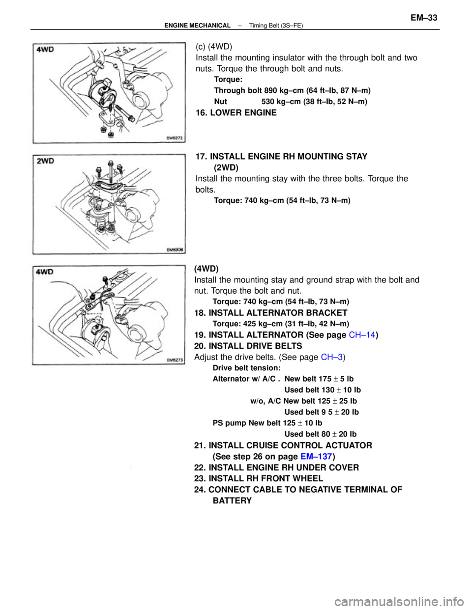
(4WD)
Install the mounting stay and ground strap with the bolt and
nut. Torque the bolt and nut.
Torque: 740 kg±cm (54 ft±Ib, 73 N±m)
18. INSTALL ALTERNATOR BRACKET
Torque: 425 kg±cm (31 ft±Ib, 42 N±m)
19. INSTALL ALTERNATOR (See page CH±14)
20. INSTALL DRIVE BELTS
Adjust the drive belts. (See page CH±3)
Drive belt tension:
Alternator w/ A/C . New belt 175 + 5 lb
Used belt 130 + 10 Ib
w/o, A/C New belt 125 + 25 Ib
Used belt 9 5 + 20 Ib
PS pump New belt 125 + 10 lb
Used belt 80 + 20 Ib
21. INSTALL CRUISE CONTROL ACTUATOR
(See step 26 on page EM±137)
22. INSTALL ENGINE RH UNDER COVER
23. INSTALL RH FRONT WHEEL
24. CONNECT CABLE TO NEGATIVE TERMINAL OF
BATTERY (c) (4WD)
Install the mounting insulator with the through bolt and two
nuts. Torque the through bolt and nuts.
Torque:
Through bolt 890 kg±cm (64 ft±Ib, 87 N±m)
Nut 530 kg±cm (38 ft±Ib, 52 N±m)
16. LOWER ENGINE
17. INSTALL ENGINE RH MOUNTING STAY
(2WD)
Install the mounting stay with the three bolts. Torque the
bolts.
Torque: 740 kg±cm (54 ft±lb, 73 N±m)
± ENGINE MECHANICALTiming Belt (3S±FE)EM±33
Page 1224 of 2389

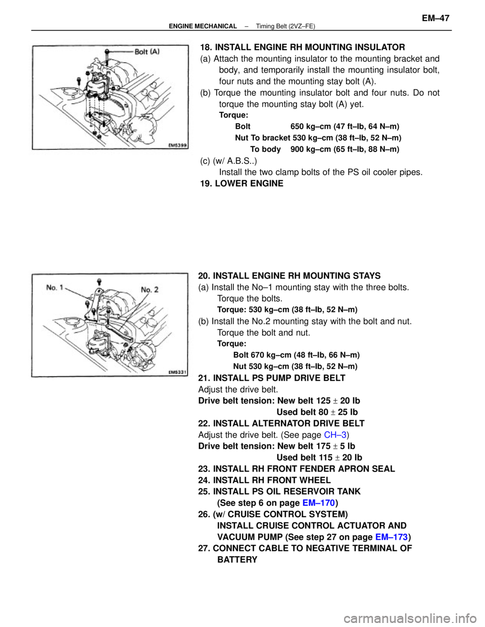
20. INSTALL ENGINE RH MOUNTING STAYS
(a) Install the No±1 mounting stay with the three bolts.
Torque the bolts.
Torque: 530 kg±cm (38 ft±Ib, 52 N±m)
(b) Install the No.2 mounting stay with the bolt and nut.
Torque the bolt and nut.
Torque:
Bolt 670 kg±cm (48 ft±Ib, 66 N±m)
Nut 530 kg±cm (38 ft±Ib, 52 N±m)
21. INSTALL PS PUMP DRIVE BELT
Adjust the drive belt.
Drive belt tension: New belt 125
+ 20 Ib
Used belt 80
+ 25 Ib
22. INSTALL ALTERNATOR DRIVE BELT
Adjust the drive belt. (See page CH±3)
Drive belt tension: New belt 175
+ 5 Ib
Used belt 115
+ 20 Ib
23. INSTALL RH FRONT FENDER APRON SEAL
24. INSTALL RH FRONT WHEEL
25. INSTALL PS OIL RESERVOIR TANK
(See step 6 on page EM±170)
26. (w/ CRUISE CONTROL SYSTEM)
INSTALL CRUISE CONTROL ACTUATOR AND
VACUUM PUMP (See step 27 on page EM±173)
27. CONNECT CABLE TO NEGATIVE TERMINAL OF
BATTERY 18. INSTALL ENGINE RH MOUNTING INSULATOR
(a) Attach the mounting insulator to the mounting bracket and
body, and temporarily install the mounting insulator bolt,
four nuts and the mounting stay bolt (A).
(b) Torque the mounting insulator bolt and four nuts. Do not
torque the mounting stay bolt (A) yet.
Torque:
Bolt 650 kg±cm (47 ft±Ib, 64 N±m)
Nut To bracket 530 kg±cm (38 ft±lb, 52 N±m)
To body 900 kg±cm (65 ft±lb, 88 N±m)
(c) (w/ A.B.S..)
Install the two clamp bolts of the PS oil cooler pipes.
19. LOWER ENGINE
± ENGINE MECHANICALTiming Belt (2VZ±FE)EM±47