Page 1838 of 2389

SPARK TEST
CHECK THAT SPARK OCCURS
(a) Disconnect the high±tension cords from the spark plugs.
(b) Remove the spark plugs.
(c) Install the spark plugs to each high±te")
ON±VEHICLE INSPECTION (3S±FE)
SPARK TEST
CHECK THAT SPARK OCCURS
(a) Disconnect the high±tension cords from the spark plugs.
(b) Remove the spark plugs.
(c) Install the spark plugs to each high±tension cord.
(d) Ground the spark plug.
(e) Check if spark occurs while engine is being cranked.
HINT: To prevent gasoline from being injected from injectors
during this test, crank the engine for no more than 1
± 2 seconds at a time.
If the spark does not occurs, perform the test as follows:
CHECK RESISTANCE OF IGNITION COIL
(See page IG±7)
Resistance (Cold):
Primary 0.38 ± 0.46
�
Secondary 7.7 ± 10.4 k�
CHECK POWER SUPPLY TO IGNITION
COIL AND IGNITER
1. Ignition switch turn to ON.
2. Check that there is battery voltage at
ignition coil positive (+) terminal. CHECK RESISTANCE OF HIGH±TENSION
CORD (See page IG±6)
Maximum resistance: 25 k� per cord
CHECK RESISTANCE OF SIGNAL
GENERATOR (PICKUP COIL) (See page
IG±8) Resistance: 140 ± 180
�
CHECK AIR GAP OF DISTRIBUTOR
(See page IG±7)
Air gap: 0.2 mm (0.008 in.) or moreCHECK CONNECTION OF IGNITION
COIL, IGNITER AND DISTRIBUTOR
CONNECTORS
Check wiring between ignition switch
to ignition coil and igniter.
Replace the distributor housing
assembly.
Replace the distributor housing
assembly.Replace the ignition coil.
TRY ANOTHER IGNITERReplace the cord(s). Connect securely. SPARK TEST
BAD BAD
BAD
BAD BAD
BAD
± IGNITION SYSTEMON±Vehicle Inspection (3S±FE)IG±5
Page 1839 of 2389
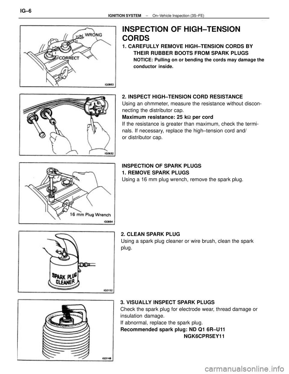
2. INSPECT HIGH±TENSION CORD RESISTANCE
Using an ohmmeter, measure the resistance without discon-
necting the distributor cap.
Maximum resistance: 25 k
� per cord
If the resistance is greater than maximum, check the termi-
nals. If necessary, replace the high±tension cord and/
or distributor cap.
3. VISUALLY INSPECT SPARK PLUGS
Check the spark plug for electrode wear, thread damage or
insulation damage.
If abnormal, replace the spark plug.
Recommended spark plug: ND Q1 6R±U11
NGK6CPR5EY11
INSPECTION OF HIGH±TENSION
CORDS
1. CAREFULLY REMOVE HIGH±TENSION CORDS BY
THEIR RUBBER BOOTS FROM SPARK PLUGS
NOTICE: Pulling on or bending the cords may damage the
conductor inside.
INSPECTION OF SPARK PLUGS
1. REMOVE SPARK PLUGS
Using a 16 mm plug wrench, remove the spark plug.
2. CLEAN SPARK PLUG
Using a spark plug cleaner or wire brush, clean the spark
plug.
± IGNITION SYSTEMOn±Vehicle Inspection (3S±FE)IG±6
Page 1840 of 2389
 or more
If the air gap is not as spe")
INSPECTION OF DISTRIBUTOR
1. INSPECT AIR GAP
Using a feeler gauge, measure the gap between the signal
rotor and pickup coil projection.
Air gap: 0.2 mm (0.008 in.) or more
If the air gap is not as specified, replace the distributor
housing assembly.INSPECTION OF IGNITION COIL
1. INSPECT PRIMARY COIL RESISTANCE
Using an ohmmeter, measure the resistance between posi-
tive (+) and negative (±) terminals.
Primary coil resistance (Cold): 0.38 ± 0.46�
If the resistance is not as specified, replace the ignition coil.
2. INSPECT SECONDARY COIL RESISTANCE
Using an ohmmeter, measure the resistance between the
positive (+) and high±tension terminals.
Secondary coil resistance (Cold): 7.7 ±10.4 k
�
If the resistance is not as specified, replace the ignition coil.4. ADJUST ELECTRODE GAP
Carefully bend the outer electrode to obtain the correct elec-
trode gap.
Correct electrode plug: 1.1 mm (0.043 in.)
5. INSTALL SPARK PLUGS
Using a 16 mm plug wrench, install the spark plug.
Torque: 180 kg±cm (13 ft±lb, 18 N±m)
± IGNITION SYSTEMOn±Vehicle Inspection (3S±FE)IG±7
Page 1843 of 2389
.
6.")
INSPECTION OF SPARK PLUGS
NOTICE:
wNever use a wire brush for cleaning
wNever attempt to adjust the electrode gap on used
spark plug.
wSpark plug should be replaced every 100,000 km
I60,000 miles).
6. If not using a megger:
(a) Quickly race the engine to 4,000 rpm five times.
(b) Remove the spark plug.
(See step 2 on page IG±11)
(C) Visually check the spark plug.
If the electrode is dry ... Okay
If the electrode is wet ... Proceed to step 3 INSPECTION OF HIGH±TENSION CORDS
1. CAREFULLY REMOVE HIGH±TENSION CORDS BY
THEIR RUBBER BOOTS FROM SPARK PLUGS
NOTICE: Pulling on or bending the cords may damage the
conductor inside.
1. INSPECT ELECTRODE
A. If using a megger (insulation resistance motor):
Measure the insulation resistance.
Correct insulation resistance: 10 M
� or more
If the resistance is less than specified, proceed step 2. 2. INSPECT HIGH±TENSION CORD RESISTANCE
Using an ohmmeter, measure the resistance.
Maximum resistance: 25 k
� per cord
If the resistance is greater than maximum, replace the high±
tension cord.
± IGNITION SYSTEMOn±Vehicle Inspection (2VZ±FE)IG±10
Page 1844 of 2389

If the gap is greater than maximum, replace the spark plug.
Correct electrode gap of new spark plug:
1.1 mm (0.043 in.)
If adjustin")
4. INSPECT ELECTRODE GAP
Maximum electrode gap: 1.3 mm, (0.051 in.)
If the gap is greater than maximum, replace the spark plug.
Correct electrode gap of new spark plug:
1.1 mm (0.043 in.)
If adjusting the gap of a new spark plug, bend only the base
of the ground electrode. Do not touch the tip.
5. CLEAN SPARK PLUGS
If the electrode has traces of wet carbon, allow it to dry and
then clean with a spark plug cleaner.
Air pressure: Below6 kg/cm
2 (85 psi, 588 kPa)
Duration: 20 seconds or less
HINT: If there are traces of oil, remove it with gasoline before
using the spark plug cleaner.3. VISUALLY INSPECT SPARK PLUGS
Check the spark plug for thread or insulation damage.
If abnormal, replace the spark plug.
Recommended spark plug: ND PQ2OR
NGK6CPR6EP11
6. INSTALL SPARK PLUGS
Using a 16 mm plug wrench, install and torque the spark
plug.
Torque: 180 kg±cm (13 ft±Lb, 18 N±m)
2. REMOVE SPARK PLUGS
Using a 16 mm plug wrench, remove the spark plug.
± IGNITION SYSTEMOn±Vehicle Inspection (2VZ±FE)IG±11
Page 1846 of 2389
REMOVAL OF DISTRIBUTOR
1. DISCONNECT CABLE FROM NEGATIVE TERMINAL
OF BATTERY
2. REMOVE AIR CLEANER HOSE
3. DISCONNECT DISTRIBUTOR CONNECTORS
4. DISCONNECT HIGH±TENSION CORDS FROM SPARK
PLUGS
5. REMOVE DISTRIBUTOR
Remove the two hold±down bolts and pull out the distributor.
Remove the 0±ring.
DISTRIBUTOR (3S±FE)
COMPONENTS
± IGNITION SYSTEMDistributor (3S±FE)IG±13
Page 1849 of 2389

3. CONNECT HIGH±TENSION CORDS TO SPARK PLUGS
Firing order: 1 ± 3 ± 4 ± Z
4. CONNECT DISTRIBUTOR CONNECTORS
5. INSTALL AIR CLEANER HOSE
6. CONNECT CABLE TO NEGATIVE TERMINAL OF
BATTERY
7. WARM UP ENGINE
Allow the engine to normal operating temperature.
8. CONNECT TACHOMETER AND TIMING LIGHT TO
ENGINE ±
Connect the test probe of a tachometer to the service con-
nector of the distributor.
NOTICE:
wNEVER allow the tachometer test probe to touch ground
as it could result in damage to the igniter and/or ignition
coil.
wAs some tachometers are not compatible with this igni-
tion system, we recommend that you confirm the
compatibility of your unit before use. (c) Align the cutout of the coupling with the line of the
housing.
(d) Insert the distributor, aligning the center of the flange
with that of bolt hole on the cylinder head.
(e) Lightly tighten the two hold±down bolts. INSTALLATION OF DISTRIBUTOR
1. SET NO.1 CYLINDER TO TDC/COMPRESSION
Turn the crankshaft clockwise, and position the slit of the
intake camshaft as shown.
2. INSTALL DISTRIBUTOR
(a) Install a new 0±ring to the housing.
(b) Apply a light coat of engine oil on the 0±ring.
± IGNITION SYSTEMDistributor PS±FE)IG±16
Page 1912 of 2389
 or asterisk (*) are required under the terms of the Emission Control Systems Warranty. See Owners Guide or Warranty Booklet
for complete warranty informat")
Maintenance services indicated by a star (*) or asterisk (*) are required under the terms of the Emission Control Systems Warranty. See Owner's Guide or Warranty Booklet
for complete warranty information.
* For vehicles sold in California
* For vehicles sold outside California
(1) Applicable to vehicles operated under conditions of extensive idling and /or low speed driving for long distances such as police, taxi or door±to±door delivery use.
(2) Applicable when operating mainly on dusty roads. If not, follow SCHEDULE B.
(3) Includes inspection of fuel tank band and vapor vent system.
(4) Also applicable to lining drum for parking brake.
(5) Check for leakage.
(6) Check for oil leaks from steering gear housing.
(7) Applicable only when operating mainly on rough, muddy roads. The applicable parts are listed below. For other usage conditions, refer to SCHEDULE B.
w
Front and rear suspension member to body
w
0 Strut bar bracket to body bolts
w
Bolts for sheet installation
MAINTENANCE SCHEDULESCHEDULE A
CONDITIONS:
wTowing a trailer, using a camper or car top carrier.
wRepeated short trips less than 5 miles (8 km) and outside temperatures remain below freezing.
wExtensive idling and/or low speed driving for a long distance such as police, taxi or door±to±door delivery use.
wOperating on dusty, rough, muddy or salt spread roads.Maintenance operations: A = Check and adjust if necessary;
R = Replace, change or lubricate;
I = Inspect and correct or replace if necessary
Maintenance services beyond 60,000 miles (96,000 km) should continue to be performed at the same intervals shown for each
maintenance schedule.
Service interval
(Odometer reading or
months, whichever
comes first)
Maintenance items
Manual transaxle, automatic transaxle
and differential Brake pads and discs (Front and rear)
Bolts and nuts on chassis and bodyExhaust pipes and mountings
Steering gear housing oily Brake line pipes and hosesFuel lines and connections
Ball joints and dust coversEngine oil and oil filter
Spark plugs (platinum tipped)MA±4 (item 2)
MA±6 (item 6)
Brake linings and drumsFuel tank cap gasket
Drive shaft boots
MA±14 item 221 MA±10 (item 20) MA±5 (item 3,4)
Steering linkageMA±7 (item 12)
MA±8 (item 14) Valve clearance
MA±8 (item 16)
MA±9 (item 19) MA±7 (item 13) MA±7 (item 11
MA±7 (item 10)
MA±9 (item 18) Charcoal canister
MA±9 (item 17) MA±8 (item 151
See page
(item No.)
Engine coolant
MA±6 (item 9) MA±4 (item 1)
MA±4 (item 2)
MA±5 (item 5)
MA±8 (item 8) AAA±6 (item 7)
Air filter¿21*
Spark plugsTiming belt
Drive belts
IGNITION
CHASSIS BRAKESENGINESystem
EVAP FUEL
± MAINTENANCEMaintenance ScheduleMA±2