Page 1209 of 2389
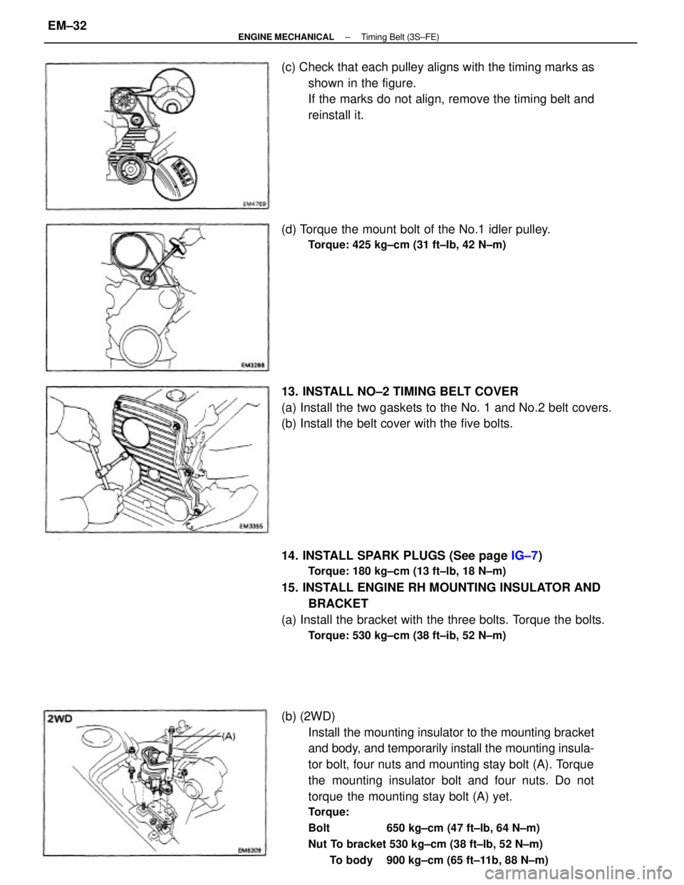
(b) (2WD)
Install the mounting insulator to the mounting bracket
and body, and temporarily install the mounting insula-
tor bolt, four nuts and mounting stay bolt (A). Torque
the mounting insulator bolt and four nuts. Do not
torque the mounting stay bolt (A) yet.
Torque:
Bolt 650 kg±cm (47 ft±lb, 64 N±m)
Nut To bracket 530 kg±cm (38 ft±lb, 52 N±m)
To body 900 kg±cm (65 ft±11b, 88 N±m)
14. INSTALL SPARK PLUGS (See page IG±7)
Torque: 180 kg±cm (13 ft±lb, 18 N±m)
15. INSTALL ENGINE RH MOUNTING INSULATOR AND
BRACKET
(a) Install the bracket with the three bolts. Torque the bolts.
Torque: 530 kg±cm (38 ft±ib, 52 N±m)
13. INSTALL NO±2 TIMING BELT COVER
(a) Install the two gaskets to the No. 1 and No.2 belt covers.
(b) Install the belt cover with the five bolts. (c) Check that each pulley aligns with the timing marks as
shown in the figure.
If the marks do not align, remove the timing belt and
reinstall it.
(d) Torque the mount bolt of the No.1 idler pulley.
Torque: 425 kg±cm (31 ft±Ib, 42 N±m)
± ENGINE MECHANICALTiming Belt (3S±FE)EM±32
Page 1212 of 2389
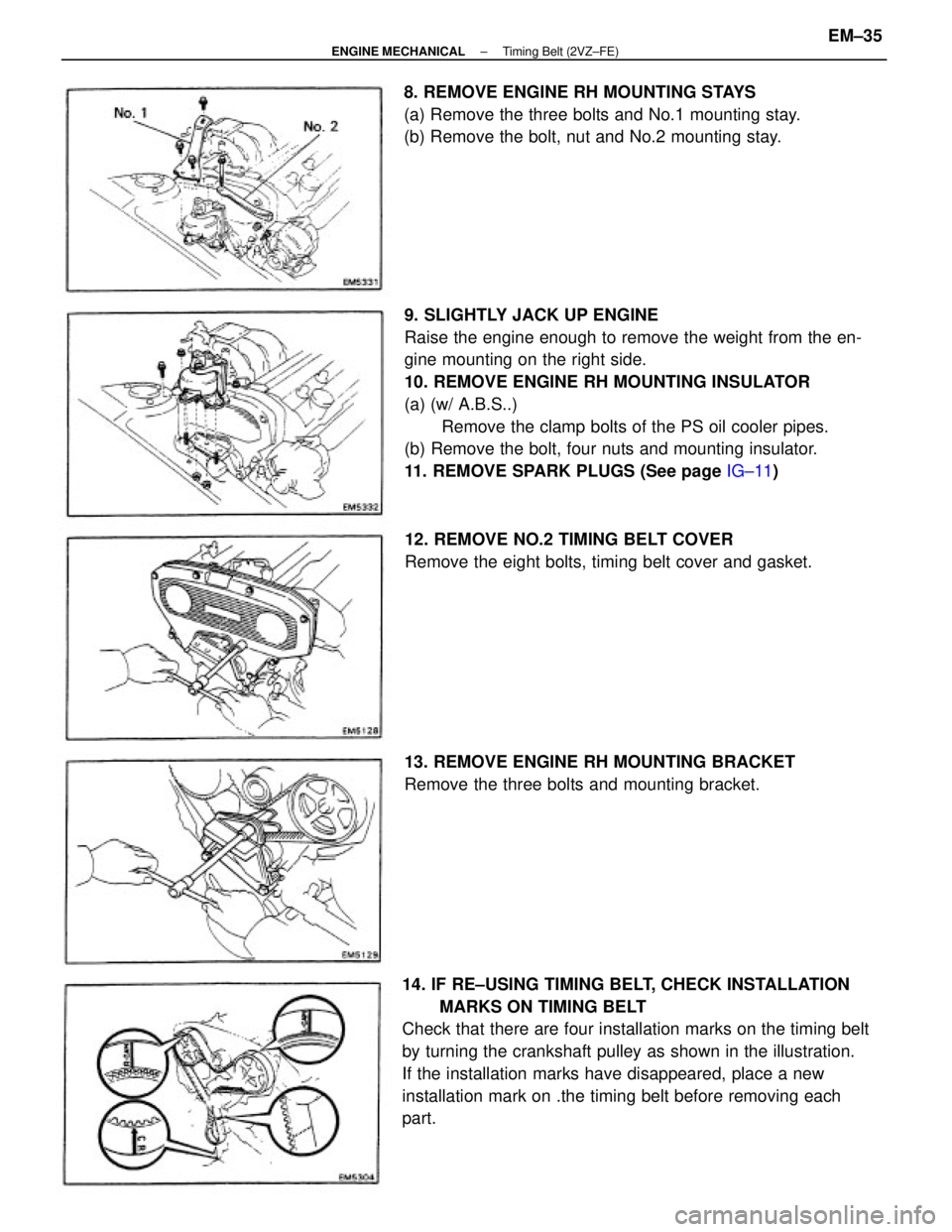
9. SLIGHTLY JACK UP ENGINE
Raise the engine enough to remove the weight from the en-
gine mounting on the right side.
10. REMOVE ENGINE RH MOUNTING INSULATOR
(a) (w/ A.B.S..)
Remove the clamp bolts of the PS oil cooler pipes.
(b) Remove the bolt, four nuts and mounting insulator.
11. REMOVE SPARK PLUGS (See page IG±11)
14. IF RE±USING TIMING BELT, CHECK INSTALLATION
MARKS ON TIMING BELT
Check that there are four installation marks on the timing belt
by turning the crankshaft pulley as shown in the illustration.
If the installation marks have disappeared, place a new
installation mark on .the timing belt before removing each
part.8. REMOVE ENGINE RH MOUNTING STAYS
(a) Remove the three bolts and No.1 mounting stay.
(b) Remove the bolt, nut and No.2 mounting stay.
12. REMOVE NO.2 TIMING BELT COVER
Remove the eight bolts, timing belt cover and gasket.
13. REMOVE ENGINE RH MOUNTING BRACKET
Remove the three bolts and mounting bracket.
± ENGINE MECHANICALTiming Belt (2VZ±FE)EM±35
Page 1223 of 2389
16. INSTALL NO.2 TIMING BELT COVER
(a) Install the gasket to the timing belt cover.
(b) Install the timing belt cover with the eight bolts.
HINT: Use the bolts indicated by A, B and C.
17. INSTALL SPARK PLUGS (See page IG±11 )
Torque: 180 k9±cm (13 ft±Ib, 18 N±m)
14. CHECK VALVE TIMING
(a) Turn the crankshaft pulley two revolutions from TDC
to TDC.
HINT: Always turn the crankshaft clockwise.
(b) Check that each pulley aligns with the timing marks as
shown in the figure.
If the marks do not align, remove the timing belt and
reinstall it.
15. INSTALL ENGINE RH MOUNTING BRACKET
Install the mounting bracket with the three bolt.
Torque: 410 kg±cm (30 ft±lb, 39 N±m)
(b) Remove the 1.27 mm hexagon wrench (sized 1.27
mm) from the tensioner.
± ENGINE MECHANICALTiming Belt (2VZ±FE)EM±46
Page 1229 of 2389
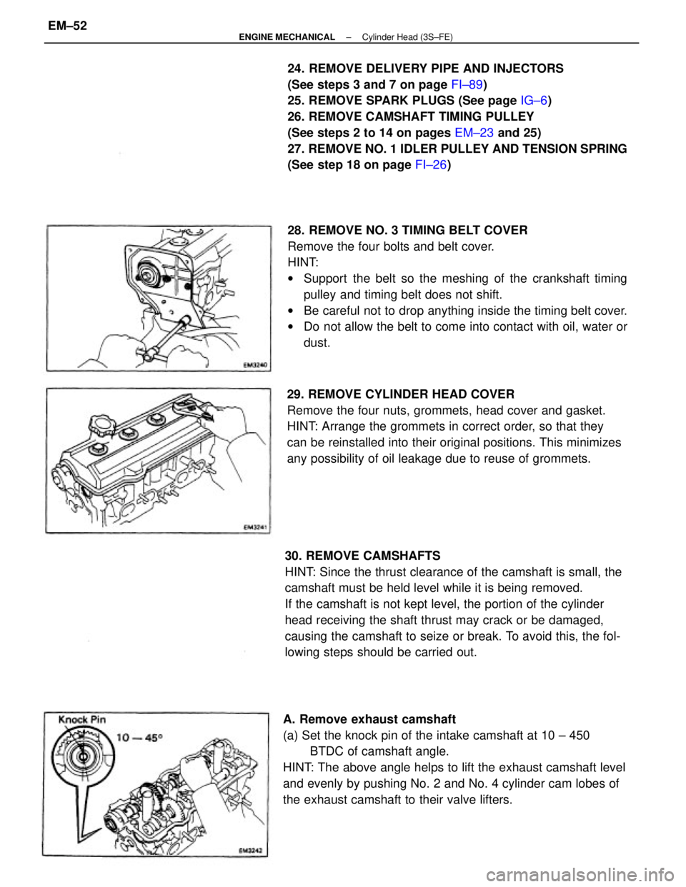
28. REMOVE NO. 3 TIMING BELT COVER
Remove the four bolts and belt cover.
HINT:
wSupport the belt so the meshing of the crankshaft timing
pulley and timing belt does not shift.
wBe careful not to drop anything inside the timing belt cover.
wDo not allow the belt to come into contact with oil, water or
dust. 24. REMOVE DELIVERY PIPE AND INJECTORS
(See steps 3 and 7 on page FI±89)
25. REMOVE SPARK PLUGS (See page IG±6)
26. REMOVE CAMSHAFT TIMING PULLEY
(See steps 2 to 14 on pages EM±23 and 25)
27. REMOVE NO. 1 IDLER PULLEY AND TENSION SPRING
(See step 18 on page FI±26)
30. REMOVE CAMSHAFTS
HINT: Since the thrust clearance of the camshaft is small, the
camshaft must be held level while it is being removed.
If the camshaft is not kept level, the portion of the cylinder
head receiving the shaft thrust may crack or be damaged,
causing the camshaft to seize or break. To avoid this, the fol-
lowing steps should be carried out.
A. Remove exhaust camshaft
(a) Set the knock pin of the intake camshaft at 10 ± 450
BTDC of camshaft angle.
HINT: The above angle helps to lift the exhaust camshaft level
and evenly by pushing No. 2 and No. 4 cylinder cam lobes of
the exhaust camshaft to their valve lifters.29. REMOVE CYLINDER HEAD COVER
Remove the four nuts, grommets, head cover and gasket.
HINT: Arrange the grommets in correct order, so that they
can be reinstalled into their original positions. This minimizes
any possibility of oil leakage due to reuse of grommets.
± ENGINE MECHANICALCylinder Head (3S±FE)EM±52
Page 1248 of 2389
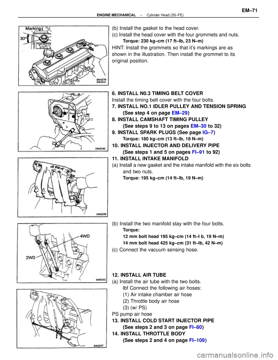
6. INSTALL N0.3 TIMING BELT COVER
Install the timing belt cover with the four bolts.
7. INSTALL NO.1 IDLER PULLEY AND TENSION SPRING
(See step 4 on page EM±29)
8. INSTALL CAMSHAFT TIMING PULLEY
(See steps 9 to 13 on pages EM±30 to 32)
9. INSTALL SPARK PLUGS (See page IG±7)
Torque: 180 kg±cm (13 ft±lb, 18 N±m)
10. INSTALL INJECTOR AND DELIVERY PIPE
(See steps 1 and 5 on pages FI±91 to 92)
11. INSTALL INTAKE MANIFOLD
(a) Install a new gasket and the intake manifold with the six bolts
and two nuts.
Torque: 195 kg±cm (14 ft±lb, 19 N±m)
12. INSTALL AIR TUBE
(a) Install the air tube with the two bolts.
lbf Connect the following air hoses:
(1) Air intake chamber air hose
(2) Throttle body air hose
(3) (w/ PS)
PS pump air hose
13. INSTALL COLD START INJECTOR PIPE
(See steps 2 and 3 on page FI±80)
14. INSTALL THROTTLE BODY
(See steps 2 and 4 on page FI±109) (b) Install the gasket to the head cover.
(c) Install the head cover with the four grommets and nuts.
Torque: 230 kg±cm (17 ft±Ib, 23 N±m)
HINT: Install the grommets so that it's markings are as
shown in the illustration. Then install the grommet to its
original position.
(b) Install the two manifold stay with the four bolts.
Torque:
12 mm bolt head 195 kg±cm (14 ft±I b, 19 N±m)
14 mm bolt head 425 kg±cm (31 ft±lb, 42 N±m)
(c) Connect the vacuum sensing hose.
± ENGINE MECHANICALCylinder Head (3S±FE)EM±71
Page 1256 of 2389
31. REMOVE NO.3 TIMING BELT COVER
Remove the six bolts and timing belt cover.
NOTICE:
wSupport the belt so the meshing of the crankshaft
timing pulley and timing belt does not shift.
wBe careful not to drop anything inside the timing belt cover.
wDo not allow the belt to come into contact with oil, water or
dust. (b) Remove the six nuts, exhaust manifold and gasket.
29. REMOVE SPARK PLUGS (See page IG±11)
30. REMOVE TIMING BELT, CAMSHAFT TIMING
PULLEYS AND No.2 IDLER PULLEY
(See steps 3 to 19 on pages EM±34 to 37) 28. REMOVE LH EXHAUST MANIFOLD
(a) Remove the two nuts and heat insulator. (c) Remove the six nuts, exhaust manifold and gasket.
(d) Remove the bolt and inside heat insulator.
± ENGINE MECHANICALCylinder Heads (2VZ±FE)EM±79
Page 1279 of 2389
9. INSTALL NO.3 TIMING BELT COVER
Install the timing belt cover. with the six bolts.
Torque: 75 kg±cm (65 in.±lb, 7.4 N±m)
10. INSTALL NO.2 IDLER PULLEY, CAMSHAFT TIMING
PULLEYS AND TIMING BELT
(See steps 7 to 26 on pages EM±43 to 47)
11. INSTALL SPARK PLUGS (See page IG±11)
Torque: 180kg±cm (13 ft±Ib, 18 N±m)
8. INSTALL CYLINDER HEAD COVERS
(a) Apply seal packing to the cylinder heads as shown in the fig-
ure.
Seal packing: Part No.08826±00080 or equivalent
(b) Install the gasket to the cylinder head cover.
(c) Install the cylinder head cover with the six seal washers
and nuts. Install the two cylinder head covers.
Torque: 60 kg±cm (5Z in.±Ib, 5.9 N±m)
12. INSTALL RH EXHAUST MANIFOLD
(a) Install the inside heat insulator with the bolt.
± ENGINE MECHANICALCylinder Heads (2VZ±FE)EM±102
Page 1836 of 2389
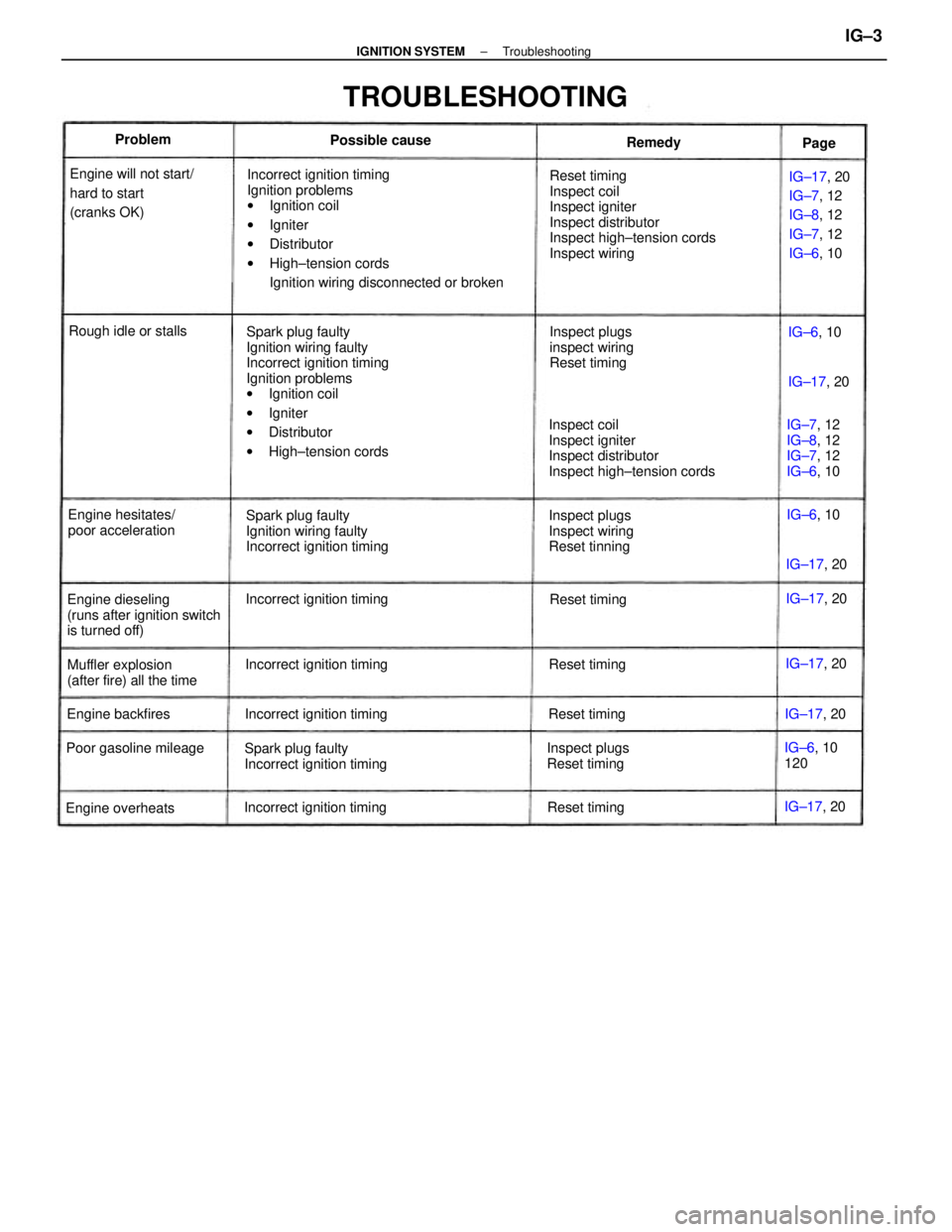
Incorrect ignition timing
Ignition problems
wIgnition coil
wIgniter
wDistributor
wHigh±tension cords
Ignition wiring disconnected or broken
Spark plug faulty
Ignition wiring faulty
Incorrect ignition timing
Ignition problems
wIgnition coil
wIgniter
wDistributor
wHigh±tension cordsReset timing
Inspect coil
Inspect igniter
Inspect distributor
Inspect high±tension cords
Inspect wiring
Inspect coil
Inspect igniter
Inspect distributor
Inspect high±tension cords
Spark plug faulty
Ignition wiring faulty
Incorrect ignition timingIG±17, 20
IG±7, 12
IG±8, 12
IG±7, 12
IG±6, 10
Spark plug faulty
Incorrect ignition timing Engine will not start/
hard to start
(cranks OK)
TROUBLESHOOTING
Engine dieseling
(runs after ignition switch
is turned off)Inspect plugs
Inspect wiring
Reset tinningInspect plugs
inspect wiring
Reset timing
Muffler explosion
(after fire) all the timeEngine hesitates/
poor accelerationIG±7, 12
IG±8, 12
IG±7, 12
IG±6, 10
Inspect plugs
Reset timing Incorrect ignition timing
Incorrect ignition timing
Incorrect ignition timing
Incorrect ignition timing Poor gasoline mileageRough idle or stalls
IG±6, 10
120
Engine overheatsEngine backfiresPossible cause
Reset timing
Reset timingReset timingReset timingIG±17, 20 IG±17, 20
IG±17, 20
IG±17, 20 IG±17, 20
IG±17, 20 Problem
IG±6, 10
IG±6, 10 Remedy
Page
± IGNITION SYSTEMTroubleshootingIG±3