Page 1434 of 2389

Example:
Back of the
Connector Body
P/N 90980±10854
B±5
TERMINAL AND CONNECTOR REPAIR±TERMINAL REPLACEMENT
15
Wire Harness Repair Manual (RM1022E)
NOTICE:
�When the terminal used is gold plated, be sure to
replace it with a gold plated terminal when marking
repairs.
�Do not use male and female terminals which are
made of different materials from each other.
2. Connector Body
(a)Identify the part number of the corresponding
terminal with wire according to the above±mentioned
1.
(b)Identify the part number of the connector body by
picking out the correct one from the illustrations
according to the number of terminals and the shape.
HINT:
(a)If you can find no connector which matches the type
you require, pick out male and female connector
bodies as a set which have more terminals than you
require.
For the combined terminal type connector body, pick
out and appropriate connector body for each terminal
being used.
Example:
When two types of terminal are used in one connector
body, pick out a male and female for two different
connector bodies.
(b)The part number has been stamped on the back of
the connector body. (This will continue to be done to
new types of connector.)
B
Page 1435 of 2389
Hole Plug
Connector Body
Terminal
Packing
Small (Red)
Large (Yellow) Medium (Blue)
Medium (Blue) 1.0±2.0 mm
Large (Yellow) 3.0±5.0 mmWire Outside
DiameterSleeve Size
(Color)
Small (Red) 0.2±1.0 mm
Wire Outside Diameter
Insulation Calipers
TERMINAL AND CONNECTOR REPAIR±TERMINAL REPLACEMENT
B±6
16
Wire Harness Repair Manual (RM1022E)
3. Hole Plug/Terminal Packing
(a)Identify the part number of the appropriate terminal
with wire/connector body from the illustrations of
waterproof type connector according to the
above±mentioned 1 and 2.
(b)Identify the part number of the hole plug/terminal
packing from the corresponding illustration.
4. Sleeve
When connecting two wires using a sleeve, select the
sleeve according to the following table.
(a)When size is based on the outside diameter of the
wire.
B
Page 1454 of 2389
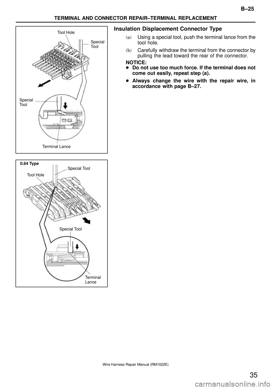
Tool Hole
Terminal LanceSpecial
Tool
Special
Tool
Tool HoleSpecial Tool
Terminal
Lance Special Tool 0.64 Type
B±25
TERMINAL AND CONNECTOR REPAIR±TERMINAL REPLACEMENT
35
Wire Harness Repair Manual (RM1022E)
Insulation Displacement Connector Type
(a)Using a special tool, push the terminal lance from the
tool hole.
(b)Carefully withdraw the terminal from the connector by
pulling the lead toward the rear of the connector.
NOTICE:
�Do not use too much force. If the terminal does not
come out easily, repeat step (a).
�Always change the wire with the repair wire, in
accordance with page B±27.
Page 1814 of 2389
F±17
TABLE OF REPAIR WIRE, TERMINAL PACKING, HOLE PLUG AND PRESS SLEEVE
Wire Harness Repair Manual (RM1022E)
395
Repair Wire (Non±waterproof Type)
TypeSP
Female (Power)Female (Signal)
Sleeve : Medium (Blue) or Large (Yellow)Sleeve : Medium (Blue) or Large (Yellow)
P/N82998±1252082998±12530
TypeTLC
MaleFemale
Sleeve : Medium (Blue)Sleeve : Medium (Blue)
P/N82998±1222082998±12230
TypeTNS
MaleFemale
Sleeve : Medium (Blue)Sleeve : Medium (Blue)
P/N82998±1224082998±12250
Page 1836 of 2389
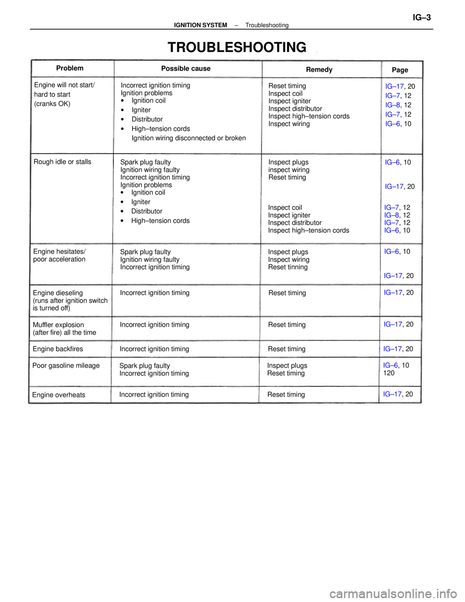
Incorrect ignition timing
Ignition problems
wIgnition coil
wIgniter
wDistributor
wHigh±tension cords
Ignition wiring disconnected or broken
Spark plug faulty
Ignition wiring faulty
Incorrect ignition timing
Ignition problems
wIgnition coil
wIgniter
wDistributor
wHigh±tension cordsReset timing
Inspect coil
Inspect igniter
Inspect distributor
Inspect high±tension cords
Inspect wiring
Inspect coil
Inspect igniter
Inspect distributor
Inspect high±tension cords
Spark plug faulty
Ignition wiring faulty
Incorrect ignition timingIG±17, 20
IG±7, 12
IG±8, 12
IG±7, 12
IG±6, 10
Spark plug faulty
Incorrect ignition timing Engine will not start/
hard to start
(cranks OK)
TROUBLESHOOTING
Engine dieseling
(runs after ignition switch
is turned off)Inspect plugs
Inspect wiring
Reset tinningInspect plugs
inspect wiring
Reset timing
Muffler explosion
(after fire) all the timeEngine hesitates/
poor accelerationIG±7, 12
IG±8, 12
IG±7, 12
IG±6, 10
Inspect plugs
Reset timing Incorrect ignition timing
Incorrect ignition timing
Incorrect ignition timing
Incorrect ignition timing Poor gasoline mileageRough idle or stalls
IG±6, 10
120
Engine overheatsEngine backfiresPossible cause
Reset timing
Reset timingReset timingReset timingIG±17, 20 IG±17, 20
IG±17, 20
IG±17, 20 IG±17, 20
IG±17, 20 Problem
IG±6, 10
IG±6, 10 Remedy
Page
± IGNITION SYSTEMTroubleshootingIG±3
Page 1914 of 2389
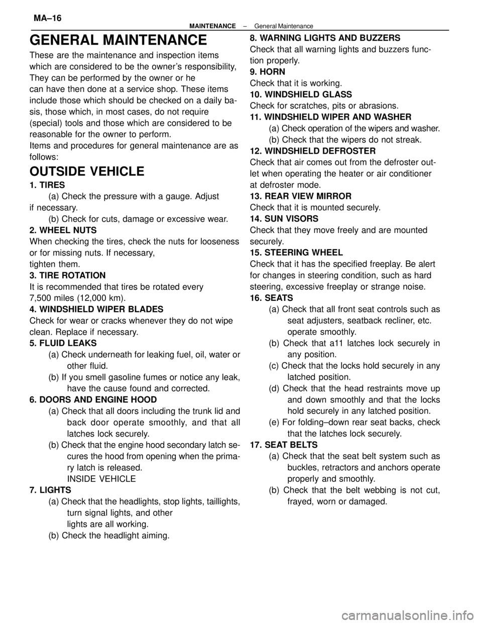
GENERAL MAINTENANCE
These are the maintenance and inspection items
which are considered to be the owner's responsibility,
They can be performed by the owner or he
can have then done at a service shop. These items
include those which should be checked on a daily ba-
sis, those which, in most cases, do not require
(special) tools and those which are considered to be
reasonable for the owner to perform.
Items and procedures for general maintenance are as
follows:
OUTSIDE VEHICLE
1. TIRES
(a) Check the pressure with a gauge. Adjust
if necessary.
(b) Check for cuts, damage or excessive wear.
2. WHEEL NUTS
When checking the tires, check the nuts for looseness
or for missing nuts. If necessary,
tighten them.
3. TIRE ROTATION
It is recommended that tires be rotated every
7,500 miles (12,000 km).
4. WINDSHIELD WIPER BLADES
Check for wear or cracks whenever they do not wipe
clean. Replace if necessary.
5. FLUID LEAKS
(a) Check underneath for leaking fuel, oil, water or
other fluid.
(b) If you smell gasoline fumes or notice any leak,
have the cause found and corrected.
6. DOORS AND ENGINE HOOD
(a) Check that all doors including the trunk lid and
back door operate smoothly, and that all
latches lock securely.
(b) Check that the engine hood secondary latch se-
cures the hood from opening when the prima-
ry latch is released.
INSIDE VEHICLE
7. LIGHTS
(a) Check that the headlights, stop lights, taillights,
turn signal lights, and other
lights are all working.
(b) Check the headlight aiming.8. WARNING LIGHTS AND BUZZERS
Check that all warning lights and buzzers func-
tion properly.
9. HORN
Check that it is working.
10. WINDSHIELD GLASS
Check for scratches, pits or abrasions.
11. WINDSHIELD WIPER AND WASHER
(a) Check operation of the wipers and washer.
(b) Check that the wipers do not streak.
12. WINDSHIELD DEFROSTER
Check that air comes out from the defroster out-
let when operating the heater or air conditioner
at defroster mode.
13. REAR VIEW MIRROR
Check that it is mounted securely.
14. SUN VISORS
Check that they move freely and are mounted
securely.
15. STEERING WHEEL
Check that it has the specified freeplay. Be alert
for changes in steering condition, such as hard
steering, excessive freeplay or strange noise.
16. SEATS
(a) Check that all front seat controls such as
seat adjusters, seatback recliner, etc.
operate smoothly.
(b) Check that a11 latches lock securely in
any position.
(c) Check that the locks hold securely in any
latched position.
(d) Check that the head restraints move up
and down smoothly and that the locks
hold securely in any latched position.
(e) For folding±down rear seat backs, check
that the latches lock securely.
17. SEAT BELTS
(a) Check that the seat belt system such as
buckles, retractors and anchors operate
properly and smoothly.
(b) Check that the belt webbing is not cut,
frayed, worn or damaged.
± MAINTENANCEGeneral MaintenanceMA±16
Page 1927 of 2389
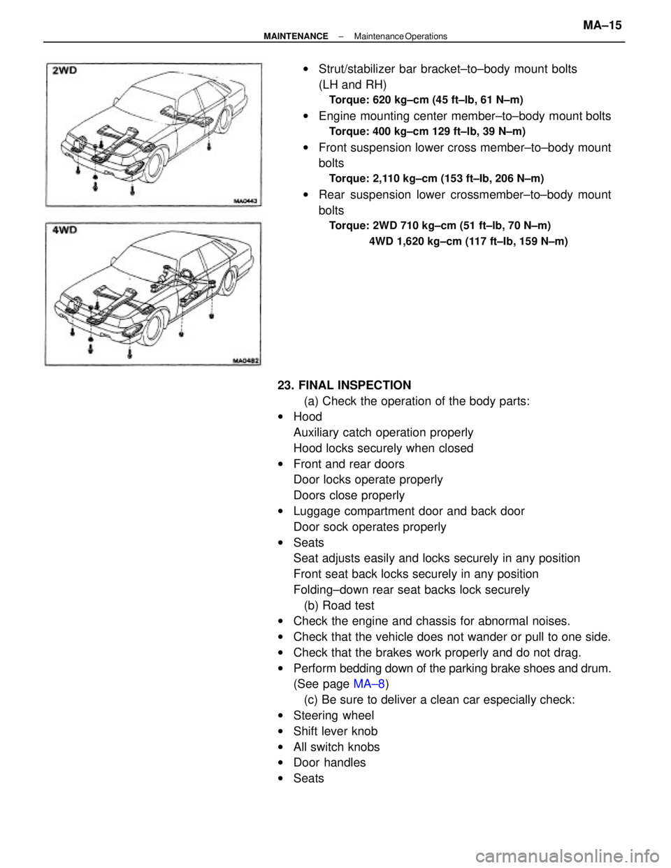
23. FINAL INSPECTION
(a) Check the operation of the body parts:
wHood
Auxiliary catch operation properly
Hood locks securely when closed
wFront and rear doors
Door locks operate properly
Doors close properly
wLuggage compartment door and back door
Door sock operates properly
wSeats
Seat adjusts easily and locks securely in any position
Front seat back locks securely in any position
Folding±down rear seat backs lock securely
(b) Road test
wCheck the engine and chassis for abnormal noises.
wCheck that the vehicle does not wander or pull to one side.
wCheck that the brakes work properly and do not drag.
wPerform bedding down of the parking brake shoes and drum.
(See page MA±8)
(c) Be sure to deliver a clean car especially check:
wSteering wheel
wShift lever knob
wAll switch knobs
wDoor handles
wSeatswStrut/stabilizer bar bracket±to±body mount bolts
(LH and RH)
Torque: 620 kg±cm (45 ft±lb, 61 N±m)
wEngine mounting center member±to±body mount bolts
Torque: 400 kg±cm 129 ft±lb, 39 N±m)
wFront suspension lower cross member±to±body mount
bolts
Torque: 2,110 kg±cm (153 ft±Ib, 206 N±m)
wRear suspension lower crossmember±to±body mount
bolts
Torque: 2WD 710 kg±cm (51 ft±lb, 70 N±m)
4WD 1,620 kg±cm (117 ft±Ib, 159 N±m)
± MAINTENANCEMaintenance OperationsMA±15
Page 2188 of 2389
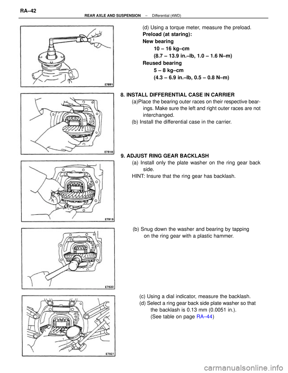
(d) Using a torque meter, measure the preload.
Preload (at staring):
New bearing
10 ± 16 kg±cm
(8.7 ± 13.9 in.±Ib, 1.0 ± 1.6 N±m)
Reused bearing
5 ± 8 kg±cm
(4.3 ± 6.9 in.±Ib, 0.5 ± 0.8 N±m)
9. ADJUST RING GEAR BACKLASH
(a) Install only the plate washer on the ring gear back
side.
HINT: Insure that the ring gear has backlash. 8. INSTALL DIFFERENTIAL CASE IN CARRIER
(a)Place the bearing outer races on their respective bear-
ings. Make sure the left and right outer races are not
interchanged.
(b) Install the differential case in the carrier.
(c) Using a dial indicator, measure the backlash.
(d) Select a ring gear back side plate washer so that
the backlash is 0.13 mm (0.0051 in.).
(See table on page RA±44) (b) Snug down the washer and bearing by tapping
on the ring gear with a plastic hammer.
± REAR AXLE AND SUSPENSIONDifferential (4WD)RA±42