Page 993 of 2389
REMOVAL OF WATER PUMP
1. DRAIN ENGINE COOLANT (See page CO±4)
2. DISCONNECT WATER TEMPERATURE SWITCH
CONNECTOR
3. DISCONNECT RADIATOR LOWER HOSE FROM
WATER INLET HOUSING
4. REMOVE TIMING BELT, PULLEYS
(See pages EM±23 to 26)
5. REMOVE WATER PUMP AND WATER PUMP COVER
ASSEMBLY .
(a) Remove the two nuts holding the pump to the water by±
pass pipe.
WATER PUMP (3S±FE)
COMPONENTS
± COOLING SYSTEMWater Pump (3S±FE)CO±6
Page 995 of 2389
(b) Apply a fight coat of engine oil on the 4±ring of the water
by±pass pipe.
(c) Connect the pump cover to the water by±pass pipe. Do
not install the nuts yet.
(d) Install the water pump with the three bolts. Torque the
bolts in the sequence shown.
Torque: 95 kg±cm (82 in.±Ib, 9.3 N±m)
3. INSTALL PULLEYS AND TIMING BELT (See pages
EM±29 to 33)
4. CONNECT RADIATOR LOWER HOSE
5. CONNECT WATER TEMPERATURE SWITCH
CONNECTOR
6. FILL WITH ENGINE COOLANT (See page CO±5) (e) Install the two nuts holding the pump cover to the water
by±pass pipe.
Torque: 95 kg±cm (82 in.±Ib, 9.3 N±m)
± COOLING SYSTEMWater Pump PS±FE)CO±8
Page 996 of 2389
REMOVAL OF WATER PUMP
1. DRAIN ENGINE COOLANT (See page CO±5)
2. DISCONNECT RADIATOR LOWER NOSE FROM
WATER INLET PIPE
3. DISCONNECT TIMING BELT FROM WATER PUMP
PULLEY (See pages EM±34 to 39)
4. REMOVE WATER INLET PIPE
(a) Remove the bolt holding the water inlet pipe to the alternator
belt adjusting bar.
(b) Remove the water inlet pipe and 0±ring.
5. REMOVE WATER INLET AND THERMOSTAT
(See steps 4 and 5 on page CO±13)
WATER PUMP(2VZ±FE)
COMPONENTS
± COOLING SYSTEMWater Pump (2VZ±FE)CO±9
Page 998 of 2389
3. INSTALL WATER INLET PIPE
(a) Install a new 0±ring to the water inlet pipe.
(b) Apply soapy water to the O±ring.
(c) Connect the water inlet pipe to the water inlet.
(d) Install the bolt holding the water inlet pipe to the alternator
belt adjusting bar.
Torque: 200 kg±cm (14 ft±Ib, 20 N±m)
4. INSTALL TIMING BELT (See pages EM±42 to 46)
5. CONNECT RADIATOR LOWER HOSE
6. FILL WITH ENGINE COOLANT (See page CO±5)
± COOLING SYSTEMWater Pump (2VZ±FE)CO±11
Page 999 of 2389

THERMOSTAT (3S±FE)
REMOVAL OF THERMOSTAT
1. DRAIN ENGINE COOLANT (See page CO±4)
2. DISCONNECT WATER TEMPERATURE SWITCH
CONNECTOR
3. DISCONNECT RADIATOR FROM WATER INLET
HOUSING
4. REMOVE WATER INLET HOUSING
Remove the two nuts and water inlet housing from the
waterpump.
5. REMOVE THERMOSTAT AND GASKET
INSPECTION OF THERMOSTAT
INSPECT THERMOSTAT
HINT: The thermostat is numbered with the valve opening
temperature.
(a) Immerse the thermostat in water and gradually heat the wa-
ter.
(b) Check the valve opening temperature.
Valve opening temperature:
80 ± 845C (176 ± 1835F)
If the valve opening temperature is not as specified, re-
place the thermostat.
(e) Check the valve lift.
Valve lift:
8 mm (0.31 in.) or more at 95°C (203°F)
If the valve lift is less than specification, replace the
thermostat.
INSTALLATION OF THERMOSTAT
1. PLACE THERMOSTAT IN WATER INLET HOUSING
(a) Install a new gasket to the thermostat.
(b) Align the jiggle valve of the thermostat with protrusion of the
water inlet housing and, insert the thermostat in the water
inlet housing.
2. INSTALL WATER INLET HOUSING AND THERMOSTAT
ASSEMBLY
Install the water inlet housing and thermostat assembly with
the two nuts.
Torque: 90 kg±cm (78 in.±Ib, 8.8 N±m)
3. CONNECT RADIATOR LOWER HOSE
4. CONNECT WATER TEMPERATURE SWITCH
CONNECTOR
5. FILL WITH ENGINE COOLANT (See page CO±5)
6. START ENGINE AND CHECK FOR LEAKS
± COOLING SYSTEMThermostat (3S±FE)CO±12
Page 1002 of 2389
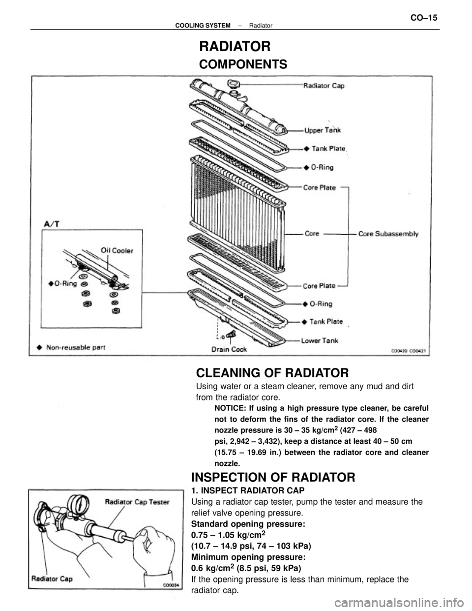
INSPECTION OF RADIATOR
1. INSPECT RADIATOR CAP
Using a radiator cap tester, pump the tester and measure the
relief valve opening pressure.
Standard opening pressure:
0.75 ± 1.05 kg/cm
2
(10.7 ± 14.9 psi, 74 ± 103 kPa)
Minimum opening pressure:
0.6 kg/cm
2 (8.5 psi, 59 kPa)
If the opening pressure is less than minimum, replace the
radiator cap.
CLEANING OF RADIATOR
Using water or a steam cleaner, remove any mud and dirt
from the radiator core.
NOTICE: If using a high pressure type cleaner, be careful
not to deform the fins of the radiator core. If the cleaner
nozzle pressure is 30 ± 35 kg/cm
2 (427 ± 498
psi, 2,942 ± 3,432), keep a distance at least 40 ± 50 cm
(15.75 ± 19.69 in.) between the radiator core and cleaner
nozzle.
RADIATOR
COMPONENTS
± COOLING SYSTEMRadiatorCO±15
Page 1003 of 2389
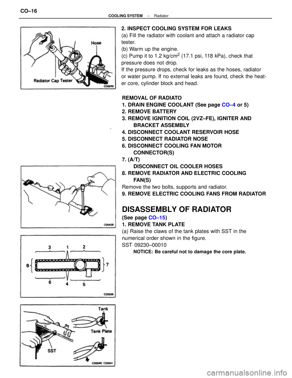
REMOVAL OF RADIATO
1. DRAIN ENGINE COOLANT (See page CO±4 or 5)
2. REMOVE BATTERY
3. REMOVE IGNITION COIL (2VZ±FE), IGNITER AND
BRACKET ASSEMBLY
4. DISCONNECT COOLANT RESERVOIR HOSE
5. DISCONNECT RADIATOR NOSE
6. DISCONNECT COOLING FAN MOTOR
CONNECTOR(S)
7. (A/T)
DISCONNECT OIL COOLER HOSES
8. REMOVE RADIATOR AND ELECTRIC COOLING
FAN(S)
Remove the two bolts, supports and radiator.
9. REMOVE ELECTRIC COOLING FANS FROM RADIATOR
DISASSEMBLY OF RADIATOR
(See page CO±15)
1. REMOVE TANK PLATE
(a) Raise the claws of the tank plates with SST in the
numerical order shown in the figure.
SST 09230±00010
NOTICE: Be careful not to damage the core plate.
2. INSPECT COOLING SYSTEM FOR LEAKS
(a) Fill the radiator with coolant and attach a radiator cap
tester.
(b) Warm up the engine.
(c) Pump it to 1.2 kg/cm
2 (17.1 psi, 118 kPa), check that
pressure does not drop.
If the pressure drops, check for leaks as the hoses, radiator
or water pump. If no external leaks are found, check the heat-
er core, cylinder block and head.
± COOLING SYSTEMRadiatorCO±16
Page 1004 of 2389
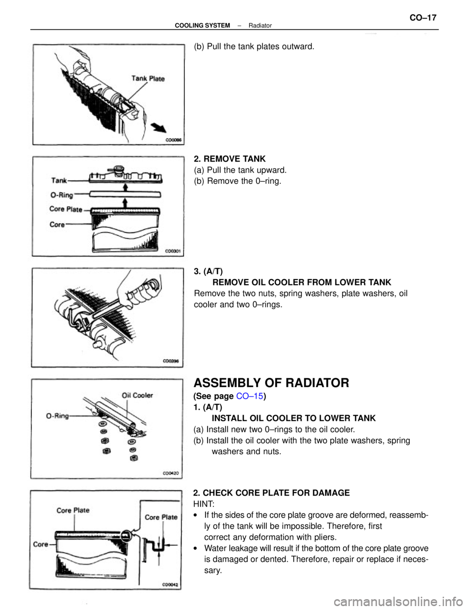
2. CHECK CORE PLATE FOR DAMAGE
HINT:
wIf the sides of the core plate groove are deformed, reassemb-
ly of the tank will be impossible. Therefore, first
correct any deformation with pliers.
wWater leakage will result if the bottom of the core plate groove
is damaged or dented. Therefore, repair or replace if neces-
sary.
ASSEMBLY OF RADIATOR
(See page CO±15)
1. (A/T)
INSTALL OIL COOLER TO LOWER TANK
(a) Install new two 0±rings to the oil cooler.
(b) Install the oil cooler with the two plate washers, spring
washers and nuts. 3. (A/T)
REMOVE OIL COOLER FROM LOWER TANK
Remove the two nuts, spring washers, plate washers, oil
cooler and two 0±rings. 2. REMOVE TANK
(a) Pull the tank upward.
(b) Remove the 0±ring. (b) Pull the tank plates outward.
± COOLING SYSTEMRadiatorCO±17