Page 2207 of 2389
Stabilizer Bar
(See page RA±50)
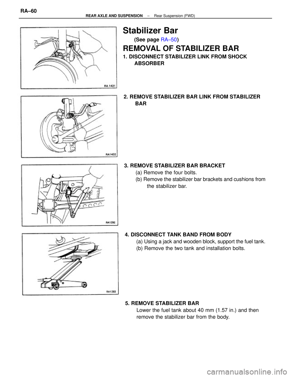
REMOVAL OF STABILIZER BAR
1. DISCONNECT STABILIZER LINK FROM SHOCK
ABSORBER
3. REMOVE STABILIZER BAR BRACKET
(a) Remove the four bolts.
(b) Remove the stabilizer bar brackets and cushions from
the stabilizer bar.
4. DISCONNECT TANK BAND FROM BODY
(a) Using a jack and wooden block, support the fuel tank.
(b) Remove the two tank and installation bolts.
5. REMOVE STABILIZER BAR
Lower the fuel tank about 40 mm (1.57 in.) and then
remove the stabilizer bar from the body. 2. REMOVE STABILIZER BAR LINK FROM STABILIZER
BAR
± REAR AXLE AND SUSPENSIONRear Suspension (FWD)RA±60
Page 2208 of 2389
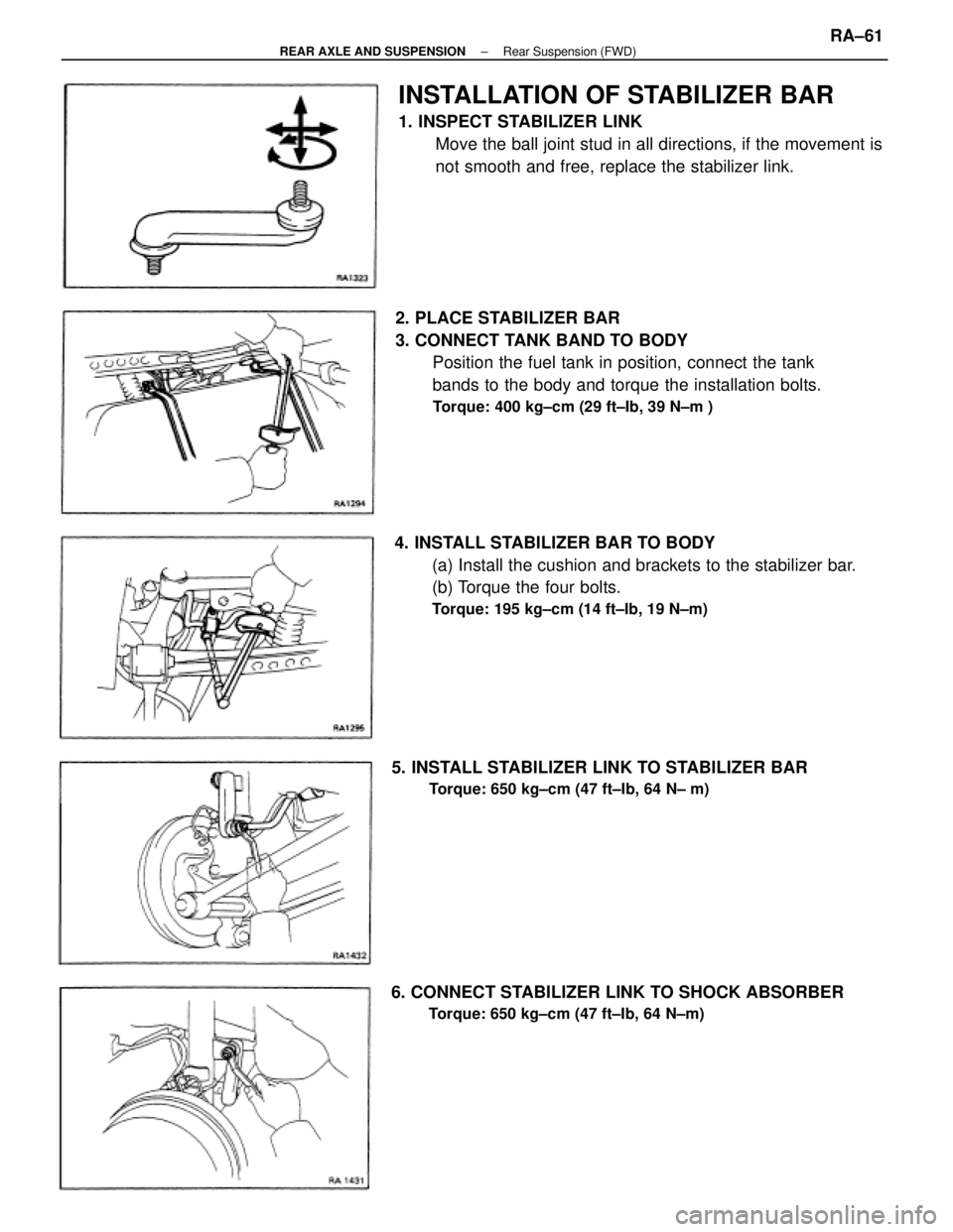
2. PLACE STABILIZER BAR
3. CONNECT TANK BAND TO BODY
Position the fuel tank in position, connect the tank
bands to the body and torque the installation bolts.
Torque: 400 kg±cm (29 ft±Ib, 39 N±m )
INSTALLATION OF STABILIZER BAR
1. INSPECT STABILIZER LINK
Move the ball joint stud in all directions, if the movement is
not smooth and free, replace the stabilizer link.
4. INSTALL STABILIZER BAR TO BODY
(a) Install the cushion and brackets to the stabilizer bar.
(b) Torque the four bolts.
Torque: 195 kg±cm (14 ft±Ib, 19 N±m)
6. CONNECT STABILIZER LINK TO SHOCK ABSORBER
Torque: 650 kg±cm (47 ft±Ib, 64 N±m)
5. INSTALL STABILIZER LINK TO STABILIZER BAR
Torque: 650 kg±cm (47 ft±Ib, 64 N± m)
± REAR AXLE AND SUSPENSIONRear Suspension (FWD)RA±61
Page 2209 of 2389
REAR SUSPENSION (4WD)
HINT: Refer to RA±50 except following points about
4WD.
COMPONENTS
± REAR AXLE AND SUSPENSIONRear Suspension (4WD)RA±62
Page 2210 of 2389
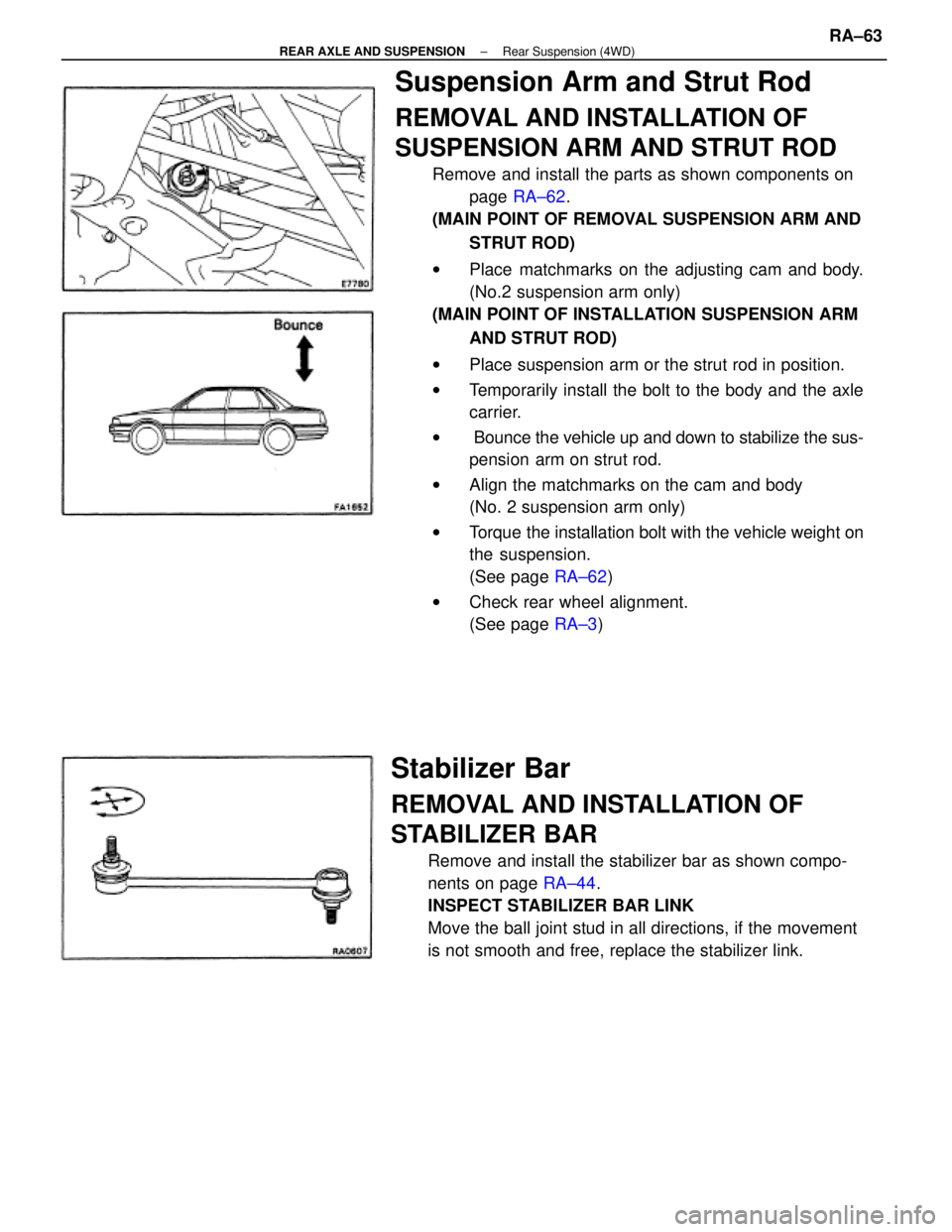
Suspension Arm and Strut Rod
REMOVAL AND INSTALLATION OF
SUSPENSION ARM AND STRUT ROD
Remove and install the parts as shown components on
page RA±62.
(MAIN POINT OF REMOVAL SUSPENSION ARM AND
STRUT ROD)
wPlace matchmarks on the adjusting cam and body.
(No.2 suspension arm only)
(MAIN POINT OF INSTALLATION SUSPENSION ARM
AND STRUT ROD)
wPlace suspension arm or the strut rod in position.
wTemporarily install the bolt to the body and the axle
carrier.
w Bounce the vehicle up and down to stabilize the sus-
pension arm on strut rod.
wAlign the matchmarks on the cam and body
(No. 2 suspension arm only)
wTorque the installation bolt with the vehicle weight on
the suspension.
(See page RA±62)
wCheck rear wheel alignment.
(See page RA±3)
Stabilizer Bar
REMOVAL AND INSTALLATION OF
STABILIZER BAR
Remove and install the stabilizer bar as shown compo-
nents on page RA±44.
INSPECT STABILIZER BAR LINK
Move the ball joint stud in all directions, if the movement
is not smooth and free, replace the stabilizer link.
± REAR AXLE AND SUSPENSIONRear Suspension (4WD)RA±63
Page 2211 of 2389
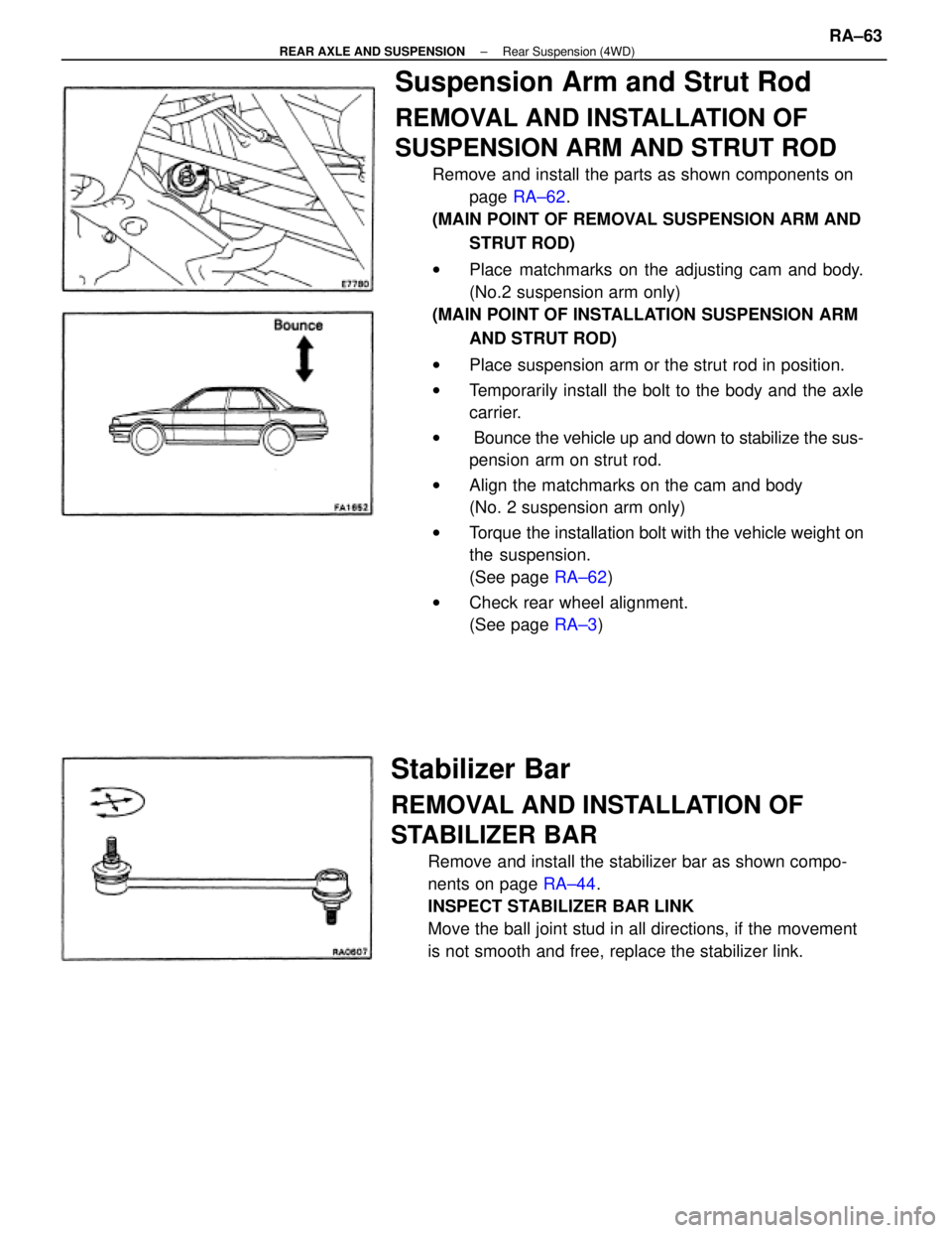
Suspension Arm and Strut Rod
REMOVAL AND INSTALLATION OF
SUSPENSION ARM AND STRUT ROD
Remove and install the parts as shown components on
page RA±62.
(MAIN POINT OF REMOVAL SUSPENSION ARM AND
STRUT ROD)
wPlace matchmarks on the adjusting cam and body.
(No.2 suspension arm only)
(MAIN POINT OF INSTALLATION SUSPENSION ARM
AND STRUT ROD)
wPlace suspension arm or the strut rod in position.
wTemporarily install the bolt to the body and the axle
carrier.
w Bounce the vehicle up and down to stabilize the sus-
pension arm on strut rod.
wAlign the matchmarks on the cam and body
(No. 2 suspension arm only)
wTorque the installation bolt with the vehicle weight on
the suspension.
(See page RA±62)
wCheck rear wheel alignment.
(See page RA±3)
Stabilizer Bar
REMOVAL AND INSTALLATION OF
STABILIZER BAR
Remove and install the stabilizer bar as shown compo-
nents on page RA±44.
INSPECT STABILIZER BAR LINK
Move the ball joint stud in all directions, if the movement
is not smooth and free, replace the stabilizer link.
± REAR AXLE AND SUSPENSIONRear Suspension (4WD)RA±63
Page 2213 of 2389
Front and rear brake
Pad thickness
Disc thickness
Disc runout
Parking brake
Lining thickness
Drum inside diameter
Front axle and suspension
Ball joint vertical play
Steering wheel freeplay
Torque specifications
Front seat mount bolts
Strut/stabilizer bar bracket x Body
Engine mounting center member x Body
Front suspension lower crossmember x Body
Rear suspension lower crossmember x Body
MAINTENANCE
Engine
Engine oil capacity (Drain and refill with oil fitter change)
Gap
Firing order
Valve clearance Coolant capacity 1w/ Heater) Drive belt tension
Alternator
Spark plug
Type
Chassis
PS pump
± SERVICE SPECIFICATIONSMaintenanceA±2
Page 2217 of 2389
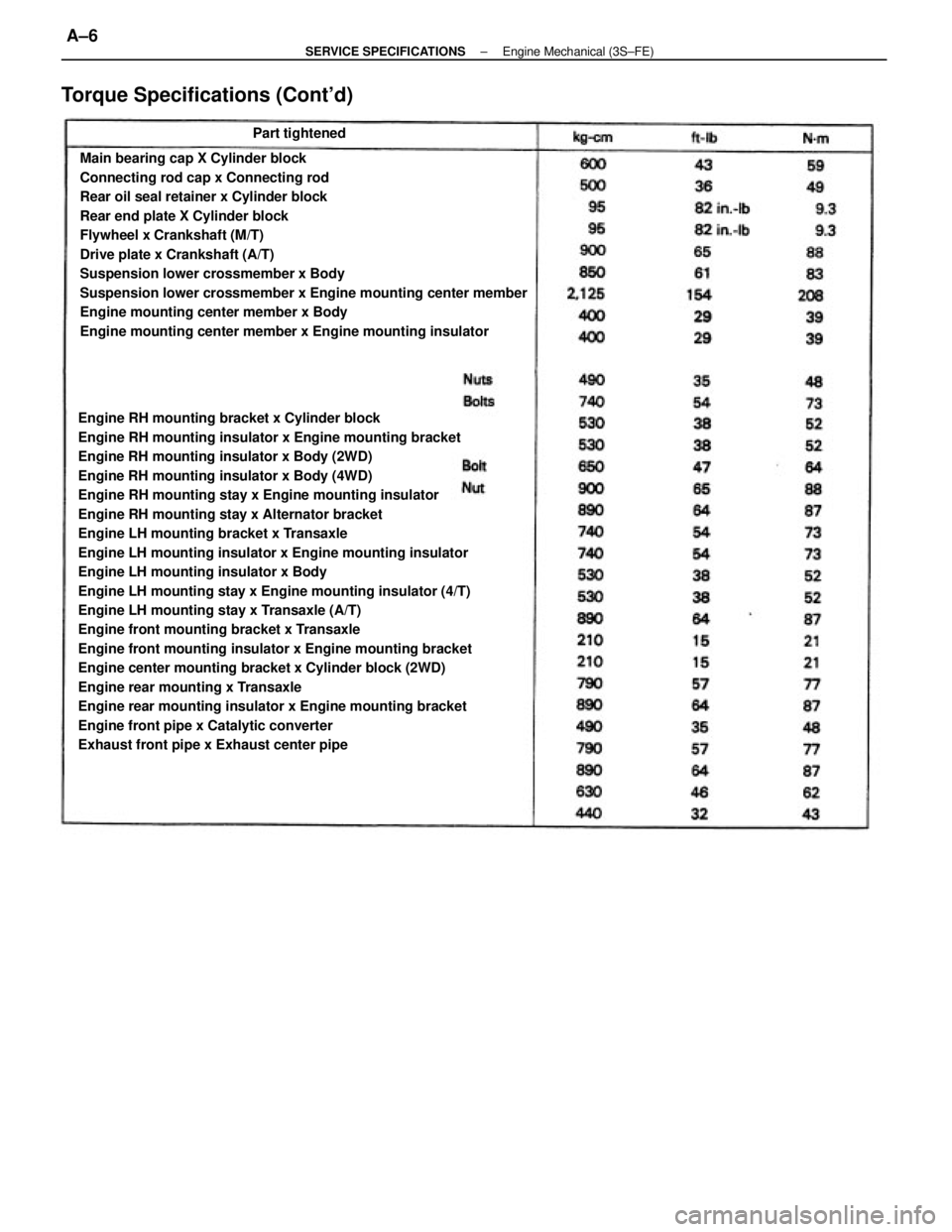
Engine RH mounting bracket x Cylinder block
Engine RH mounting insulator x Engine mounting bracket
Engine RH mounting insulator x Body (2WD)
Engine RH mounting insulator x Body (4WD)
Engine RH mounting stay x Engine mounting insulator
Engine RH mounting stay x Alternator bracket
Engine LH mounting bracket x Transaxle
Engine LH mounting insulator x Engine mounting insulator
Engine LH mounting insulator x Body
Engine LH mounting stay x Engine mounting insulator (4/T)
Engine LH mounting stay x Transaxle (A/T)
Engine front mounting bracket x Transaxle
Engine front mounting insulator x Engine mounting bracket
Engine center mounting bracket x Cylinder block (2WD)
Engine rear mounting x Transaxle
Engine rear mounting insulator x Engine mounting bracket
Engine front pipe x Catalytic converter
Exhaust front pipe x Exhaust center pipeMain bearing cap X Cylinder block
Connecting rod cap x Connecting rod
Rear oil seal retainer x Cylinder block
Rear end plate X Cylinder block
Flywheel x Crankshaft (M/T)
Drive plate x Crankshaft (A/T)
Suspension lower crossmember x Body
Suspension lower crossmember x Engine mounting center member
Engine mounting center member x Body
Engine mounting center member x Engine mounting insulator
Torque Specifications (Cont'd)
Part tightened
± SERVICE SPECIFICATIONSEngine Mechanical (3S±FE)A±6
Page 2221 of 2389
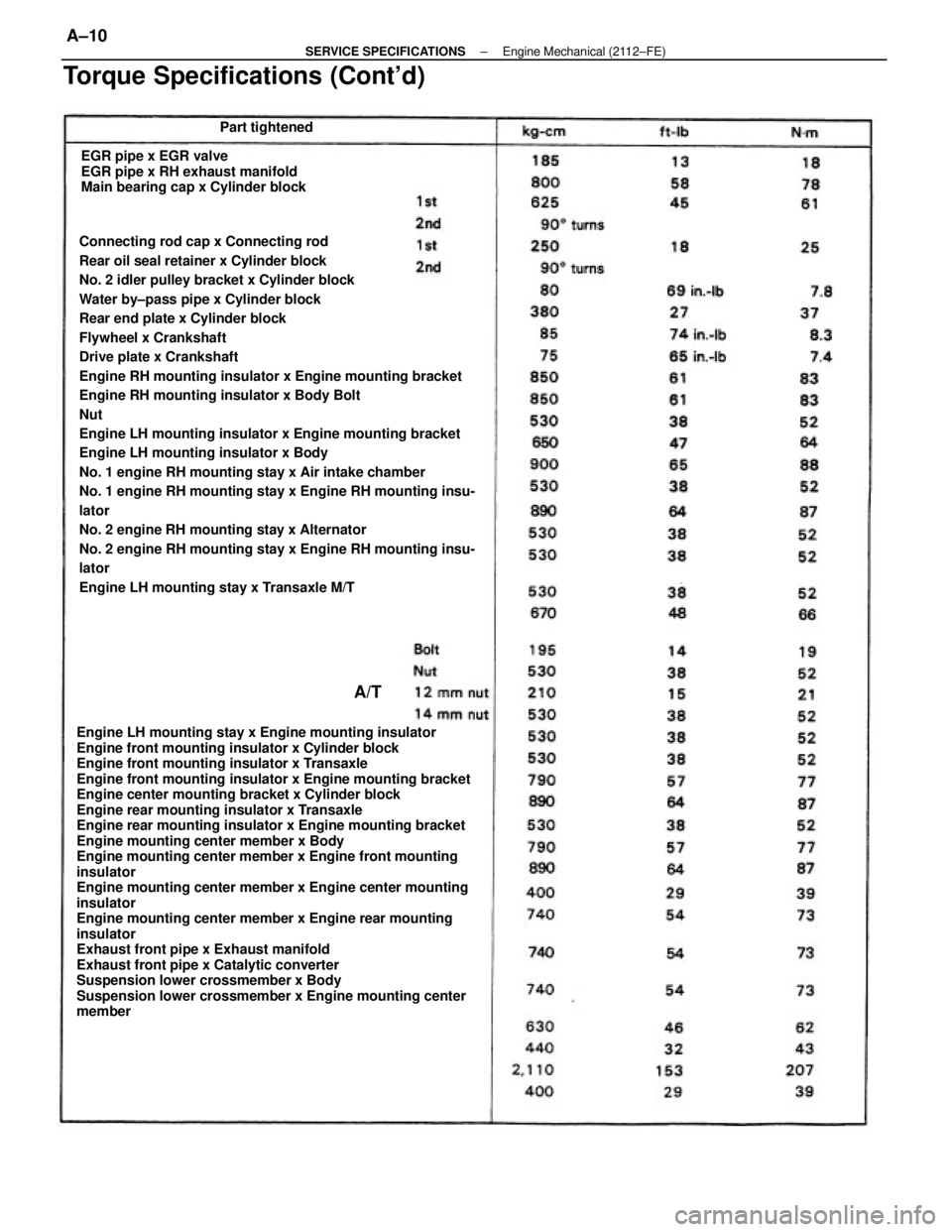
Connecting rod cap x Connecting rod
Rear oil seal retainer x Cylinder block
No. 2 idler pulley bracket x Cylinder block
Water by±pass pipe x Cylinder block
Rear end plate x Cylinder block
Flywheel x Crankshaft
Drive plate x Crankshaft
Engine RH mounting insulator x Engine mounting bracket
Engine RH mounting insulator x Body Bolt
Nut
Engine LH mounting insulator x Engine mounting bracket
Engine LH mounting insulator x Body
No. 1 engine RH mounting stay x Air intake chamber
No. 1 engine RH mounting stay x Engine RH mounting insu-
lator
No. 2 engine RH mounting stay x Alternator
No. 2 engine RH mounting stay x Engine RH mounting insu-
lator
Engine LH mounting stay x Transaxle M/T
Engine LH mounting stay x Engine mounting insulator
Engine front mounting insulator x Cylinder block
Engine front mounting insulator x Transaxle
Engine front mounting insulator x Engine mounting bracket
Engine center mounting bracket x Cylinder block
Engine rear mounting insulator x Transaxle
Engine rear mounting insulator x Engine mounting bracket
Engine mounting center member x Body
Engine mounting center member x Engine front mounting
insulator
Engine mounting center member x Engine center mounting
insulator
Engine mounting center member x Engine rear mounting
insulator
Exhaust front pipe x Exhaust manifold
Exhaust front pipe x Catalytic converter
Suspension lower crossmember x Body
Suspension lower crossmember x Engine mounting center
memberEGR pipe x EGR valve
EGR pipe x RH exhaust manifold
Main bearing cap x Cylinder block
Torque Specifications (Cont'd)
Part tightened
A/T
± SERVICE SPECIFICATIONSEngine Mechanical (2112±FE)A±10