Page 1914 of 2389

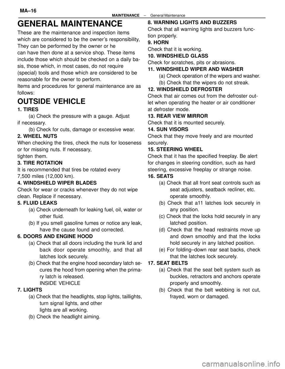
GENERAL MAINTENANCE
These are the maintenance and inspection items
which are considered to be the owner's responsibility,
They can be performed by the owner or he
can have then done at a service shop. These items
include those which should be checked on a daily ba-
sis, those which, in most cases, do not require
(special) tools and those which are considered to be
reasonable for the owner to perform.
Items and procedures for general maintenance are as
follows:
OUTSIDE VEHICLE
1. TIRES
(a) Check the pressure with a gauge. Adjust
if necessary.
(b) Check for cuts, damage or excessive wear.
2. WHEEL NUTS
When checking the tires, check the nuts for looseness
or for missing nuts. If necessary,
tighten them.
3. TIRE ROTATION
It is recommended that tires be rotated every
7,500 miles (12,000 km).
4. WINDSHIELD WIPER BLADES
Check for wear or cracks whenever they do not wipe
clean. Replace if necessary.
5. FLUID LEAKS
(a) Check underneath for leaking fuel, oil, water or
other fluid.
(b) If you smell gasoline fumes or notice any leak,
have the cause found and corrected.
6. DOORS AND ENGINE HOOD
(a) Check that all doors including the trunk lid and
back door operate smoothly, and that all
latches lock securely.
(b) Check that the engine hood secondary latch se-
cures the hood from opening when the prima-
ry latch is released.
INSIDE VEHICLE
7. LIGHTS
(a) Check that the headlights, stop lights, taillights,
turn signal lights, and other
lights are all working.
(b) Check the headlight aiming.8. WARNING LIGHTS AND BUZZERS
Check that all warning lights and buzzers func-
tion properly.
9. HORN
Check that it is working.
10. WINDSHIELD GLASS
Check for scratches, pits or abrasions.
11. WINDSHIELD WIPER AND WASHER
(a) Check operation of the wipers and washer.
(b) Check that the wipers do not streak.
12. WINDSHIELD DEFROSTER
Check that air comes out from the defroster out-
let when operating the heater or air conditioner
at defroster mode.
13. REAR VIEW MIRROR
Check that it is mounted securely.
14. SUN VISORS
Check that they move freely and are mounted
securely.
15. STEERING WHEEL
Check that it has the specified freeplay. Be alert
for changes in steering condition, such as hard
steering, excessive freeplay or strange noise.
16. SEATS
(a) Check that all front seat controls such as
seat adjusters, seatback recliner, etc.
operate smoothly.
(b) Check that a11 latches lock securely in
any position.
(c) Check that the locks hold securely in any
latched position.
(d) Check that the head restraints move up
and down smoothly and that the locks
hold securely in any latched position.
(e) For folding±down rear seat backs, check
that the latches lock securely.
17. SEAT BELTS
(a) Check that the seat belt system such as
buckles, retractors and anchors operate
properly and smoothly.
(b) Check that the belt webbing is not cut,
frayed, worn or damaged.
± MAINTENANCEGeneral MaintenanceMA±16
Page 1915 of 2389

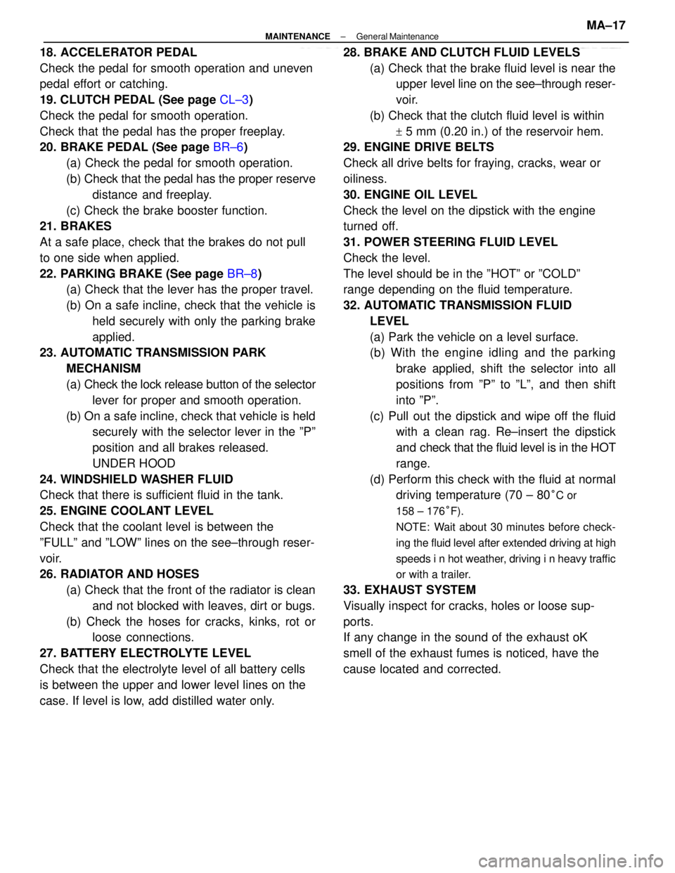
18. ACCELERATOR PEDAL
Check the pedal for smooth operation and uneven
pedal effort or catching.
19. CLUTCH PEDAL (See page CL±3)
Check the pedal for smooth operation.
Check that the pedal has the proper freeplay.
20. BRAKE PEDAL (See page BR±6)
(a) Check the pedal for smooth operation.
(b) Check that the pedal has the proper reserve
distance and freeplay.
(c) Check the brake booster function.
21. BRAKES
At a safe place, check that the brakes do not pull
to one side when applied.
22. PARKING BRAKE (See page BR±8)
(a) Check that the lever has the proper travel.
(b) On a safe incline, check that the vehicle is
held securely with only the parking brake
applied.
23. AUTOMATIC TRANSMISSION PARK
MECHANISM
(a) Check the lock release button of the selector
lever for proper and smooth operation.
(b) On a safe incline, check that vehicle is held
securely with the selector lever in the ºPº
position and all brakes released.
UNDER HOOD
24. WINDSHIELD WASHER FLUID
Check that there is sufficient fluid in the tank.
25. ENGINE COOLANT LEVEL
Check that the coolant level is between the
ºFULLº and ºLOWº lines on the see±through reser-
voir.
26. RADIATOR AND HOSES
(a) Check that the front of the radiator is clean
and not blocked with leaves, dirt or bugs.
(b) Check the hoses for cracks, kinks, rot or
loose connections.
27. BATTERY ELECTROLYTE LEVEL
Check that the electrolyte level of all battery cells
is between the upper and lower level lines on the
case. If level is low, add distilled water only.28. BRAKE AND CLUTCH FLUID LEVELS
(a) Check that the brake fluid level is near the
upper level line on the see±through reser-
voir.
(b) Check that the clutch fluid level is within
+ 5 mm (0.20 in.) of the reservoir hem.
29. ENGINE DRIVE BELTS
Check all drive belts for fraying, cracks, wear or
oiliness.
30. ENGINE OIL LEVEL
Check the level on the dipstick with the engine
turned off.
31. POWER STEERING FLUID LEVEL
Check the level.
The level should be in the ºHOTº or ºCOLDº
range depending on the fluid temperature.
32. AUTOMATIC TRANSMISSION FLUID
LEVEL
(a) Park the vehicle on a level surface.
(b) With the engine idling and the parking
brake applied, shift the selector into all
positions from ºPº to ºLº, and then shift
into ºPº.
(c) Pull out the dipstick and wipe off the fluid
with a clean rag. Re±insert the dipstick
and check that the fluid level is in the HOT
range.
(d) Perform this check with the fluid at normal
driving temperature (70 ± 80
°C or
158 ± 176°F).
NOTE: Wait about 30 minutes before check-
ing the fluid level after extended driving at high
speeds i n hot weather, driving i n heavy traffic
or with a trailer.
33. EXHAUST SYSTEM
Visually inspect for cracks, holes or loose sup-
ports.
If any change in the sound of the exhaust oK
smell of the exhaust fumes is noticed, have the
cause located and corrected.
± MAINTENANCEGeneral MaintenanceMA±17
Page 1916 of 2389

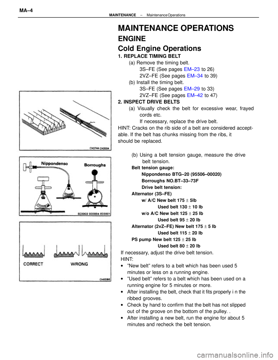
(b) Using a belt tension gauge, measure the drive
belt tension.
Belt tension gauge:
Nippondenso BTG±20 (95506±00020)
Borroughs NO.BT±33±73F
Drive belt tension:
Alternator (3S±FE)
w/ A/C New belt 175 + 5lb
Used belt 130 + 10 lb
w/o A/C New belt 125 + 25 Ib
Used belt 95 + 20 Ib
Alternator (2vZ±FE) New belt 175 + 5 Ib
Used belt 115 + 20 Ib
PS pump New belt 125 + 25 Ib
Used belt 80 + 20 lb
If necessary, adjust the drive belt tension.
HINT:
wºNew beltº refers to a belt which has been used 5
minutes or less on a running engine.
wºUsed beltº refers to a belt which has been used on a
running engine for 5 minutes or more.
wAfter installing the belt, check that it fits properly i n the
ribbed grooves.
wCheck by hand to confirm that the belt has not slipped
out of the groove on the bottom of the pulley. .
wAfter installing a new belt, run the engine for about 5
minutes and recheck the belt tension.
MAINTENANCE OPERATIONS
ENGINE
Cold Engine Operations
1. REPLACE TIMING BELT
(a) Remove the timing belt.
3S±FE (See pages EM±23 to 26)
2VZ±FE (See pages EM±34 to 39)
(b) Install the timing belt.
3S±FE (See pages EM±29 to 33)
2VZ±FE (See pages EM±42 to 47)
2. INSPECT DRIVE BELTS
(a) Visually check the belt for excessive wear, frayed
cords etc.
If necessary, replace the drive belt.
HINT: Cracks on the rib side of a belt are considered accept-
able. If the belt has chunks missing from the ribs, it
should be replaced.
± MAINTENANCEMaintenance OperationsMA±4
Page 2213 of 2389
Front and rear brake
Pad thickness
Disc thickness
Disc runout
Parking brake
Lining thickness
Drum inside diameter
Front axle and suspension
Ball joint vertical play
Steering wheel freeplay
Torque specifications
Front seat mount bolts
Strut/stabilizer bar bracket x Body
Engine mounting center member x Body
Front suspension lower crossmember x Body
Rear suspension lower crossmember x Body
MAINTENANCE
Engine
Engine oil capacity (Drain and refill with oil fitter change)
Gap
Firing order
Valve clearance Coolant capacity 1w/ Heater) Drive belt tension
Alternator
Spark plug
Type
Chassis
PS pump
± SERVICE SPECIFICATIONSMaintenanceA±2
Page 2219 of 2389
Specifications (Cont'd)
Connecting rod Timing belt
tensioner
Piston and
piston ring Camshaft
(cont'd)
Cylinder block
Crankshaft
± SERVICE SPECIFICATIONSEngine Mechanical (2VZ±±FE)A±8
Page 2220 of 2389

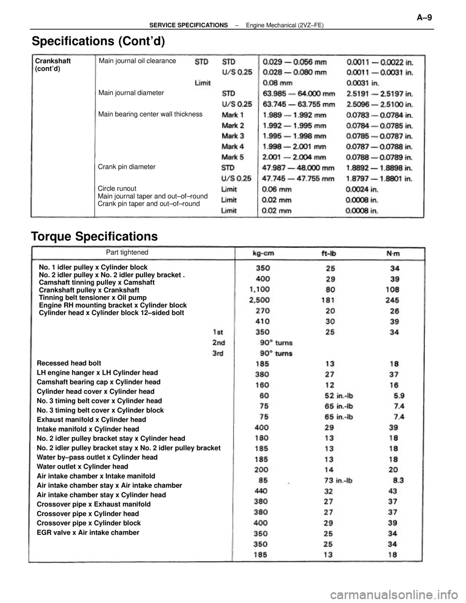
Recessed head bolt
LH engine hanger x LH Cylinder head
Camshaft bearing cap x Cylinder head
Cylinder head cover x Cylinder head
No. 3 timing belt cover x Cylinder head
No. 3 timing belt cover x Cylinder block
Exhaust manifold x Cylinder head
Intake manifold x Cylinder head
No. 2 idler pulley bracket stay x Cylinder head
No. 2 idler pulley bracket stay x No. 2 idler pulley bracket
Water by±pass outlet x Cylinder head
Water outlet x Cylinder head
Air intake chamber x Intake manifold
Air intake chamber stay x Air intake chamber
Air intake chamber stay x Cylinder head
Crossover pipe x Exhaust manifold
Crossover pipe x Cylinder head
Crossover pipe x Cylinder block
EGR valve x Air intake chamberNo. 1 idler pulley x Cylinder block
No. 2 idler pulley x No. 2 idler pulley bracket .
Camshaft tinning pulley x Camshaft
Crankshaft pulley x Crankshaft
Tinning belt tensioner x Oil pump
Engine RH mounting bracket x Cylinder block
Cylinder head x Cylinder block 12±sided boltCircle runout
Main journal taper and out±of±round
Crank pin taper and out±of±round
Torque SpecificationsSpecifications (Cont'd)
Main bearing center wall thicknessMain journal oil clearance
Main journal diameter
Crank pin diameter Crankshaft
(cont'd)
Part tightened
± SERVICE SPECIFICATIONSEngine Mechanical (2VZ±FE)A±9
Page 2225 of 2389
Engine coolant x Drain plug
Water pump x Water pump cover
Water pump x Cylinder head
Water by±pass pipe X Water pump
Water inlet housing x Water pump
Oil cooler x Radiator tower tank
Cylinder block x Drain plug
Water pump x Cylinder block
Water inlet x Water pump
Water inlet pipe x Alternator belt adjusting bar
LUBRICATION SYSTEM (3S±FE)
SpecificationsTorque Specifi
cations (3S±FE)
COOLING SYSTEM
Specifications
Torque Specifications (2VZ±FE)
Valve opening temperature
Valve lift at 95°C (203°F) Relief valve opening pressure
Engine coolant capacityEngine coolant capacity
at Idling
at 3,040 rpm
STD
Limit
STD
Limit Body clearance .See page A±20 STD
Limit
Part tightened
Part tightenedSee page A±2
Tip clearance3S±FE
2VZ±FE
Oil pressureThermostat
Oil pumpRadiator
± SERVICE SPECIFICATIONSCooling SystemA±17
Page 2229 of 2389
Engine coolant x Drain plug
Water pump x Water pump cover
Water pump x Cylinder head
Water by±pass pipe X Water pump
Water inlet housing x Water pump
Oil cooler x Radiator tower tank
Cylinder block x Drain plug
Water pump x Cylinder block
Water inlet x Water pump
Water inlet pipe x Alternator belt adjusting bar
LUBRICATION SYSTEM (3S±FE)
SpecificationsTorque Specifi
cations (3S±FE)
COOLING SYSTEM
Specifications
Torque Specifications (2VZ±FE)
Valve opening temperature
Valve lift at 95°C (203°F) Relief valve opening pressure
Engine coolant capacityEngine coolant capacity
at Idling
at 3,040 rpm
STD
Limit
STD
Limit Body clearance .See page A±20 STD
Limit
Part tightened
Part tightenedSee page A±2
Tip clearance3S±FE
2VZ±FE
Oil pressureThermostat
Oil pumpRadiator
± SERVICE SPECIFICATIONSLubrication System (3S±FE)A±17