1985 FORD GRANADA air filter
[x] Cancel search: air filterPage 96 of 255
Fuel and exhaust systems 4•3
4
Weber 2V TLD carburettorPrimarySecondary
Venturi diameter . . . . . . . . . . . . . . . . . . . . . . . . . . . . . . . . . . . . . . . . . . .23.0 mm25.0 mm
Main jet:
Manual gearbox . . . . . . . . . . . . . . . . . . . . . . . . . . . . . . . . . . . . . . . . .115157
Automatic transmission . . . . . . . . . . . . . . . . . . . . . . . . . . . . . . . . . . .112157
Air correction jet:
Manual gearbox . . . . . . . . . . . . . . . . . . . . . . . . . . . . . . . . . . . . . . . . .175145
Automatic transmission . . . . . . . . . . . . . . . . . . . . . . . . . . . . . . . . . . .210145
Emulsion tube:
Manual gearbox . . . . . . . . . . . . . . . . . . . . . . . . . . . . . . . . . . . . . . . . .F114F3
Automatic transmission . . . . . . . . . . . . . . . . . . . . . . . . . . . . . . . . . . .210145
Fast idle speed . . . . . . . . . . . . . . . . . . . . . . . . . . . . . . . . . . . . . . . . . . . .1800 ±50 rpm
Float level (with gasket) . . . . . . . . . . . . . . . . . . . . . . . . . . . . . . . . . . . . .29.0 ±0.5 mm
Automatic choke vacuum pull-down . . . . . . . . . . . . . . . . . . . . . . . . . . .5.0 ±0.5 mm
Throttle kicker speed (see text):
Manual gearbox . . . . . . . . . . . . . . . . . . . . . . . . . . . . . . . . . . . . . . . . .2000 ±50 rpm
Automatic transmission . . . . . . . . . . . . . . . . . . . . . . . . . . . . . . . . . . .2200 ±50 rpm
Fuel-injection system
Make . . . . . . . . . . . . . . . . . . . . . . . . . . . . . . . . . . . . . . . . . . . . . . . . . . . .Bosch
Fuel pump type . . . . . . . . . . . . . . . . . . . . . . . . . . . . . . . . . . . . . . . . . . . .Roller cell, electric
Fuel pump output pressure . . . . . . . . . . . . . . . . . . . . . . . . . . . . . . . . . .Greater than 5 bar at 12 volts, no flow
System control pressure . . . . . . . . . . . . . . . . . . . . . . . . . . . . . . . . . . . . .2.5 bar
Torque wrench settingsNmlbf ft
Inlet manifold:
SOHC . . . . . . . . . . . . . . . . . . . . . . . . . . . . . . . . . . . . . . . . . . . . . . . . .17 to 2113 to 16
DOHC . . . . . . . . . . . . . . . . . . . . . . . . . . . . . . . . . . . . . . . . . . . . . . . . .20 to 2415 to 18
V6:
Stage 1 . . . . . . . . . . . . . . . . . . . . . . . . . . . . . . . . . . . . . . . . . . . . . .4 to 83 to 6
Stage 2 . . . . . . . . . . . . . . . . . . . . . . . . . . . . . . . . . . . . . . . . . . . . . .8 to 156 to 11
Stage 3 . . . . . . . . . . . . . . . . . . . . . . . . . . . . . . . . . . . . . . . . . . . . . .15 to 2111 to 16
Stage 4 . . . . . . . . . . . . . . . . . . . . . . . . . . . . . . . . . . . . . . . . . . . . . .21 to 2516 to 18
Stage 5 (after warm-up) . . . . . . . . . . . . . . . . . . . . . . . . . . . . . . . . .21 to 2516 to 18
Exhaust manifold:
OHC . . . . . . . . . . . . . . . . . . . . . . . . . . . . . . . . . . . . . . . . . . . . . . . . . .21 to 2516 to 18
V6 . . . . . . . . . . . . . . . . . . . . . . . . . . . . . . . . . . . . . . . . . . . . . . . . . . . .25 to 3018 to 22
Plenum chamber to inlet manifold:
2.8 litre . . . . . . . . . . . . . . . . . . . . . . . . . . . . . . . . . . . . . . . . . . . . . . . .7 to 105 to 7
2.4 & 2.9 litre . . . . . . . . . . . . . . . . . . . . . . . . . . . . . . . . . . . . . . . . . . . .20 to 2515 to 18
Carburettor bolts (DOHC) . . . . . . . . . . . . . . . . . . . . . . . . . . . . . . . . . . . .8 to 106 to 7
Fuel pump bolts (mechanical pump) . . . . . . . . . . . . . . . . . . . . . . . . . . .14 to 1810 to 13
Fuel pipe to fuel-injection pressure regulator:
SOHC . . . . . . . . . . . . . . . . . . . . . . . . . . . . . . . . . . . . . . . . . . . . . . . . .15 to 2011 to 15
2.8 litre . . . . . . . . . . . . . . . . . . . . . . . . . . . . . . . . . . . . . . . . . . . . . . . .10 to 127 to 9
Pressure regulator base nut/bolt:
SOHC . . . . . . . . . . . . . . . . . . . . . . . . . . . . . . . . . . . . . . . . . . . . . . . . .20 to 2515 to 18
DOHC . . . . . . . . . . . . . . . . . . . . . . . . . . . . . . . . . . . . . . . . . . . . . . . . .9 to 127 to 9
V6:
2.8 litre . . . . . . . . . . . . . . . . . . . . . . . . . . . . . . . . . . . . . . . . . . . . . .15 to 2011 to 15
2.4 & 2.9 litre . . . . . . . . . . . . . . . . . . . . . . . . . . . . . . . . . . . . . . . . . .9 to 117 to 8
Fuel rail bolts:
SOHC . . . . . . . . . . . . . . . . . . . . . . . . . . . . . . . . . . . . . . . . . . . . . . . . .9 to 117 to 8
DOHC . . . . . . . . . . . . . . . . . . . . . . . . . . . . . . . . . . . . . . . . . . . . . . . . .21 to 2615 to 19
Exhaust downpipe flange nuts . . . . . . . . . . . . . . . . . . . . . . . . . . . . . . . .35 to 4026 to 30
Exhaust clamps and U-bolts . . . . . . . . . . . . . . . . . . . . . . . . . . . . . . . . .38 to 4528 to 33
Exhaust gas oxygen sensor . . . . . . . . . . . . . . . . . . . . . . . . . . . . . . . . . .50 to 7037 to 52
Throttle body bolts . . . . . . . . . . . . . . . . . . . . . . . . . . . . . . . . . . . . . . . . .9 to 117 to 8
Idle speed control valve bolts . . . . . . . . . . . . . . . . . . . . . . . . . . . . . . . . .9 to 117 to 8
Fuel filter unions . . . . . . . . . . . . . . . . . . . . . . . . . . . . . . . . . . . . . . . . . . .14 to 2010 to 15
Fuel rail temperature sensor (DOHC) . . . . . . . . . . . . . . . . . . . . . . . . . . .8 to 116 to 8
Fuel rail temperature switch (2.4 & 2.9 litre) . . . . . . . . . . . . . . . . . . . . . .20 to 2515 to 18
HEGO sensor . . . . . . . . . . . . . . . . . . . . . . . . . . . . . . . . . . . . . . . . . . . . .50 to 7037 to 52
All models are fitted with a rear-mounted fuel
tank. Fuel is conveyed from the tank by a
mechanical or electrical fuel pump, according tomodel and equipment, to the carburettor or fuel-
injection system. The delivery capacity of the
fuel pump exceeds the maximum demands of
the system, so excess fuel is constantly returned
to the tank. This helps to avoid the problems of
vapour locks in the fuel lines.
Carburettor models have a twin venturidowndraught carburettor of Pierburg
manufacture on 1.8 litre models and Weber on
2.0 litre models. Both makes of carburettor
have an automatic choke.
Fuel-injection, when fitted, is of the Bosch
L-Jetronic type. This system is under the
control of the EEC IV module.
1General information and
precautions
procarmanuals.com
Page 97 of 255
The exhaust system fitted in production is
made of aluminised steel, with stainless steel
used in the endplates and baffles of the rear
silencer. Individual sections of the system are
easily renewed in service.
Emission control for the UK market is
achieved largely by the inherent efficiency of
the fuel, ignition and engine management
systems. A welcome spin-off from such
efficiency is remarkably good fuel economy for
a vehicle of such size and weight.
Precautions
Fuel
Many of the procedures in this Chapter
require the removal of fuel lines and
connections which may result in some fuel
spillage. Residual pressure in fuel-injection
systems will remain in the fuel lines long after
the vehicle was last used, therefore extra care
must be taken when disconnecting a fuel line
hose. Loosen any fuel hose slowly to avoid a
sudden release of pressure which may cause
fuel spray. As an added precaution place a rag
over each union as it is disconnected to catch
any fuel which is forcibly expelled. Before
carrying out any operation on the fuel system
refer to the precautions given in “Safety first!”
at the beginning of this Manual and follow
them implicitly. Petrol is a highly dangerous
and volatile liquid and the precautions
necessary when handling it cannot be
overstressed
Tamperproof adjustment screws
Certain adjustment points in the fuel system
(and elsewhere) are protected by tamperproof
caps, plugs or seals. The purpose of such
tamperproofing is to discourage, and to deter,
adjustment by unqualified operators.
In some EU countries (though not yet in the
UK) it is an offence to drive a vehicle with
missing or broken tamperproof seals. Before
disturbing a tamperproof seal, satisfy yourself
that you will not be breaking local or national
anti-pollution regulations by doing so. Fit a
new seal when adjustment is complete when
this is required by law.
Do not break tamperproof seals on a vehicle
which is still under warranty.
Catalytic converter
The catalytic converter is a reliable and
simple device which needs no maintenance in
itself, but there are some facts of which an
owner should be aware if the converter is to
function properly for the full service life.
a)DO NOT use leaded petrol in a car
equipped with a catalytic converter the
lead will coat the precious metals,
reducing their converting efficiency and
will eventually destroy the converter.
b)Always keep the ignition and fuel systems
well-maintained in accordance with the
manufacturer’s schedule - particularly,
ensure that the air cleaner filter element,
the fuel filter and the spark plugs are
renewed at the correct interval - if the inletair/fuel mixture is allowed to become too
rich due to neglect, the unburned surplus
will enter and burn in the catalytic
converter, overheating the element and
eventually destroying the converter.
c)If the engine develops a misfire, do not
drive the car at all (or at least as little as
possible) until the fault is cured - the
misfire will allow unburned fuel to enter
the converter, which will result in
overheating, as noted above.
d)DO NOT push- or tow-start the car - this
will soak the catalytic converter in
unburned fuel, causing it to overheat when
the engine does start - see b) above.
e)DO NOT switch off the ignition at high
engine speeds - if the ignition is switched
off at anything above idle speed,
unburnedfuel will enter the (very hot)
catalytic converter, with the possible risk
of igniting on the element and damaging
the converter.
f)DO NOT use fuel or engine oil additives -
these may contain substances harmful to
the catalytic converter.
g)DO NOT continue to use the car if the
engine burns oil to the extent of leaving a
visible trail of blue smoke - the unburned
carbon deposits will clog the converter
passages and reduce the efficiency; in
severe cases the element will overheat.
h)Remember that the catalytic converter
operates at very high temperatures -
hence the heat shields on the car’s
underbody and the casing will become hot
enough to ignite combustible materials
which brush against it - DO NOT,
therefore, park the car in dry undergrowth,
over long grass or piles of dead leaves.
i)Remember that the catalytic converter is
FRAGILE, do not strike it with tools during
servicing work, take great care when
working on the exhaust system, ensure
that the converter is well clear of any jacks
or other lifting gear used to raise the car
and do not drive the car over rough
ground, road humps, etc, in such a way as
to “ground” the exhaust system.
j)In some cases, particularly when the car is
new and/or is used for stop/start driving, a
sulphurous smell (like that of rotten eggs)may be noticed from the exhaust. This is
common to many catalytic converter-
equipped cars and seems to be due to the
small amount of sulphur found in some
petrols reacting with hydrogen in the
exhaust to produce hydrogen sulphide
(H
2S) gas; while this gas is toxic, it is not
produced in sufficient amounts to be a
problem. Once the car has covered a few
thousand miles the problem should
disappear - in the meanwhile a change of
driving style or of the brand of petrol used
may effect a solution.
k)The catalytic converter, used on a well-
maintained and well-driven car, should
last for between 50 000 and 100 000 miles
- from this point on, careful checks should
be made at all specified service intervals
of the CO level to ensure that the
converter is still operating efficiently - if
the converter is no longer effective it must
be renewed.
See Chapter 1, Section 38.
1On carburettor models only, the air cleaner
can take in both hot and cold air. Hot air is
obtained from a shroud bolted to the exhaust
manifold.
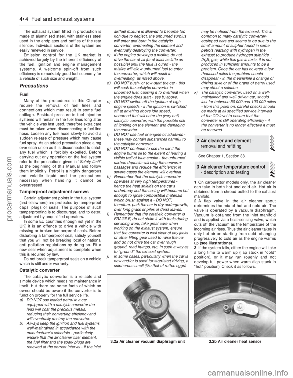
2A flap valve in the air cleaner spout
determines the mix of hot and cold air. The
valve is operated by a vacuum diaphragm.
Vacuum is obtained from the inlet manifold
and is applied via a heat-sensing valve, which
cuts off the vacuum as the temperature of the
incoming air rises. Thus the air cleaner takes in
only hot air on starting from cold, changing
progressively to cold air as the engine warms
up (see illustrations).
3If the system fails, either the engine will take
a long time to warm up (flap stuck in “cold”
position), or it may run roughly and not
develop full power when warm (flap stuck in
“hot” position). Check it as follows.
3Air cleaner temperature control
- description and testing
2Air cleaner and element -
removal and refitting
4•4Fuel and exhaust systems
3.2b Air cleaner heat sensor3.2a Air cleaner vacuum diaphragm unit
procarmanuals.com
Page 98 of 255
4With the engine cold, disconnect the cold
air inlet trunking from the spout. Look into the
spout and check that the flap valve is covering
the hot air inlet.
5Start the engine and allow it to idle. Check
that the flap moves to cover the cold air inlet. If
the flap does not move, check the diaphragm
and heat sensor as follows.
6Stop the engine. Disconnect the diaphragm
vacuum pipe from the heat sensor. Apply
vacuum to the diaphragm, using a vacuum
head pump or by connecting the pipe directly
to manifold vacuum. If the flap now moves, the
heat sensor or vacuum line was faulty. If the
flap still does not move, the diaphragm is
faulty or the flap is jammed.
7On completion reconnect the vacuum pipe
and the cold air trunking.
Mechanical
1Carburettor models without air conditioning
are fitted with a mechanical fuel pump, located
on the left-hand side of the engine block.
2To test the pump, disconnect the ignition
coil LT lead. Disconnect the outlet hose from
the pump and place a wad of rag next to the
pump outlet. Take appropriate fire
precautions.
3Have an assistant crank the engine on the
starter. Well-defined spurts of fuel must beejected from the pump outlet - if not, the pump
is probably faulty (or the tank is empty).
Dispose of the fuel-soaked rag safely.
4To remove the fuel pump, first disconnect
the battery negative lead.
5Disconnect and plug the pump inlet and
outlet hoses. Be prepared for fuel spillage.
6Unscrew the two bolts and withdraw the
pump from the cylinder block. Remove the
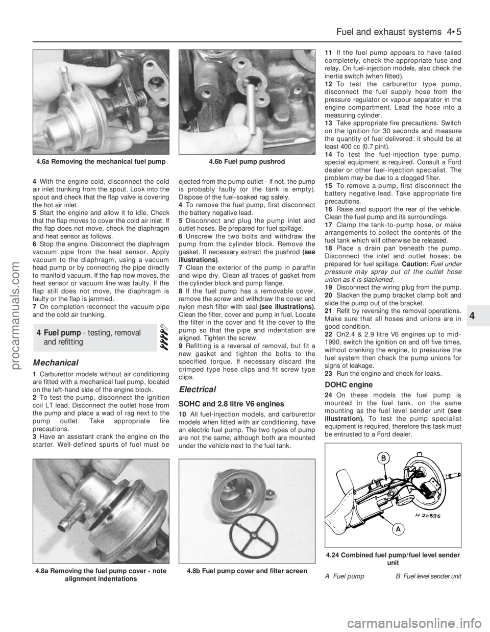
gasket. If necessary extract the pushrod (see
illustrations).
7Clean the exterior of the pump in paraffin
and wipe dry. Clean all traces of gasket from
the cylinder block and pump flange.
8If the fuel pump has a removable cover,
remove the screw and withdraw the cover and
nylon mesh filter with seal (see illustrations).
Clean the filter, cover and pump in fuel. Locate
the filter in the cover and fit the cover to the
pump so that the pipe and indentation are
aligned. Tighten the screw.
9Refitting is a reversal of removal, but fit a
new gasket and tighten the bolts to the
specified torque. If necessary discard the
crimped type hose clips and fit screw type
clips.
Electrical
SOHC and 2.8 litre V6 engines
10All fuel-injection models, and carburettor
models when fitted with air conditioning, have
an electric fuel pump. The two types of pump
are not the same, although both are mounted
under the vehicle next to the fuel tank.11If the fuel pump appears to have failed
completely, check the appropriate fuse and
relay. On fuel-injection models, also check the
inertia switch (when fitted).
12To test the carburettor type pump,
disconnect the fuel supply hose from the
pressure regulator or vapour separator in the
engine compartment. Lead the hose into a
measuring cylinder.
13Take appropriate fire precautions. Switch
on the ignition for 30 seconds and measure
the quantity of fuel delivered: it should be at
least 400 cc (0.7 pint).
14To test the fuel-injection type pump,
special equipment is required. Consult a Ford
dealer or other fuel-injection specialist. The
problem may be due to a clogged filter.
15To remove a pump, first disconnect the
battery negative lead. Take appropriate fire
precautions.
16Raise and support the rear of the vehicle.
Clean the fuel pump and its surroundings.
17Clamp the tank-to-pump hose, or make
arrangements to collect the contents of the
fuel tank which will otherwise be released.
18Place a drain pan beneath the pump.
Disconnect the inlet and outlet hoses; be
prepared for fuel spillage. Caution: Fuel under
pressure may spray out of the outlet hose
union as it is slackened.
19Disconnect the wiring plug from the pump.
20Slacken the pump bracket clamp bolt and
slide the pump out of the bracket.
21Refit by reversing the removal operations.
Make sure that all hoses and unions are in
good condition.
22On2.4 & 2.9 litre V6 engines up to mid-
1990, switch the ignition on and off five times,
without cranking the engine, to pressurise the
fuel system then check the pump unions for
signs of leakage.
23Run the engine and check for leaks.
DOHC engine
24On these models the fuel pump is
mounted in the fuel tank, on the same
mounting as the fuel level sender unit(see
illustration).To test the pump specialist
equipment is required, therefore this task must
be entrusted to a Ford dealer.
4Fuel pump - testing, removal
and refitting
Fuel and exhaust systems 4•5
4
4.6a Removing the mechanical fuel pump4.6b Fuel pump pushrod
4.8a Removing the fuel pump cover - note
alignment indentations4.8b Fuel pump cover and filter screenA Fuel pumpB Fuel level sender unit
4.24 Combined fuel pump/fuel level sender
unit
procarmanuals.com
Page 101 of 255
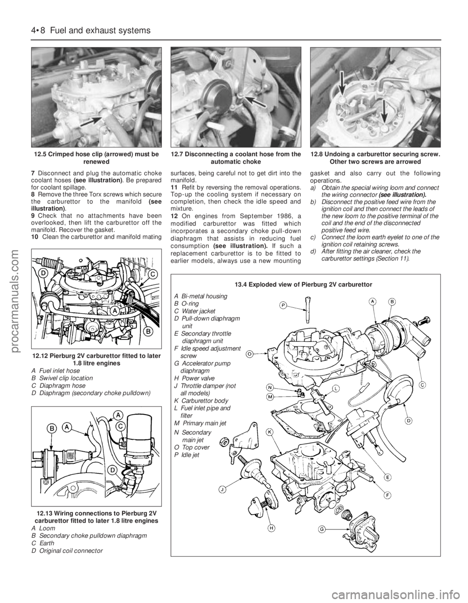
7Disconnect and plug the automatic choke
coolant hoses (see illustration). Be prepared
for coolant spillage.
8Remove the three Torx screws which secure
the carburettor to the manifold (see
illustration).
9Check that no attachments have been
overlooked, then lift the carburettor off the
manifold. Recover the gasket.
10Clean the carburettor and manifold matingsurfaces, being careful not to get dirt into the
manifold.
11Refit by reversing the removal operations.
Top-up the cooling system if necessary on
completion, then check the idle speed and
mixture.
12On engines from September 1986, a
modified carburettor was fitted which
incorporates a secondary choke pull-down
diaphragm that assists in reducing fuel
consumption (see illustration).If such a
replacement carburettor is to be fitted to
earlier models, always use a new mountinggasket and also carry out the following
operations.
a)Obtain the special wiring loom and connect
the wiring connector(see illustration).
b)Disconnect the positive feed wire from the
ignition coil and then connect the leads of
the new loom to the positive terminal of the
coil and the end of the disconnected
positive feed wire.
c)Connect the loom earth eyelet to one of the
ignition coil retaining screws.
d)After fitting the air cleaner, check the
carburettor settings (Section 11).
4•8Fuel and exhaust systems
12.5 Crimped hose clip (arrowed) must be
renewed
12.12 Pierburg 2V carburettor fitted to later
1.8 litre engines
A Fuel inlet hose
B Swivel clip location
C Diaphragm hose
D Diaphragm (secondary choke pulldown)
12.13 Wiring connections to Pierburg 2V
carburettor fitted to later 1.8 litre engines
A Loom
B Secondary choke pulldown diaphragm
C Earth
D Original coil connector
12.7 Disconnecting a coolant hose from the
automatic choke12.8 Undoing a carburettor securing screw.
Other two screws are arrowed
13.4 Exploded view of Pierburg 2V carburettor
A Bi-metal housing
B O-ring
C Water jacket
D Pull-down diaphragm
unit
E Secondary throttle
diaphragm unit
F Idle speed adjustment
screw
G Accelerator pump
diaphragm
H Power valve
J Throttle damper (not
all models)
K Carburettor body
L Fuel inlet pipe and
filter
M Primary main jet
N Secondary
main jet
O Top cover
P Idle jet
procarmanuals.com
Page 103 of 255
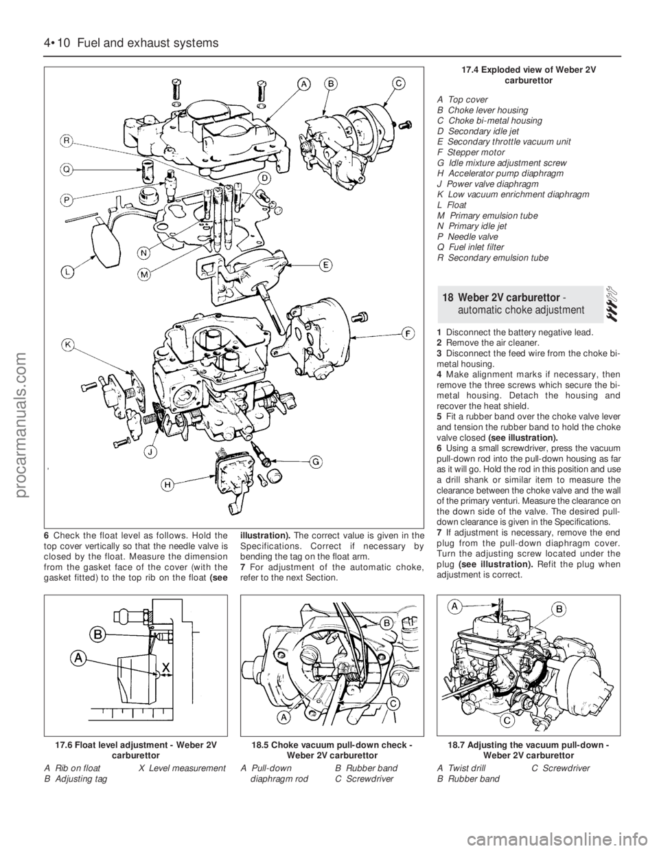
6Check the float level as follows. Hold the
top cover vertically so that the needle valve is
closed by the float. Measure the dimension
from the gasket face of the cover (with the
gasket fitted) to the top rib on the float(seeillustration).The correct value is given in the
Specifications. Correct if necessary by
bending the tag on the float arm.
7For adjustment of the automatic choke,
refer to the next Section.1Disconnect the battery negative lead.
2Remove the air cleaner.
3Disconnect the feed wire from the choke bi-
metal housing.
4Make alignment marks if necessary, then
remove the three screws which secure the bi-
metal housing. Detach thehousing and
recover the heat shield.
5Fit a rubber band over the choke valve lever
and tension the rubber band to hold the choke
valve closed(see illustration).
6Using a small screwdriver, press the vacuum
pull-down rod into the pull-down housing as far
as it will go. Hold the rod in this position and use
a drill shank or similar item to measure the
clearance between the choke valve and the wall
of the primary venturi. Measure the clearance on
the down side of the valve. The desired pull-
down clearance is given in the Specifications.
7If adjustment is necessary, remove the end
plug from the pull-down diaphragm cover.
Turn the adjusting screw located under the
plug (see illustration).Refit the plug when
adjustment is correct.
18Weber 2V carburettor -
automatic choke adjustment
4•10Fuel and exhaust systems
17.6 Float level adjustment - Weber 2V
carburettor
A Rib on float
B Adjusting tagX Level measurement
18.5 Choke vacuum pull-down check -
Weber 2V carburettor
A Pull-down
diaphragm rodB Rubber band
C Screwdriver
18.7 Adjusting the vacuum pull-down -
Weber 2V carburettor
A Twist drill
B Rubber bandC Screwdriver
17.4 Exploded view of Weber 2V
carburettor
A Top cover
B Choke lever housing
C Choke bi-metal housing
D Secondary idle jet
E Secondary throttle vacuum unit
F Stepper motor
G Idle mixture adjustment screw
H Accelerator pump diaphragm
J Power valve diaphragm
K Low vacuum enrichment diaphragm
L Float
M Primary emulsion tube
N Primary idle jet
P Needle valve
Q Fuel inlet filter
R Secondary emulsion tube
procarmanuals.com
Page 107 of 255
16Start the engine and note the engine
speed (rpm). The engine speed should
increase above the normal idle speed, and
should be as given in the Specifications.
17If the engine speed is not as specified,
remove the tamperproof plug from the top of
the throttle kicker housing, and turn the
adjustment screw to give the specified speed.
18On completion of adjustment, fit a new
tamperproof cap.
19Disconnect the tubing from the inlet
manifold, and reconnect the throttle kicker
vacuum hose.
20Refit the plastic shield and the air cleaner.
On 2.4 & 2.9 litre V6 models especially,
residual pressure will remain in the fuel lines
long after the vehicle was last used therefore
the fuel system must be depressurised before
any hose is disconnected; the system is
depressurised via the vent valve on the fuel
rail, noting that it may be necessary to depress
the valve several times before the pressure is
fully released. As an added precaution place a
rag over the valve as it is depressed to catch
any fuel which is forcibly expelled. Before
carrying out any operation on the fuel system
refer to the precautions given in Safety first! at
the beginning of this Manual and follow them
implicitly. Petrol is a highly dangerous and
volatile liquid and the precautions necessary
when handling it cannot be overstressed.
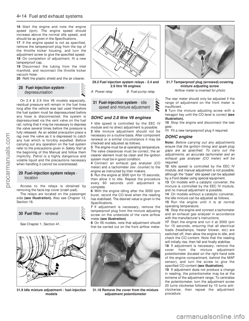
Access to the relays is obtained by
removing the facia top cover (crash pad).
The relays are located on the passenger
side(see illustration). Also see Chapter 13,
Section 16.
See Chapter 1, Section 41.
SOHC and 2.8 litre V6 engines
1Idle speed is controlled by the EEC IV
module and no direct adjustment is possible.
2Idle mixture adjustment should not be
necessary on a routine basis. After component
renewal or a similar circumstance it may be
checked and adjusted as follows.
3The engine must be at operating temperature.
The valve clearances must be correct, the air
cleaner element must be clean and the ignition
system must be in good condition.
4Connect an exhaust gas analyser (CO
meter) and a tachometer (rev. counter) to the
engine as instructed by their makers.
5Run the engine at 3000 rpm for 15 seconds,
then allow it to idle. Repeat the procedure
every 60 seconds until adjustment is
complete.
6With the engine idling after the 3000 rpm
burst, record the CO level when the reading
has stabilised. The desired value is given in the
Specifications.
7If adjustment is necessary, remove the
tamperproof plug from the mixture adjusting
screw on the underside of the vane airflow
meter (see illustration).
8On V6 models, note that adjustment should
first be carried out on the front airflow meter.The rear meter should only be adjusted if the
range of adjustment on the front meter is
insufficient.
9Turn the mixture adjusting screw with a
hexagon key until the CO level is correct (see
illustration).
10Stop the engine and disconnect the test
gear.
11Fit a new tamperproof plug if required.
DOHC engine
Note: Before carrying out any adjustments
ensure that the ignition timing and spark plug
gaps are as specified. To carry out the
adjustments, an accurate tachometer and an
exhaust gas analyser (CO meter) will be
required.
12Idle speed is controlled by the EEC IV
module, and manual adjustment is not possible,
although the “base” idle speed can be adjusted
by a Ford dealer using special equipment.
13On models with a catalytic converter, the
mixture is controlled by the EEC IV module,
and no manual adjustment is possible.
14On models without a catalytic converter,
the idle mixture can be adjusted as follows.
15Run the engine until it is at normal
operating temperature.
16Stop the engine and connect a tachometer
and an exhaust gas analyser in accordance
with the manufacturer’s instructions.
17Start the engine and run it at 3000 rpm
for 15 seconds, ensuring that all electrical
loads (headlamps, heater blower, etc) are
switched off, then allow the engine to idle, and
check the CO content. Note that the reading
will initially rise, then fall and finally stabilise.
18If adjustment is necessary, remove the
cover from the mixture adjustment
potentiometer (located on the right-hand side
of the engine compartment, behind the MAP
sensor), and turn the screw to give the
specified CO content (see illustration).
19If adjustment does not produce a change
in reading, the potentiometer may be at the
extreme of the adjustment range. To centralise
the potentiometer, turn the adjustment screw
20 turns clockwise followed by 10 turns anti-
clockwise, then repeat the adjustment
procedure.
31Fuel-injection system - idle
speed and mixture adjustment
30Fuel filter - renewal
29Fuel-injection system relays -
location
28Fuel-injection system -
depressurisation
4•14Fuel and exhaust systems
31.18 Remove the cover from the mixture
adjustment potentiometer31.9 Idle mixture adjustment - fuel-injection
models
29.2 Fuel injection system relays - 2.4 and
2.9 litre V6 engines
A Power relayB Fuel pump relay
31.7 Tamperproof plug (arrowed) covering
mixture adjusting screw
Airflow meter is inverted for photo
procarmanuals.com
Page 128 of 255
2Disconnect the battery negative lead.
3Drain the cooling system (Chapter 3). Save
the coolant if it is fit for re-use.
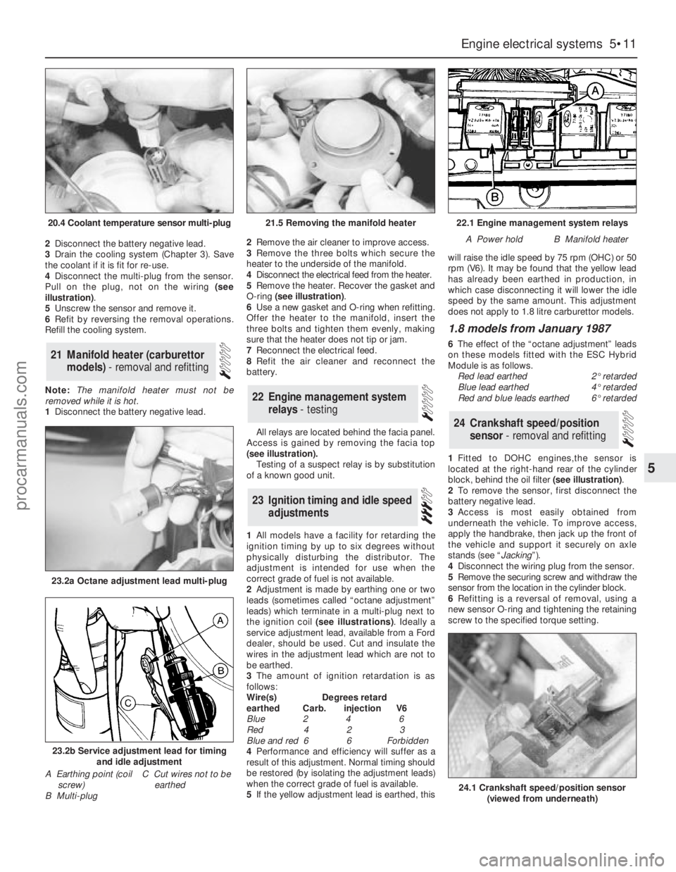
4Disconnect the multi-plug from the sensor.
Pull on the plug, not on the wiring (see
illustration).
5Unscrew the sensor and remove it.
6Refit by reversing the removal operations.
Refill the cooling system.
Note: The manifold heater must not be
removed while it is hot.
1Disconnect the battery negative lead. 2Remove the air cleaner to improve access.
3Remove the three bolts which secure the
heater to the underside of the manifold.
4Disconnect the electrical feed from the heater.
5Remove the heater. Recover the gasket and
O-ring (see illustration).
6Use a new gasket and O-ring when refitting.
Offer the heater to the manifold, insert the
three bolts and tighten them evenly, making
sure that the heater does not tip or jam.
7Reconnect the electrical feed.
8Refit the air cleaner and reconnect the
battery.
All relays are located behind the facia panel.
Access is gained by removing the facia top
(see illustration).
Testing of a suspect relay is by substitution
of a known good unit.
1All models have a facility for retarding the
ignition timing by up to six degrees without
physically disturbing the distributor. The
adjustment is intended for use when the
correct grade of fuel is not available.
2Adjustment is made by earthing one or two
leads (sometimes called “octane adjustment”
leads) which terminate in a multi-plug next to
the ignition coil (see illustrations). Ideally a
service adjustment lead, available from a Ford
dealer, should be used. Cut and insulate the
wires in the adjustment lead which are not to
be earthed.
3The amount of ignition retardation is as
follows:
Wire(s) Degrees retard
earthed Carb. injection V6
Blue 2 4 6
Red 4 2 3
Blue and red 6 6 Forbidden
4Performance and efficiency will suffer as a
result of this adjustment. Normal timing should
be restored (by isolating the adjustment leads)
when the correct grade of fuel is available.
5If the yellow adjustment lead is earthed, thiswill raise the idle speed by 75 rpm (OHC) or 50
rpm (V6). It may be found that the yellow lead
has already been earthed in production, in
which case disconnecting it will lower the idle
speed by the same amount. This adjustment
does not apply to 1.8 litre carburettor models.
1.8 models from January 1987
6The effect of the “octane adjustment” leads
on these models fitted with the ESC Hybrid
Module is as follows.
Red lead earthed2°retarded
Blue lead earthed4°retarded
Red and blue leads earthed6°retarded
1Fitted to DOHC engines,the sensor is
located at the right-hand rear of the cylinder
block, behind the oil filter (see illustration).
2To remove the sensor, first disconnect the
battery negative lead.
3Access is most easily obtained from
underneath the vehicle. To improve access,
apply the handbrake, then jack up the front of
the vehicle and support it securely on axle
stands (see “Jacking”).
4Disconnect the wiring plug from the sensor.
5Remove the securing screw and withdraw the
sensor from the location in the cylinder block.
6Refitting is a reversal of removal, using a
new sensor O-ring and tightening the retaining
screw to the specified torque setting.
24Crankshaft speed/position
sensor - removal and refitting
23Ignition timing and idle speed
adjustments
22Engine management system
relays - testing
21Manifold heater (carburettor
models) - removal and refitting
Engine electrical systems 5•11
5
20.4 Coolant temperature sensor multi-plug21.5 Removing the manifold heater22.1 Engine management system relays
A Power holdB Manifold heater
23.2a Octane adjustment lead multi-plug
23.2b Service adjustment lead for timing
and idle adjustment
A Earthing point (coil
screw)
B Multi-plugC Cut wires not to be
earthed
24.1 Crankshaft speed/position sensor
(viewed from underneath)
procarmanuals.com
Page 142 of 255
3If the servo unit still fails to operate
satisfactorily the fault lies within the unit itself.
Repairs to the unit are not possible.
4Remove the master cylinder (Section 27).
5Disconnect the vacuum hose from the servo
unit taking care not to displace the rubber
sealing grommet. Disconnect the wiring plug
from the Pedal Travel Sensor (PTS) which is
situated on the front of the servo.
6Working from inside the vehicle, remove the
servo pushrod retaining clip from the brake
pedal. If necessary, to improve access to the
brake pedal remove the right-hand lower facia
panel .
7Slacken and remove the four nuts securing
the servo unit to the bulkhead, then return to
the engine compartment and remove the
servo unit from the vehicle. Remove the
gasket from the rear of the unit and discard it.
8Note that the vacuum servo unit is a sealed
assembly with no spare parts available
separately. Therefore if it is faulty it must be
renewed as a unit. Inspect the vacuum servo
vacuum hose sealing grommet for damage or
deterioration and renew if necessary.
9Remove all traces of dirt from the servo unit
and bulkhead mating surfaces and fit a new
gasket onto the rear of the servo.
10Manoeuvre the servo unit into position,
ensuring that the servo unit pushrod is
correctly located with the hole in the pedal.
Refit the servo unit retaining nuts and tighten
them to the specified torque setting. Secure
the pushrod in position with the retaining clip
11Carefully refit the vacuum hose to the servo
unit taking great care not to damage or displace
the sealing grommet. Reconnect the wiring
connector to the Pedal Travel Sensor (PTS).
12Refit the master cylinder as described
above. On completion start the engine and
check the operation of the servo unit.
1Disconnect the vacuum hose from the servo
unit taking care not to displace the rubber
sealing grommet.
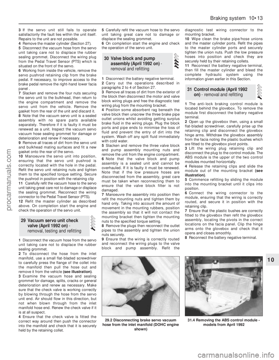
2To disconnect the hose from the inlet
manifold, use a small flat-bladed screwdriver
to carefully press the flange of the collet into
the manifold then pull the hose out and
remove it from the vehicle (see illustration).
3Examine the vacuum hose and sealing
grommet for damage, splits, cracks or general
deterioration and renew as necessary. Make
sure that the check valve is working correctly
by blowing through the hose from the servo
unit end. Air should flow in this direction, but
not when blown through from the inlet
manifold hose end. Renew the check valve if it
is at all suspect.
4Ensure that the check valve is fitted the
correct way around then push the connector
into the manifold and check that it is securely
held by the retaining collet.5Carefully refit the vacuum hose to the servo
unit taking great care not to damage or
displace the sealing grommet.
6On completion start the engine and check
the operation of the servo unit.
1Disconnect the battery negative terminal.
2Carry out the operations described in
paragraphs 2 to 4 of Section 27.
3Remove all traces of dirt from the exterior of
the block then disconnect the motor and valve
block wiring plugs and free the diagnostic test
wiring plug from the mounting bracket.
4Position some absorbent rag beneath the
valve block then unscrew the three brake pipe
outlet unions whilst avoiding getting surplus
brake fluid in the wiring plugs. Plug the block
ports and pipe ends to minimise the loss of
fluid and prevent the entry of dirt into the
system. Wash off any spilt fluid immediately
with cold water.
5Slacken and remove the three valve block
and pump assembly mounting nuts and
remove the unit from the engine compartment.
6Note that the valve block and pump
assembly is a sealed unit and cannot be
overhauled. If it is faulty it must be renewed.
Note that if the low pressure hoses are
disconnected from the assembly, great care
must be taken when reconnecting them to
ensure that the valve block filter is not
damaged.
7Manoeuvre the assembly into position then
refit the mounting nuts and tighten them by
hand only. Taking into account the amount of
movement in the mounting rubbers, position
the assembly so that it will not contact the
mounting bracket then tighten the mounting
nuts to the specified torque setting.
8Remove the plugs then reconnect the outlet
pipes to the assembly and tighten the union
nuts securely.
9Ensure that the wiring is correctly routed
and reconnect the wiring plugs to the valve
block and pump assembly. Refit thediagnostic test wiring connector to the
mounting bracket.
10Wipe clean the brake pipe/hose unions
and the master cylinder ports. Refit the pipes
to the master cylinder ports and securely
tighten the union nuts. Push the low pressure
hoses into position and check they are
securely held by their retaining collets.
11Reconnect the battery negative terminal,
then fill the master cylinder and bleed the
complete hydraulic system using the
information given earlier in this Section.
1The anti-lock braking control module is
located behind the glovebox. To remove the
module first disconnect the battery negative
terminal.
2Open up the glovebox then, using a small
flat-bladed screwdriver, carefully prise up the
retaining clip and disconnect the glovebox
hinge arms. Withdraw the glovebox assembly
from the facia noting the plastic bushes which
are fitted to the glovebox pivot points.
3Lift the wiring plug retaining clip and
disconnect the plug to the control module. The
ABS module is the upper of the two control
modules mounted horizontally.
4Release the retaining clips and slide the
module out of the mounting bracket (see
illustration).
5Commence refitting by sliding the module
into the mounting bracket until it clips into
position.
6Connect the wiring connector to the
module, ensuring that the wiring is correctly
routed, and secure it in position with the
retaining clip.
7Ensure that the plastic bushes are correctly
fitted to the glovebox then refit the glovebox
assembly, locating the pivots in the correct
locations on the facia panel. Clip the hinge
arms onto the glovebox and check that it
opens and closes smoothly.
8Reconnect the battery negative terminal.
31Control module (April 1992
on) - removal and refitting
30Valve block and pump
assembly (April 1992 on) -
removal and refitting
29 Vacuum servo unit check
valve (April 1992 on) -
removal, testing and refitting
Braking system 10•13
10
29.2 Disconnecting brake servo vacuum
hose from the inlet manifold (DOHC engine
shown)31.4 Removing the ABS control module -
models from April 1992
procarmanuals.com