1985 FORD GRANADA air filter
[x] Cancel search: air filterPage 51 of 255
together, guide the torque converter studs
through the holes in the driveplate. When the
engine is positioned flush with the engine
adapter plate and the transmission housing,
check that the torque converter is free to move
axially a small amount before refitting and
tightening the engine-to-transmission bolts.
6Do not tighten the torque converter-to-
driveplate nuts until the lower engine-to-
transmission bolts have been fitted and
tightened.
7Ensure that the roadwheels and the steering
wheel are in the straight-ahead position then
align the marks made on removal and
reconnect the intermediate shaft to the
steering gearing. Tighten the clamp bolt to the
specified torque.
8Reconnect the selector rod and adjust as
described in Chapter 7, PartB.
9Refit the propeller shaft.
10Refit the exhaust system.
11Fill the engine with the correct grade and
quantity of oil.
12Check the throttle cable adjustment. Where
necessary, also adjust the speed control cable
in the same way so that there is only a small
amount of slack present in the cable.
13Reconnect the coolant hoses to the water
pump housing.
14Fill the cooling system.
15Check and if necessary top-up the
transmission fluid level.
16Tighten all fixings to the specified torque,
where applicable.
Proceed as described in Part A, Section 23
of this Chapter but note that on certain
models, it may be necessary to unbolt the
engine mounting brackets from the cylinder
block to allow sufficient clearance to remove
the mountings.
1Refer to Part A, Section 8 of this Chapter,
paragraphs 1 to 8 inclusive.
2A selection of splined and Torx sockets will
be required to remove many of the bolts when
dismantling the engine.
3Before dismantling the main engine
components, the following externally mounted
ancillary components can be removed.
a)Inlet manifold (and carburettor, where
applicable).
b)Exhaust manifold.
c)Alternator.
d)Water pump, and thermostat.
e)Water pump/alternator drivebelt tensioner.
f)Distributor cap, HT leads and spark plugs.
g)Oil pressure warning lamp switch.
h)Crankshaft speed/position sensor.
i)Oil filter.
j)Dipstick.
k)Engine mounting brackets (if not already
done).
l)Crankcase ventilation pipe and hoses.m)Clutch.
n)Alternator mounting bracket.
o)Air conditioning compressor mounting
bracket (where applicable).
p)Engine lifting brackets.
Note: A puller will be required to remove the
crankshaft pulley. A new crankshaft pulley bolt,
a new timing chain tensioner plunger
assembly, new upper and lower timing chain
cover gaskets and a new camshaft cover
gasket and reinforcing sleeve sealing rings
must be used on refitting.
1If the engine is in the car, carry out thefollowing operations.
a)Disconnect the battery negative lead.
b)To improve access, remove the radiator. It
will be difficult to remove the crankshaft
pulley with the radiator in place.
c)On carburettor models, remove the air
cleaner.
d)On fuel-injection models, remove the air
inlet hose, plenum chamber and air
cleaner lid as an assembly.
e)Disconnect the breather hose from the
camshaft cover.
f)Remove the distributor cap and HT leads,
and the rotor arm and housing.
2Proceed as described in paragraphs 2 to 11
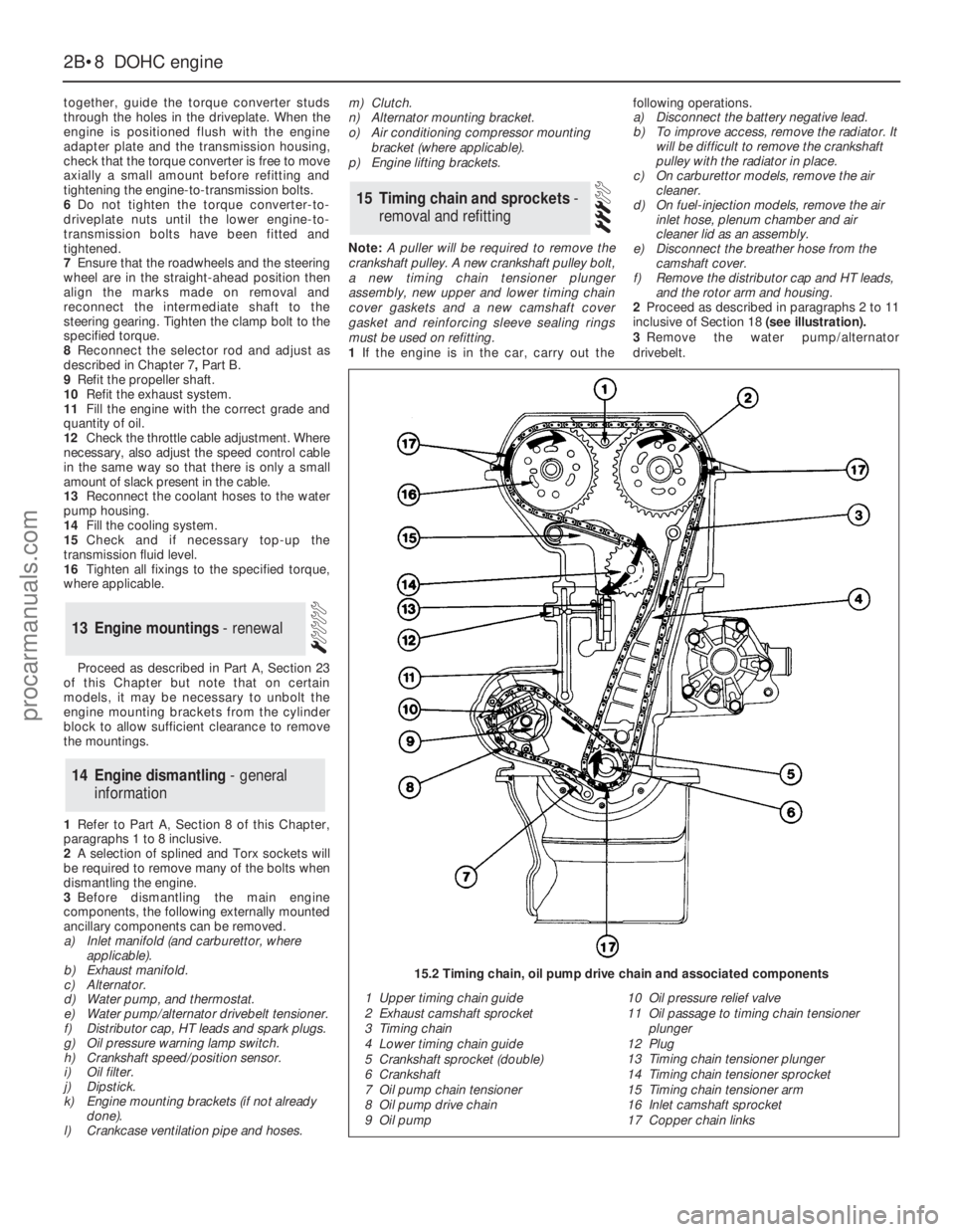
inclusive of Section 18 (see illustration).
3Remove the water pump/alternator
drivebelt.
15Timing chain and sprockets -
removal and refitting
14Engine dismantling - general
information
13Engine mountings - renewal
2B•8DOHCengine
1 Upper timing chain guide
2 Exhaust camshaft sprocket
3 Timing chain
4 Lower timing chain guide
5 Crankshaft sprocket (double)
6 Crankshaft
7 Oil pump chain tensioner
8 Oil pump drive chain
9 Oil pump10 Oil pressure relief valve
11 Oil passage to timing chain tensioner
plunger
12 Plug
13 Timing chain tensioner plunger
14 Timing chain tensioner sprocket
15 Timing chain tensioner arm
16 Inlet camshaft sprocket
17 Copper chain links
15.2 Timing chain, oil pump drive chain and associated components
procarmanuals.com
Page 62 of 255
Chapter 2 Part C:
2.4, 2.8 and 2.9 litre V6 engines
Ancillary components - refitting . . . . . . . . . . . . . . . . . . . . . . . . . . . .40
Ancillary components - removal . . . . . . . . . . . . . . . . . . . . . . . . . . . . .7
Camshaft and bearings - examination and renovation . . . . . . . . . .22
Camshaft and intermediate plate - refitting . . . . . . . . . . . . . . . . . . .32
Camshaft and intermediate plate - removal . . . . . . . . . . . . . . . . . . .14
Compression test - description and interpretation . . . . . . . . . . . . .43
Crankcase ventilation system - general information . . . . . . . . . . . .29
Crankshaft and bearings - examination . . . . . . . . . . . . . . . . . . . . . .26
Crankshaft and main bearings - refitting . . . . . . . . . . . . . . . . . . . . .31
Crankshaft and main bearings - removal . . . . . . . . . . . . . . . . . . . . .15
Crankshaft front oil seal - renewal . . . . . . . . . . . . . . . . . . . . . . . . . .17
Crankshaft rear oil seal - renewal . . . . . . . . . . . . . . . . . . . . . . . . . . .18
Cylinder bores - examination and renovation . . . . . . . . . . . . . . . . .24
Cylinder heads - overhaul . . . . . . . . . . . . . . . . . . . . . . . . . . . . . . . .23
Cylinder heads - refitting . . . . . . . . . . . . . . . . . . . . . . . . . . . . . . . . .38
Cylinder heads - removal . . . . . . . . . . . . . . . . . . . . . . . . . . . . . . . . . .8
Engine - refitting . . . . . . . . . . . . . . . . . . . . . . . . . . . . . . . . . . . . . . . .41
Engine - removal . . . . . . . . . . . . . . . . . . . . . . . . . . . . . . . . . . . . . . . .5
Engine dismantling - general . . . . . . . . . . . . . . . . . . . . . . . . . . . . . . .6
Engine mountings - renewal . . . . . . . . . . . . . . . . . . . . . . . . . . . . . . .16
Engine reassembly - general information . . . . . . . . . . . . . . . . . . . . .30
Examination and renovation - general infomation . . . . . . . . . . . . . .19Flywheel/driveplate and adapter plate - refitting . . . . . . . . . . . . . . .35
Flywheel/driveplate and adapter plate - removal . . . . . . . . . . . . . . .11
Flywheel ring gear - examination and renovation . . . . . . . . . . . . . . 28
General information . . . . . . . . . . . . . . . . . . . . . . . . . . . . . . . . . . . . . .1
Initial start-up after overhaul or major repair . . . . . . . . . . . . . . . . . .42
Major operations possible with the engine in the vehicle . . . . . . . . .2
Major operations requiring engine removal . . . . . . . . . . . . . . . . . . . .3
Methods of engine removal . . . . . . . . . . . . . . . . . . . . . . . . . . . . . . . .4
Oil pump - dismantling, examination and reassembly . . . . . . . . . . .27
Oil pump - refitting . . . . . . . . . . . . . . . . . . . . . . . . . . . . . . . . . . . . . .34
Oil pump - removal . . . . . . . . . . . . . . . . . . . . . . . . . . . . . . . . . . . . . .12
Pistons and connecting rods - examination and renovation . . . . . .25
Pistons and connecting rods - refitting . . . . . . . . . . . . . . . . . . . . . .33
Pistons and connecting rods - removal . . . . . . . . . . . . . . . . . . . . . .13
Rocker shaft - dismantling, examination and reassembly . . . . . . . .20
Sump - refitting . . . . . . . . . . . . . . . . . . . . . . . . . . . . . . . . . . . . . . . . .37
Sump - removal . . . . . . . . . . . . . . . . . . . . . . . . . . . . . . . . . . . . . . . . .9
Tappets and pushrods - examination . . . . . . . . . . . . . . . . . . . . . . .21
Timing cover and drive - refitting . . . . . . . . . . . . . . . . . . . . . . . . . . .36
Timing cover and drive - removal . . . . . . . . . . . . . . . . . . . . . . . . . . .10
Valve clearances - checking and adjustment . . . . . . . . . . . . . . . . . .39
2.8 litre engine
General
Manufacturer’s code . . . . . . . . . . . . . . . . . . . . . . . . . . . . . . . . . . . . . . . . PRE
Bore - mm (in) . . . . . . . . . . . . . . . . . . . . . . . . . . . . . . . . . . . . . . . . . . . . . 93.0 (3.66)
Stroke - mm (in) . . . . . . . . . . . . . . . . . . . . . . . . . . . . . . . . . . . . . . . . . . . 68.5 (2.70)
Cubic capacity - cc (cu in) . . . . . . . . . . . . . . . . . . . . . . . . . . . . . . . . . . . 2792 (170)
Compression ratio . . . . . . . . . . . . . . . . . . . . . . . . . . . . . . . . . . . . . . . . . 9.2:1
Compression pressure at cranking speed . . . . . . . . . . . . . . . . . . . . . . . 11.5 to 12.5 bar (167 to 181 lbf/in
2)
Maximum power (DIN, kW @ rpm) . . . . . . . . . . . . . . . . . . . . . . . . . . . . . 110 @ 5800
Maximum torque (DIN, Nm @ rpm) . . . . . . . . . . . . . . . . . . . . . . . . . . . . . 216 @ 3000
Lubrication system
Oil type . . . . . . . . . . . . . . . . . . . . . . . . . . . . . . . . . . . . . . . . . . . . . . . . . . See “Lubricants and fluids”
Oil capacity (drain and refill, including filter) . . . . . . . . . . . . . . . . . . . . . . 4.25 litres (7.5 pints) approx
Oil pressure (SAE 10W/30 oil at 80°C/176°F):
At 750 rpm . . . . . . . . . . . . . . . . . . . . . . . . . . . . . . . . . . . . . . . . . . . . . 1.0 bar
At 2000 rpm . . . . . . . . . . . . . . . . . . . . . . . . . . . . . . . . . . . . . . . . . . . . 2.5 bar
Oil pressure relief valve opening pressure . . . . . . . . . . . . . . . . . . . . . . . 4.0 to 4.7 bar
Oil pressure warning light switch setting . . . . . . . . . . . . . . . . . . . . . . . . 0.3 to 0.5 bar
2C•1
Easy,suitable for
novice with little
experienceFairly easy,suitable
for beginner with
some experienceFairly difficult,
suitable for competent
DIY mechanicDifficult,suitable for
experienced DIY
mechanicVery difficult,
suitable for expert
DIY or professional
Degrees of difficulty
Specifications Contents
2C
procarmanuals.com
Page 67 of 255
The V6 engine fitted to the Granada is only
available in fuel-injected form. Mechanically,
the design of the engine is well-established,
and it is improved by the latest fuel, ignition and
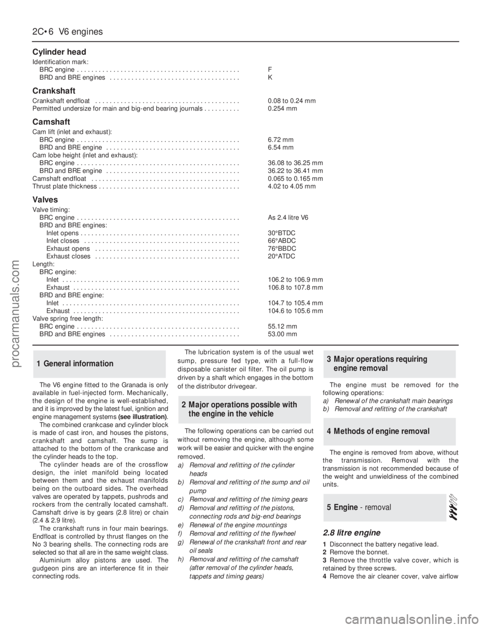
engine management systems (see illustration).
The combined crankcase and cylinder block
is made of cast iron, and houses the pistons,
crankshaft and camshaft. The sump is
attached to the bottom of the crankcase and
the cylinder heads to the top.
The cylinder heads are of the crossflow
design, the inlet manifold being located
between them and the exhaust manifolds
being on the outboard sides. The overhead
valves are operated by tappets, pushrods and
rockers from the centrally located camshaft.
Camshaft drive is by gears (2.8 litre) or chain
(2.4 & 2.9 litre).
The crankshaft runs in four main bearings.
Endfloat is controlled by thrust flanges on the
No 3 bearing shells. The connecting rods are
selected so that all are in the same weight class.
Aluminium alloy pistons are used. The
gudgeon pins are an interference fit in their
connecting rods.The lubrication system is of the usual wet
sump, pressure fed type, with a full-flow
disposable canister oil filter. The oil pump is
driven by a shaft which engages in the bottom
of the distributor drivegear.
The following operations can be carried out
without removing the engine, although some
work will be easier and quicker with the engine
removed.
a)Removal and refitting of the cylinder
heads
b)Removal and refitting of the sump and oil
pump
c)Removal and refitting of the timing gears
d)Removal and refitting of the pistons,
connecting rods and big-end bearings
e)Renewal of the engine mountings
f)Removal and refitting of the flywheel
g)Renewal of the crankshaft front and rear
oil seals
h)Removal and refitting of the camshaft
(after removal of the cylinder heads,
tappets and timing gears)The engine must be removed for the
following operations:
a)Renewal of the crankshaft main bearings
b)Removal and refitting of the crankshaft
The engine is removed from above, without
the transmission. Removal with the
transmission is not recommended because of
the weight and unwieldiness of the combined
units.
2.8 litre engine
1Disconnect the battery negative lead.
2Remove the bonnet.
3Remove the throttle valve cover, which is
retained by three screws.
4Remove the air cleaner cover, valve airflow
5Engine - removal
4Methods of engine removal
3Major operations requiring
engine removal
2Major operations possible with
the engine in the vehicle
1General information
2C•6V6 engines
Cylinder head
Identification mark:
BRC engine . . . . . . . . . . . . . . . . . . . . . . . . . . . . . . . . . . . . . . . . . . . . .F
BRD and BRE engines . . . . . . . . . . . . . . . . . . . . . . . . . . . . . . . . . . . .K
Crankshaft
Crankshaft endfloat . . . . . . . . . . . . . . . . . . . . . . . . . . . . . . . . . . . . . . . .0.08 to 0.24 mm
Permitted undersize for main and big-end bearing journals . . . . . . . . . .0.254 mm
Camshaft
Cam lift (inlet and exhaust):
BRC engine . . . . . . . . . . . . . . . . . . . . . . . . . . . . . . . . . . . . . . . . . . . . .6.72mm
BRD and BRE engine . . . . . . . . . . . . . . . . . . . . . . . . . . . . . . . . . . . . .6.54 mm
Cam lobe height (inlet and exhaust):
BRC engine . . . . . . . . . . . . . . . . . . . . . . . . . . . . . . . . . . . . . . . . . . . . .36.08 to 36.25 mm
BRD and BRE engine . . . . . . . . . . . . . . . . . . . . . . . . . . . . . . . . . . . . .36.22 to 36.41 mm
Camshaft endfloat . . . . . . . . . . . . . . . . . . . . . . . . . . . . . . . . . . . . . . . . .0.065 to 0.165 mm
Thrust plate thickness . . . . . . . . . . . . . . . . . . . . . . . . . . . . . . . . . . . . . . .4.02 to 4.05 mm
Valves
Valve timing:
BRC engine . . . . . . . . . . . . . . . . . . . . . . . . . . . . . . . . . . . . . . . . . . . . .As 2.4 litre V6
BRD and BRE engines:
Inlet opens . . . . . . . . . . . . . . . . . . . . . . . . . . . . . . . . . . . . . . . . . . . .30°BTDC
Inlet closes . . . . . . . . . . . . . . . . . . . . . . . . . . . . . . . . . . . . . . . . . . .66°ABDC
Exhaust opens . . . . . . . . . . . . . . . . . . . . . . . . . . . . . . . . . . . . . . . .76°BBDC
Exhaust closes . . . . . . . . . . . . . . . . . . . . . . . . . . . . . . . . . . . . . . . .20°ATDC
Length:
BRC engine:
Inlet . . . . . . . . . . . . . . . . . . . . . . . . . . . . . . . . . . . . . . . . . . . . . . . . .106.2 to 106.9 mm
Exhaust . . . . . . . . . . . . . . . . . . . . . . . . . . . . . . . . . . . . . . . . . . . . . .106.8 to 107.8 mm
BRD and BRE engine:
Inlet . . . . . . . . . . . . . . . . . . . . . . . . . . . . . . . . . . . . . . . . . . . . . . . . .104.7 to 105.4 mm
Exhaust . . . . . . . . . . . . . . . . . . . . . . . . . . . . . . . . . . . . . . . . . . . . . .104.6 to 105.6 mm
Valve spring free length:
BRC engine . . . . . . . . . . . . . . . . . . . . . . . . . . . . . . . . . . . . . . . . . . . . .55.12 mm
BRD and BRE engines . . . . . . . . . . . . . . . . . . . . . . . . . . . . . . . . . . . .53.00 mm
procarmanuals.com
Page 68 of 255
meters and air inlet trunking. Also remove the
oil filler cap, which is connected to the
trunking by a crankcase ventilation hose.
5Release the securing clips and bolts and
remove the upper half of the fan shroud.
6Drain the cooling system and remove the
radiator.
7Disconnect the heater hoses from the
heater matrix and from the coolant outlet.
Unclip the hoses.
8Remove the fan and viscous clutch (where
fitted).
9Disconnect the following wiring:
a)Alternator
b)Temperature gauge sender
c)Engine management temperature sensor
d)Oil pressure switch
e)Idle speed control valve
f)Throttle position sensor
g)Injector nut-harness
h)Distributor multi-plug
i)Distributor-to-coil HT lead
10Disconnect the throttle cable. When
applicable, also disconnect the downshaft
cable or switch.
11Depressurise the fuel system and
disconnect the fuel supply and return lines
(see Chapter 4).
12Remove the steering pump and air
conditioning compressor drivebelts (as
applicable). Unbolt the steering pump and
compressor, move them aside within the limitsof their flexible hoses and support them by
wiring them to adjacent components.
13Remove the distributor cap and rotor.
14Remove the starter motor.
15Drain the engine oil. Unscrew the oil filter
with a strap or chain wrench and remove it; be
prepared for oil spillage.
16On manual gearbox models, disconnect
the clutch cable from the release lever.
17Unbolt the exhaust pipes from the
manifolds.
18On automatic transmission models, unbolt
the torque converter from the driveplate.
19Attach lifting tackle to the engine. If no
lifting eyes are fitted, pass ropes or chains
round the exhaust manifolds.
20Take the weight of the engine, then
remove the single nut on each side which
holds engine bearer to its mountings.
21From under the vehicle unbolt the engine
adapter plate from the bellhousing.
22Remove the engine-to-bellhousing bolts.
Also disconnect or unclip the battery negative
lead, the starter motor lead and the heat
shield.
23Support the transmission, preferably with
a trolley jack.
24Check that nothing has been overlooked,
then raise the engine and draw it forwards
clear of the transmission input shaft. Do not
allow the weight of the engine to hang on the
shaft, and do not lift the transmission by it.25With automatic transmission, make sure
that the torque converter stays engaged with
the oil pump in the transmission as the engine
is withdrawn.
26Lift the engine out of the engine bay and
take it to the bench.
2.4 & 2.9 litre engines
27The removal operations for these engines
are essentially as described for the 2.8 litre
version. Note the following points.
Coolant hoses
28Remove the hoses which run between the
thermostat housing and the water pump, and
the cooling system expansion tank.
29Remove the heater hoses which run
between the thermostat housing or coolant
distribution pipe and oil cooler (where fitted).
Vacuum hoses
30Disconnect the hose from the fuel
pressure regulator.
31Disconnect the hose from the plenum
chamber.
32Disconnect the hose from the throttle valve.
33Disconnect the hose from the T-piece
connector.
V6 engines 2C•7
2C
1.1 Exploded view of V6 engine
1 Water inlet connection
2 Thermostat
3 Water pump
4 Timing cover
5 By-pass hose flange
7 Camshaft thrust plate
8 Camshaft gear
9 Crankshaft gear
10 Flywheel
11 Crankshaft pilot
bearing
12 Oil seal
13 Oil pump drive shaft
14 Main bearing
15 Oil pump
It may be necessary to rock
the engine a little to release it
from the gearbox.
procarmanuals.com
Page 69 of 255
Other items
34Disconnect the throttle cable from the
operating lever and bracket.
35Disconnect the right-hand exhaust
downpipe from the manifold then remove the
starter motor, the oil filter, and disconnect the
left-hand exhaust downpipe, in that order.
Refer to Part A, Section 8, paragraphs 1 to 8
of this Chapter.
Cylinder head bolts on the V6 engine may
be conventional (hexagon-headed) or Torx
type. The appropriate Torx key will be needed
to deal with the latter.
Before dismantling the engine into its main
components, the following ancillaries can be
removed. The actual items removed, and the
sequence of removal, will depend on the work
to be done.
Distributor and bracket
Spark plugs
Inlet manifold and associated items
Exhaust manifolds
Clutch
Alternator and bracket
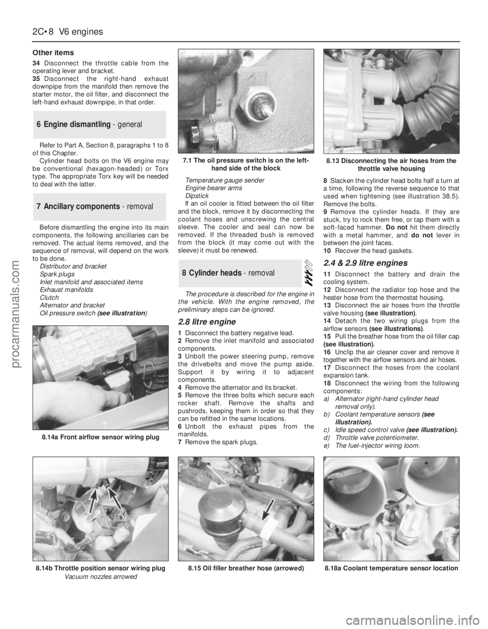
Oil pressure switch(see illustration) Temperature gauge sender
Engine bearer arms
Dipstick
If an oil cooler is fitted between the oil filter
and the block, remove it by disconnecting the
coolant hoses and unscrewing the central
sleeve. The cooler and seal can now be
removed. If the threaded bush is removed
from the block (it may come out with the
sleeve) it must be renewed.
The procedure is described for the engine in
the vehicle. With the engine removed, the
preliminary steps can be ignored.
2.8 litre engine
1Disconnect the battery negative lead.
2Remove the inlet manifold and associated
components.
3Unbolt the power steering pump, remove
the drivebelts and move the pump aside.
Support it by wiring it to adjacent
components.
4Remove the alternator and its bracket.
5Remove the three bolts which secure each
rocker shaft. Remove the shafts and
pushrods, keeping them in order so that they
can be refitted in the same locations.
6Unbolt the exhaust pipes from the
manifolds.
7Remove the spark plugs.8Slacken the cylinder head bolts half a turn at
a time, following the reverse sequence to that
used when tightening (see illustration 38.5).
Remove the bolts.
9Remove the cylinder heads. If they are
stuck, try to rock them free, or tap them with a
soft-faced hammer. Do nothit them directly
with a metal hammer, and do notlever in
between the joint faces.
10Recover the head gaskets.
2.4 & 2.9 litre engines
11Disconnect the battery and drain the
cooling system.
12Disconnect the radiator top hose and the
heater hose from the thermostat housing.
13Disconnect the air hoses from the throttle
valve housing (see illustration).
14Detach the two wiring plugs from the
airflow sensors (see illustrations).
15Pull the breather hose from the oil filler cap
(see illustration).
16Unclip the air cleaner cover and remove it
together with the airflow sensors and air hoses.
17Disconnect the hoses from the coolant
expansion tank.
18Disconnect the wiring from the following
components:
a)Alternator (right-hand cylinder head
removal only).
b)Coolant temperature sensors(see
illustration).
c)Idle speed control valve (see illustration).
d)Throttle valve potentiometer.
e)The fuel-injector wiring loom.8Cylinder heads - removal
7Ancillary components - removal
6Engine dismantling - general
2C•8V6 engines
7.1 The oil pressure switch is on the left-
hand side of the block
8.14b Throttle position sensor wiring plug
Vacuum nozzles arrowed
8.14a Front airflow sensor wiring plug
8.15 Oil filler breather hose (arrowed)8.18a Coolant temperature sensor location
8.13 Disconnecting the air hoses from the
throttle valve housing
procarmanuals.com
Page 76 of 255
Refer to Part A, Section 33 of this Chapter.
The crankcase ventilation system is very
simple. One hose joins the rear air inlet
trunking to the oil filler cap, and another hose
joins the left-hand rocker cover to the plenum
chamber. Filtered (and metered) air passes
through the oil filler cap into the engine, and is
extracted, along with any other fumes, via the
second hose. Refer to Chapter 1 for
maintenance of the system.
Refer to Part A, Section 35 of this Chapter
but disregard the reference to new cylinder
head bolts when these are of the conventional
(hexagon-headed) type. Only Torx type bolts
need to be renewed.
1Wipe the bearing shell locations in the
crankcase with a clean rag and fit the mainbearing upper half shells in position (see
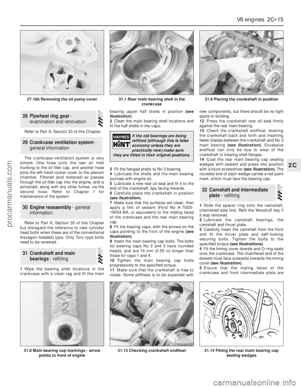
illustration).
2Clean the main bearing shell locations and
fit the half shells in the caps.
3Fit the flanged shells to No 3 bearing.
4Lubricate the shells and the main bearing
journals with engine oil.
5Lubricate a new rear oil seal and fit it to the
end of the crankshaft, lips facing inwards.
6Carefully place the crankshaft in position
(see illustration).
7Make sure that the surfaces are clean, then
apply a film of sealant (Ford No A-70SX-
19554-BA, or equivalent) to the mating faces
of the crankcase and the rear main bearing
cap.
8Fit the bearing caps, with the arrows on the
caps pointing to the front of the engine (see
illustration).
9Insert the main bearing cap bolts. The bolts
for bearing caps No 2 and 3 have rounded
heads, and are 14 mm (0.55 in) longer than
those for caps 1 and 4.
10Tighten the main bearing cap bolts
progressively to the specified torque.
11Make sure that the crankshaft is free to
rotate. Some stiffness is to be expected withnew components, but there should be no tight
spots or binding.
12Press the crankshaft rear oil seal firmly
against the rear main bearing.
13Check the crankshaft endfloat, levering
the crankshaft back and forth and inserting
feeler blades between the crankshaft and No 3
main bearing (see illustration). Excessive
endfloat can only be due to wear of the
crankshaft or bearing shell flanges.
14Coat the rear main bearing cap sealing
wedges with sealant and press into position
with a blunt screwdriver(see illustration).The
rounded end of each wedge carries a red paint
mark, which must face the bearing cap.
1Slide the spacer ring onto the camshaft,
chamfered side first. Refit the Woodruff key if
it was removed.
2Lubricate the camshaft bearings, the
camshaft and thrust plate.
3Carefully insert the camshaft from the front
and fit the thrust plate and self-locking
securing bolts. Tighten the bolts to the
specified torque (see illustrations).
4Fit the timing cover dowels and O-ring seals
onto the crankcase. The chamfered end of the
dowels must face outwards towards the timing
cover (see illustration).
5Ensure that the mating faces of the
crankcase and front intermediate plate are
32Camshaft and intermediate
plate - refitting
31Crankshaft and main
bearings - refitting
30Engine reassembly - general
information
29Crankcase ventilation system -
general information
28Flywheel ring gear -
examination and renovation
V6 engines 2C•15
2C
31.1 Rear main bearing shell in the
crankcase31.6 Placing the crankshaft in position
31.8 Main bearing cap markings - arrow
points to front of engine31.13 Checking crankshaft endfloat31.14 Fitting the rear main bearing cap
sealing wedges
27.16b Removing the oil pump cover
If the old bearings are being
refitted (although this is false
economy unless they are
practically new) make sure
they are fitted in their original positions.
procarmanuals.com
Page 82 of 255
27The inlet manifold bolts should be
retightened to the specified torque in the correct
sequence. This will mean disconnecting the air
hoses from the throttle valve housing, the
vacuum hose from the left-hand rocker cover,
and the wiring connector from the idle speed
control valve and throttle valve potentiometer.
Remove the plenum chamber, place it to one
side, then release the fuel rail bolts but do not
disconnect the fuel pipes. It may also be
necessary to remove the distributor again to
gain access to one of the bolts.
See Chapter 1, Section 23.
1Refer to Section 7 and refit the items listed.
2If the oil cooler and its threaded bush were
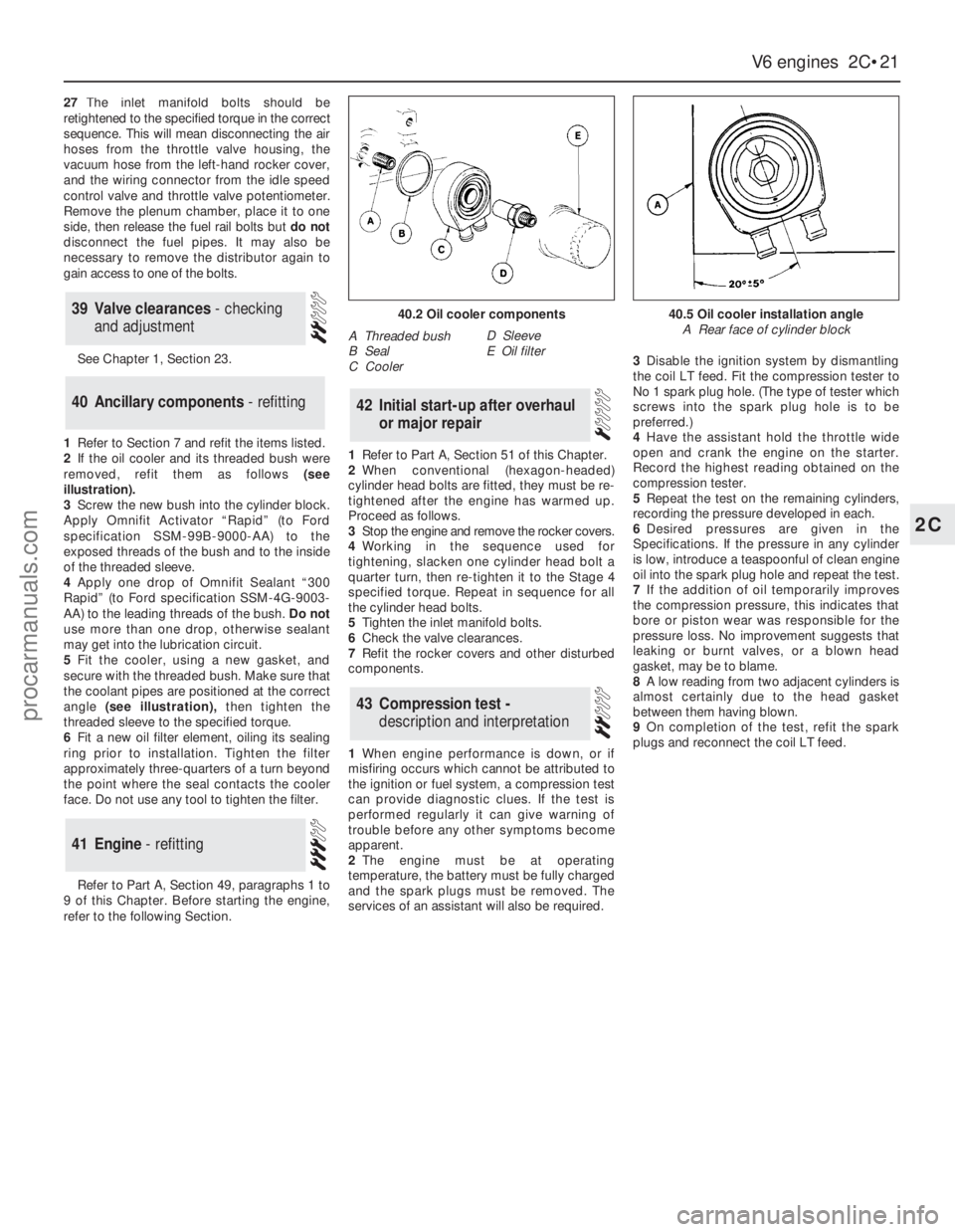
removed, refit them as follows (see
illustration).
3Screw the new bush into the cylinder block.
Apply Omnifit Activator “Rapid” (to Ford
specification SSM-99B-9000-AA) to the
exposed threads of the bush and to the inside
of the threaded sleeve.
4Apply one drop of Omnifit Sealant “300
Rapid” (to Ford specification SSM-4G-9003-
AA) to the leading threads of the bush.Do not
use more than one drop, otherwise sealant
may get into the lubrication circuit.
5Fit the cooler, using a new gasket, and
secure with the threaded bush. Make sure that
the coolant pipes are positioned at the correct
angle (see illustration),then tighten the
threaded sleeve to the specified torque.
6Fit a new oil filter element, oiling its sealing
ring prior to installation. Tighten the filter
approximately three-quarters of a turn beyond
the point where the seal contacts the cooler
face. Do not use any tool to tighten the filter.
Refer to Part A, Section 49, paragraphs 1 to
9 of this Chapter. Before starting the engine,
refer to the following Section.1Refer to Part A, Section 51 of this Chapter.
2When conventional (hexagon-headed)
cylinder head bolts are fitted, they must be re-
tightened after the engine has warmed up.
Proceed as follows.
3Stop the engine and remove the rocker covers.
4Working in the sequence used for
tightening, slacken one cylinder head bolt a
quarter turn, then re-tighten it to the Stage 4
specified torque. Repeat in sequence for all
the cylinder head bolts.
5Tighten the inlet manifold bolts.
6Check the valve clearances.
7Refit the rocker covers and other disturbed
components.
1When engine performance is down, or if
misfiring occurs which cannot be attributed to
the ignition or fuel system, a compression test
can provide diagnostic clues. If the test is
performed regularly it can give warning of
trouble before any other symptoms become
apparent.
2The engine must be at operating
temperature, the battery must be fully charged
and the spark plugs must be removed. The
services of an assistant will also be required.3Disable the ignition system by dismantling
the coil LT feed. Fit the compression tester to
No 1 spark plug hole. (The type of tester which
screws into the spark plug hole is to be
preferred.)
4Have the assistant hold the throttle wide
open and crank the engine on the starter.
Record the highest reading obtained on the
compression tester.
5Repeat the test on the remaining cylinders,
recording the pressure developed in each.
6Desired pressures are given in the
Specifications. If the pressure in any cylinder
is low, introduce a teaspoonful of clean engine
oil into the spark plug hole and repeat the test.
7If the addition of oil temporarily improves
the compression pressure, this indicates that
bore or piston wear was responsible for the
pressure loss. No improvement suggests that
leaking or burnt valves, or a blown head
gasket, may be to blame.
8A low reading from two adjacent cylinders is
almost certainly due to the head gasket
between them having blown.
9On completion of the test, refit the spark
plugs and reconnect the coil LT feed.
43Compression test -
description and interpretation
42Initial start-up after overhaul
or major repair
41Engine - refitting
40Ancillary components - refitting
39Valve clearances - checking
and adjustment
V6 engines 2C•21
2C
40.2 Oil cooler components
A Threaded bush
B Seal
C CoolerD Sleeve
E Oil filter
40.5 Oil cooler installation angle
A Rear face of cylinder block
procarmanuals.com
Page 94 of 255
Chapter 4
Fuel and exhaust systems
Air cleaner and element - removal and refitting . . . . . . . . . . . . . . . . .2
Air cleaner temperature control - description and testing . . . . . . . . .3
Carbon canister - removal and refitting . . . . . . . . . . . . . . . . . . . . . .44
Carbon canister purge solenoid - removal and refitting . . . . . . . . . .45
Exhaust gas oxygen (HEGO) sensor - removal and refitting . . . . . .43
Exhaust manifold(s) - removal and refitting . . . . . . . . . . . . . . . . . . .41
Exhaust system - inspection, repair and renewal . . . . . . . . . . . . . .42
Fuel cut-off inertia switch - removal and refitting . . . . . . . . . . . . . . . .7
Fuel filter - renewal . . . . . . . . . . . . . . . . . . . . . . . . . . . . . . . . . . . . . .30
Fuel gauge sender unit - removal and refitting . . . . . . . . . . . . . . . . . .6
Fuel-injection system - depressurisation . . . . . . . . . . . . . . . . . . . . .28
Fuel-injection system - idle speed and mixture adjustments . . . . . .31
Fuel-injection system relays - location . . . . . . . . . . . . . . . . . . . . . . .29
Fuel-injectors - removal and refitting . . . . . . . . . . . . . . . . . . . . . . . .36
Fuel pressure regulator - removal and refitting . . . . . . . . . . . . . . . .37
Fuel pump - testing, removal and refitting . . . . . . . . . . . . . . . . . . . . .4
Fuel rail temperature switch - removal and refitting . . . . . . . . . . . . .39
Fuel tank - removal and refitting . . . . . . . . . . . . . . . . . . . . . . . . . . . . .5
General information and precautions . . . . . . . . . . . . . . . . . . . . . . . . .1
Idle speed control valve - removal and refitting . . . . . . . . . . . . . . . .34
Inlet manifold - removal and refitting . . . . . . . . . . . . . . . . . . . . . . . .40
Mixture adjustment potentiometer - removal and refitting . . . . . . . .38
Pierburg 2V carburettor - dismantling and reassembly . . . . . . . . . .13
Pierburg 2V carburettor - fast idle adjustment . . . . . . . . . . . . . . . . .14
Pierburg 2V carburettor - idle speed and mixture adjustments . . . .11
Pierburg 2V carburettor - removal and refitting . . . . . . . . . . . . . . . .12Throttle body - removal and refitting . . . . . . . . . . . . . . . . . . . . . . . .33
Throttle cable - removal and refitting . . . . . . . . . . . . . . . . . . . . . . . . .9
Throttle pedal - removal and refitting . . . . . . . . . . . . . . . . . . . . . . . . .8
Throttle position sensor - removal and refitting . . . . . . . . . . . . . . . .32
Unleaded fuel - general . . . . . . . . . . . . . . . . . . . . . . . . . . . . . . . . . .46
Vane airflow meter(s) - removal and refitting . . . . . . . . . . . . . . . . . .35
Vapour separator - removal and refitting . . . . . . . . . . . . . . . . . . . . .10
Weber 2V carburettor - automatic choke adjustment . . . . . . . . . . .18
Weber 2V carburettor - dismantling and reassembly . . . . . . . . . . . .17
Weber 2V carburettor - idle speed and mixture adjustments . . . . .15
Weber 2V carburettor - removal and refitting . . . . . . . . . . . . . . . . . .16
Weber 2V TLD carburettor - automatic choke unit removal,
refitting and adjustment . . . . . . . . . . . . . . . . . . . . . . . . . . . . . . . .26
Weber 2V TLD carburettor - accelerator pump diapragm renewal .25
Weber 2V TLD carburettor - idle speed and mixture adjustments . .19
Weber 2V TLD carburettor - low vacuum enrichment
diaphragm renewal . . . . . . . . . . . . . . . . . . . . . . . . . . . . . . . . . . . .24
Weber 2V TLD carburettor - needle valve and float removal,
refitting and adjustment . . . . . . . . . . . . . . . . . . . . . . . . . . . . . . . .21
Weber 2V TLD carburettor - power valve diaphragm renewal . . . . .23
Weber 2V TLD carburettor - removal and refitting . . . . . . . . . . . . .20
Weber 2V TLD carburettor - secondary throttle valve vacuum
diaphragm renewal . . . . . . . . . . . . . . . . . . . . . . . . . . . . . . . . . . . .22
Weber 2V TLD carburettor - throttle kicker removal, refitting
and adjustment . . . . . . . . . . . . . . . . . . . . . . . . . . . . . . . . . . . . . . .27
General
System type:
1.8 litre . . . . . . . . . . . . . . . . . . . . . . . . . . . . . . . . . . . . . . . . . . . . . . . . Twin choke Pierburg carburettor
2.0 litre carburettor:
SOHC . . . . . . . . . . . . . . . . . . . . . . . . . . . . . . . . . . . . . . . . . . . . . . . Twin choke Weber 2V carburettor
DOHC . . . . . . . . . . . . . . . . . . . . . . . . . . . . . . . . . . . . . . . . . . . . . . . Twin choke Weber 2V TLD carburettor
All models with fuel injection . . . . . . . . . . . . . . . . . . . . . . . . . . . . . . . . Multi-point fuel-injection system controlled by EEC IV engine
management system
Fuel tank capacity . . . . . . . . . . . . . . . . . . . . . . . . . . . . . . . . . . . . . . . . . . 70 litres (15.4 gallons) approx
Fuel grade*:
Leaded . . . . . . . . . . . . . . . . . . . . . . . . . . . . . . . . . . . . . . . . . . . . . . . . 97 octane RON (UK 4-star)
Unleaded . . . . . . . . . . . . . . . . . . . . . . . . . . . . . . . . . . . . . . . . . . . . . . . 95 octane RON (Premium)
* Models fitted with a catalytic converter must be operated on unleaded fuel at all times. Do notuse leaded fuel as the catalyst will be destroyed.
Idle speed:
1.8 litre . . . . . . . . . . . . . . . . . . . . . . . . . . . . . . . . . . . . . . . . . . . . . . . . 800 ± 20 rpm
2.0 litre carburettor:
SOHC* . . . . . . . . . . . . . . . . . . . . . . . . . . . . . . . . . . . . . . . . . . . . . . . 800 or 875 rpm
DOHC:
Manual gearbox* . . . . . . . . . . . . . . . . . . . . . . . . . . . . . . . . . . . . . 850 ± 25 rpm
Automatic transmission* . . . . . . . . . . . . . . . . . . . . . . . . . . . . . . . 875 ± 25 rpm
2.0 litre fuel-injection:
SOHC* . . . . . . . . . . . . . . . . . . . . . . . . . . . . . . . . . . . . . . . . . . . . . . . 800 or 875 rpm
DOHC* . . . . . . . . . . . . . . . . . . . . . . . . . . . . . . . . . . . . . . . . . . . . . . . 875 ± 50 rpm
4•1
Easy,suitable for
novice with little
experienceFairly easy,suitable
for beginner with
some experienceFairly difficult,
suitable for competent
DIY mechanicDifficult,suitable for
experienced DIY
mechanicVery difficult,
suitable for expert
DIY or professional
Degrees of difficulty
Specifications Contents
4
procarmanuals.com