Page 65 of 168
Fuel pump
~
0580464 ...
135793
Tank pump
70019401960 Specifications
Section
2 B 200, B 230 Engines
Bosch PIN. . . . . . . . . . . . . . . . . . . . . . . . . . . . . . . .. . .. 039
Volvo PIN. . . . . . . . . . . . . . . . . . . . . . . . . . . . . .. 1 389449-8
Pump capacity at
300 kPa (42 psi) line pressure.
+20°C
12 V .............................. .
'
11 V ............................. ..
10 V .............................. . 130
litres/hour
108 litres/hour 65 litreslhour
Current consumption at
300 kPa (42 psi) line pressure.
+20°C & 12 V .......................... max 6.5 A
Current consumption. . . . . . . . . . . . . . . . . . . . . . . . . .
3-4 A
63
Page 66 of 168

700/940/960 Specifications
Section 2' 8200,8230 Engines
Group 25 Intake and exhaust systems
Turbo engines
'-198~
Engine type .... ; ......... . , ............ .. .............
Charg~ pressure, at full load and ................... r/min
checking
.. ................... kPa (psi)
setting. . . . . . . . . . . . . . . . . . . . .
.. kPa (psi)
Charge air overpressure, switch opens at ....... kPa
(psi)
Charge air pressure, switch closes at ........... kPa (psi)
Tightening torques
4) 18 Nm (13 ft IW)
/
1) Apply sealer PIN 1 161 053-2. 2) Use new nuts
3) Use sealer PIN 1161 035-9.
8200/230 ET
3500
45-53 (6.4-7.5)
50 (7.1)
65-75 (9.2-10.7)
15-25 (2. 1-3.6)
3)
4) Use new boils. If absolutely necessary, old boils can be reused if they
are smeared with sealer PIN 1161053-2.
Mounting bolts, turbocharger -exhaust manifold
• Measure length of bolt. Bolts can be reused if shorter
than
89 mm (3.5 in)
• Apply assembly paste PIN 1 161 078-9 to mating sur-<=;==;=""-~
faces and threads
• Fit new locking plates
•
Tighten bolts in three stages according to below
64
Stage I = 1 Nm (0.7 ft Ib)
II = 45 Nm (33 ft Ib)
III = 45° in one motion without stopping
89mm
135780
~Nm
s::L).Nm
8230FT
3000
46-54 (6.5-7.7)
48-54 (6.8-7.7)
85-95 (12 .1-13.5)
-
136772
Page 67 of 168
Turbo engines
1990-
700194 01960 Specifications
Section
2 B 200, B 230 E ngines
Engine type ......... ................................ ..... .. .... B23 0FT/GT
Charge p ressure, at full load and ......... ' .................. r/min 3000
checking ............................. kPa (psi)
48-54 (6.8-7.7)
setting ...... .................... ' ...... kPa (psi) 51 (7.3)
Pressure sensor, leak test kPa (psi)
Relief valve , fully open at pressure difference kPa (psi)
Tightening torques
J.
'1:C@1 ,
147 943
T ightening sequ ence (Turbocharger -exhaust manifold)
60-70 (8.5-10.0)
22 (3.1)
Turbocharger -exhaust manifold ' ...... 3 0 N m (22 ft Ib)
Use special tool 5411 (at 90° angle to torque wrench)
T urbocharger
-exhaust pipe ' .......... 30 Nm (22 ft Ib)
• Use sealer PIN 1161035-9 .
65
Page 68 of 168

70019401960 Specifications
Section 2 B 200, B 230 Engines
General
Expansion tank
Group 26 Cooling system
128187
Coolant -composition -guarantee
Since aluminium is used in the engines, active corrosion
protection is necessary
in the coolant to help prevent corro
sion damage.
Use genuine
Volvo coolant, type C (blue-green), diluted
with clean water in proportions of 50/50. This mixture helps
to prevent corrosion and frost damage .
• Never top-up the cooling system with water alone. Use
genuine
Volvo coolant diluted with clean water in propor
tions of 50/50 .
•
The coolant should be changed every 25,000 miles
(40,000
km) since the corrosion -protective additives in
the coolant lose their effect in time.
• Clean cooling system with solvent (P/N 1161328-8
prior to
filling new coolant.
Capacity, B 200/230. . . . . . . . . . . . . . . . . . approx 8.5 litres
US qts 9.0
B 204/234. . . . . . . . . . . . . . . . .. approx 9.5 litres
US qts 10.0
Pressure valve
in filler cap opens at;· . kPa psi
11
14
21
1.0
overpressure, early type .. . . . . . . . . . . . . . . . . . . . . . . . . . . . . . . . . . . 75
late type without turbo . . . . . . . . . . . . . . . . . . . . . . . . . 100
with turbo and B 204/234. . . . . . . . . . . . . . . 150
underpressure . . . . . . . . . . . . . . . . . . . . . . . . . . . . . . . . . . . . . . . . . . . . . 7 .0
Thermostat
Marking ............................ ........................ .
Starts to open
at ......... .............. ..................... .
Fully open at ............................................... .
66
Type 1
87
86-88 °C
(187-190 °
F)
9rC
(20rF)
Type 2
92
91-93°C
( 196-199 °F)
102°C
(216 °
F)
Page 69 of 168

70019401960 Specifications
Section
2 B 200, B 230 Engines
Group 28 Ignition system
Type. . . . . . . . . . . . . . . . . . . . . . . . . . . . . . . . . . . . . . . . . . . . . . . . . . . . . . . . Breakerless
Firing order. . . . . . . . . . . . . . . . . . . . . . . . . . . . . . . . . . . . . . . . . . . . . . . . . . 1-3-4-2
E
ngine Ignition
type timing
b.t.d.c.
B200K 15°
B200F .12°
B200E 12 °
B200ET 14°
B204E 15°
B204FT/GT 10°
B230A* 7°
B230K 15°
, Vacuum regulator disconnected . '* Japan -1988: 15 rls (900 rpm).
Speed rls
(rpm)
12.5
(750)
12.1- 13.8 (725-825)
14.2 -15.8
(850-950)
14.7-15.3 (880-920)
14.2-15.8 (850-950)
13.0-13.7 (780-820)
11.7-13.3 (700-800)
13.3 (800)
''* Ignition system Rex, USNCanada : 10°.
Ignition coil
Engine Ignition
type timing
b.t.d.c.
B230E 12°
B230ET 10°
B230F -1988 12 °
1989-12°***
B230FB 12 °
B230fT/GT 12°
B234F/G 15°
B200E,B200K,B230E
B 230 F, B 230 FB, B 230 K,
Speed rls
(rpm)
14.2-15.8
(850-950)
14.7 -15.3 (880-920)
12.2 -12.8 (730-770)* '
12.1-13.8 (725-825)
12.9 (775)
12.2 -12.8
(730-770)* *
13.3-15.0 (800-900)
B200ET,
B230ET B230F
131 7~1 B230A B 230 FT, B 204 E, B 204 FT/GT, Rex
B234 FIG
Resistance of primary coil (terminals
1 and 15) .................................... . 0.6-0.90 0.6-0.80 0.50 0.50
Resistance of secondary coil
(terminal
1 to HT terminal ...................... . 6.5-8. 5 kO 6 .9-8.5 kO 6 .0 kO 5 .0 kO
Knock sensor
II 146804
Tightening torque, type I . . . . . . . . . . . . . . . . . . . . . . . . . . . . . . . . . . . . . . 11 Nm (8 ft Ib)
type 11......... ............................. 20 Nm (14.5 It Ib)
67
I
I
I
til' ·ut til, til lit ·
t''''' '111 lit
Page 70 of 168

I
I
I
70019401960 Specifications
Section 2 B 200, B 230 Engines
Spark plugs, g low plugs
I~~n
~ 143983
E ngin e type Designation Type I Type II
P
IN Se t number PIN Set number
B 200 K, B 200 ET, B 200 F,
B 230 A, B 230 K -1986, B 230 ET WR7DC " 1 306605-5 273597-5
1 367528-5 270 746-1
B 200 E, B 204 ElFT/GT, B 230 K
1987-, B
230 E, B 234 FIG WR6DC** 1 306604-8 273596-7 1 367529-3 270 747-9
B
230 F, B 230 FB, B 230 FT/GT WR7DC 1 346 541-4 271 409-5
1 367528-5 270 746-1
B 230 FT Europe WR6DC 1
367015-3 271 415-2
1 367529-3 270 747-9
• Type II spark plugs are standard on B 200/230 -1988-but can also be used on earlier engines (provided HT leads and ground lead are replaced at same time) . .. Up to 1987 W7DC (W6DC, type I).
Electrode gap .............................................. . 0.7-0.8 mm (0.0276-0.315 in)
25 Nm (18 ft Ib) Tightening torque, (unoiled plugs) ............................. .
Distributor
E ngine type Ignition system
B200E, B230K EZ-K
B
230 E, B 230 F -1988, B 230 FT
-1989
EZ- K
B200K Renix
B200F EZ 116 K
B
230 F 1989-, B 230 FB,
B 230 FT/GT 1990 EZ 116 K (Rex ')
B 200 ET , B 230 ET Motronic
B230A TZ-28 H
B
204 E/FT/GT, B 234 FIG EZ 116 K
'USA only
Centr ifugal governor
Advance, total degrees (distributor) . . . . . . . . . . .. 12,5± 1
Advance begins at distrib. rev/sees ............ 7.5-10.5
distrib . rev/min. . . . . . . . . . . .. (450-630) Data : 5° at distrib . rev/sees . . . . . . . . . . . . . . . . .. 16 .5-20.5 (distrib. rev/min) . . . . . . . . . . . . . . . . .. (1000-1250) 10° at distrib . rev/sees . . . . . . . . . . . . . . . . .. 25-29 (distrib . rev/min) .................. (1500-1750)
Advance max at distrib. rev/sees .............. 31.7
(distrib. rev/min) . . . . . . . . . . . . .. (1900)
Vacuum governor
Control direction ............... .. ........... . Control, total degrees (distributor) .......... .. . Control commences at mm Hg ............... .
Data : 5° at mm Hg . .. ....................... .
max control at mm Hg ........ .... ..... .
68
Positive
7.5±1 105-145
165-210
240
Distributor
Volvo PIN Bosch No
1
336087 0237502001
1 336087 0237502001
1 336 132 0237502002
1 336132 0237502002
1 336 132 0237502002
1 336 132 0237502002
1 336690 0237024013
1 367197 0237502003
Ignition advance, B 230 A
~.
rrr~,o , 2p , 3,0 , 4 ,0 , 5,0 , 6,0~;;. + l ' 0 500 1000 1500 2000 2500 3000 3500 4000 rl min
40.20"~mm Wmfmm ~mmfffi=mmm
o· Ii'
-10' -ft '0237 0 24 013
10 20 30 iii 100 200 40 50 60 kpa 3bo i 460 j mm iHg
13 6780
i
Page 71 of 168

70019401960 Specifications
Section
2 B 28 Engine
Section 2 B 28 Engine
Group 20 General . . . . . . . . . . . . . . . . . . . . . . . . . . . . . .. 69
Group 21 Engine................................ 70
Group 22 Lubricating system ...................... 74
Group 23 Fuel system ............ . . . . . . . . . . . . . .. 75
Group 25
Intake and exhaust systems ............. 82
Group 26 Cooling system ......................... 83
Group 28
Ignition system. . . . . . . . . . . . . . . . . . . . . . . .. 84
129756
Group 20 General
Performance, compression ratios, octane requirements
E ngine Compression Octane
type ratio r
eq
uirement
B28A 8.8:1 91-93
B28E 9 .5 :1 981
)
B28F 8.8 :1 912
)
1) Australia 97-98 octane 2) According to research method (RON). Unleaded gasoline
According to formula (R+M/2) = 87 octane 3) ft. lb. 4) Horse power
Other general data
kWat
rl s
96/88
115/95
100/92
Number of cylinders ......................................... .
Bore
.............. ......................................... .
Stroke ................ " ................................... .
Displacement ............................................... .
Firing order
................................................. .
Compression
(normal rating)l) ........................... ..... .
Weight, approx
................ ............................. .
I) With hot engine, throttle wide open and starter motor cranking at 4.2-5.0 rls (250-300 r/min).
Output
hp at
r/min
130/5250
156/5700
136/5500
134
4)/5500
6
91 mm (3.582 in)
73 mm (2.874 in)
2 .849 dm3 (Iitres)
1-6-3-5 -2-4
Nm at
rl s
212150
235/50
215/46
0.8-1 .1 MPa (114-156 psi)
150 kg (330 Ib)
/ ......
l.t
~ '
129750
Max torque
kpm at
r/min
21.6/3000
24.0/3000
21. 9/2750
1593)/2. 700
69
"' '" ill
,' ....
N,'
'" III
Page 72 of 168
 per
100 mm (4 in) length.
Note: Do not level a warped cyli")
70019401960 Specifications
Section'-2" B 28 Engine
Group 21 Engine block
Cylinder head
Max warp:
Maxium warp is
0.05 mm (0.002 in) per
100 mm (4 in) length.
Note: Do not level a warped cylinder head,
replace it!
Cylinder liners
[
Bore, liners marked 1 (A-marked piston) ....................... .
2 (B-marked piston) ....................... .
3 (C-marked piston) ...................... .
Liner height above
block face:
checking (runing engine,
old shims) ....................... .. .
adjusting (new shims)
..................................... .
Pistons
Max weight difference between pistons in same engine .......... .
Piston
float ................................................. .
Piston diameter A-marked pistons
......... .
B-marked pistons
......... .
C-marked pistons
........ .
]
91.00-91.01 mm
91.01-91.02 mm
91.02-91.03 mm
0.14--0.23 mm
0.16-0.23 mm
6 grams
0.020-0.040 mm
90.970-90.980 mm
90.980-90.990 mm
90.990-91.000 mm
3.5826-3.5830 in
3.5830-3.5835 in
5.5835-5.5838 in
0.0055-0.0091 in
0.0063-0.0091 in
0.0007-0. 0015 in
3.5814-:3.5818 in
3.5818-3.5822 in
3.5822-3.5826 in
((0)) t
'" ~L-f
Piston diameter is measured at right-angles to gudgeon pin bore, S mm from bottom edge.
135676
Piston rings
/,
I 111111111 ~III
'--J 115085
Side clearance (measured with ring on piston) ............... mm
in
Ring gap when checked in 91 mm (3.5826 in) cylinder,
Ring gap measured 15 mm
(0.6 in) from lower edge of
cylinder
U 129520 pper
compression
ring
0.045-0.074
0.0017-0.0029
Lower Oil ring
compression
ring
0.025-0.054 0.009--0.233
0.0009--0.0212 0.0003-0.0091
(see fig) ................................................. mm 0.40-0.60 0.40-0.60 0.40-1.45
in 0.0157-0.0236 0.0157-0.0236 0.0157-0.0570 Gudgeon (piston) pins
Clearance in connecting rod. . . . . . . . . . . . . . . . . . . . . . . . . . . . . . . . . . . 0.020-0.041 mm
piston. . . . . . . . . . . . . . . . . . . . . . . . . . . . . . . . . . . . . . . . . . .
0.010-0.016 mm
70 0.0007-0.0016
in
0.0003-0.0006 in
 1
1 2
2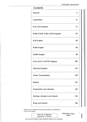 3
3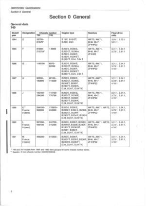 4
4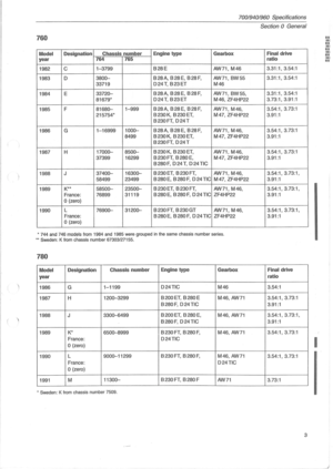 5
5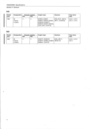 6
6 7
7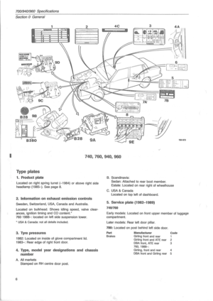 8
8 9
9 10
10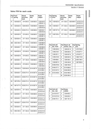 11
11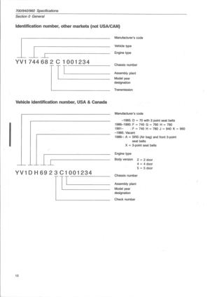 12
12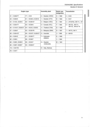 13
13 14
14 15
15 16
16 17
17 18
18 19
19 20
20 21
21 22
22 23
23 24
24 25
25 26
26 27
27 28
28 29
29 30
30 31
31 32
32 33
33 34
34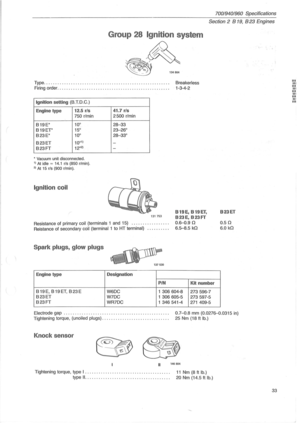 35
35 36
36 37
37 38
38 39
39 40
40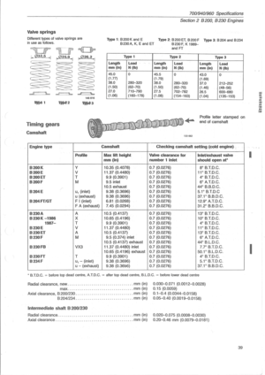 41
41 42
42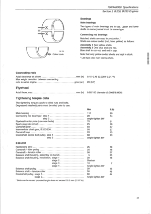 43
43 44
44 45
45 46
46 47
47 48
48 49
49 50
50 51
51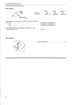 52
52 53
53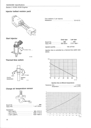 54
54 55
55 56
56 57
57 58
58 59
59 60
60 61
61 62
62 63
63 64
64 65
65 66
66 67
67 68
68 69
69 70
70 71
71 72
72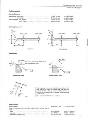 73
73 74
74 75
75 76
76 77
77 78
78 79
79 80
80 81
81 82
82 83
83 84
84 85
85 86
86 87
87 88
88 89
89 90
90 91
91 92
92 93
93 94
94 95
95 96
96 97
97 98
98 99
99 100
100 101
101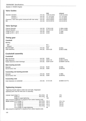 102
102 103
103 104
104 105
105 106
106 107
107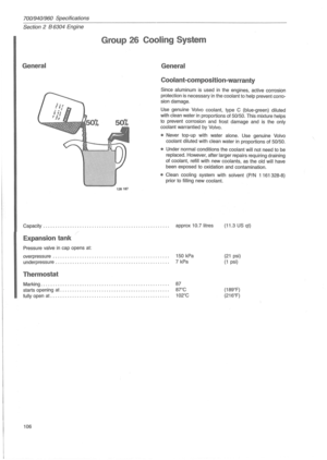 108
108 109
109 110
110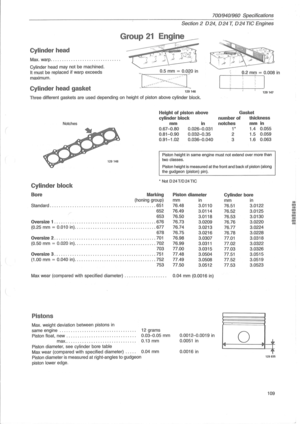 111
111 112
112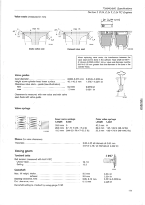 113
113 114
114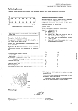 115
115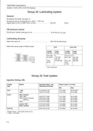 116
116 117
117 118
118 119
119 120
120 121
121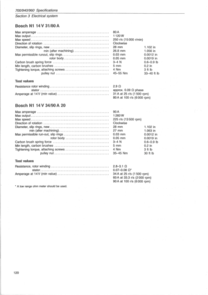 122
122 123
123 124
124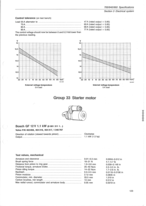 125
125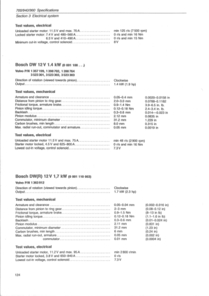 126
126 127
127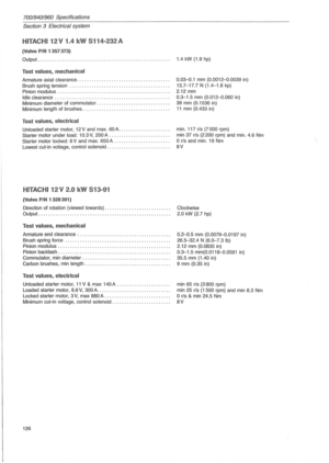 128
128 129
129 130
130 131
131 132
132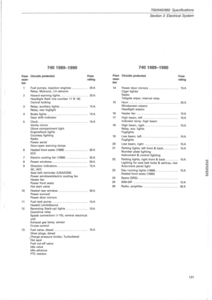 133
133 134
134 135
135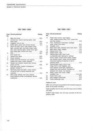 136
136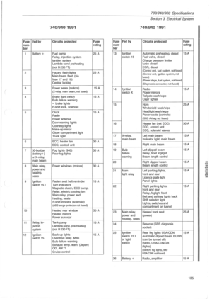 137
137 138
138 139
139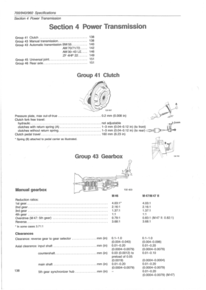 140
140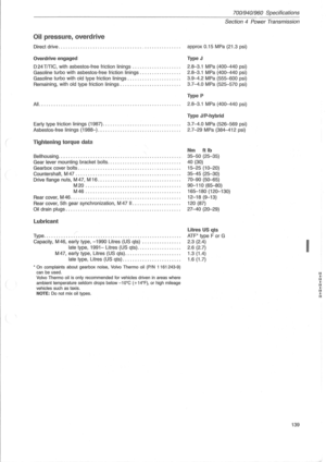 141
141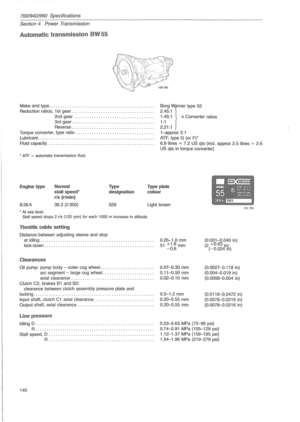 142
142 143
143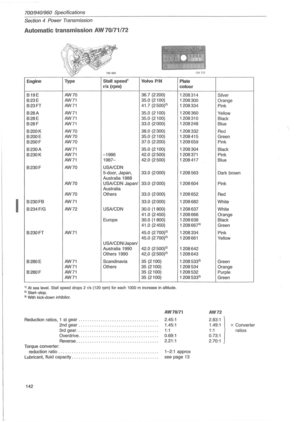 144
144 145
145 146
146 147
147 148
148 149
149 150
150 151
151 152
152 153
153 154
154 155
155 156
156 157
157 158
158 159
159 160
160 161
161 162
162 163
163 164
164 165
165 166
166 167
167
