1982 VOLVO 940 oil pressure
[x] Cancel search: oil pressurePage 19 of 168
(
70019401960 Specifications
Section
2 B 19, B 23 Engines
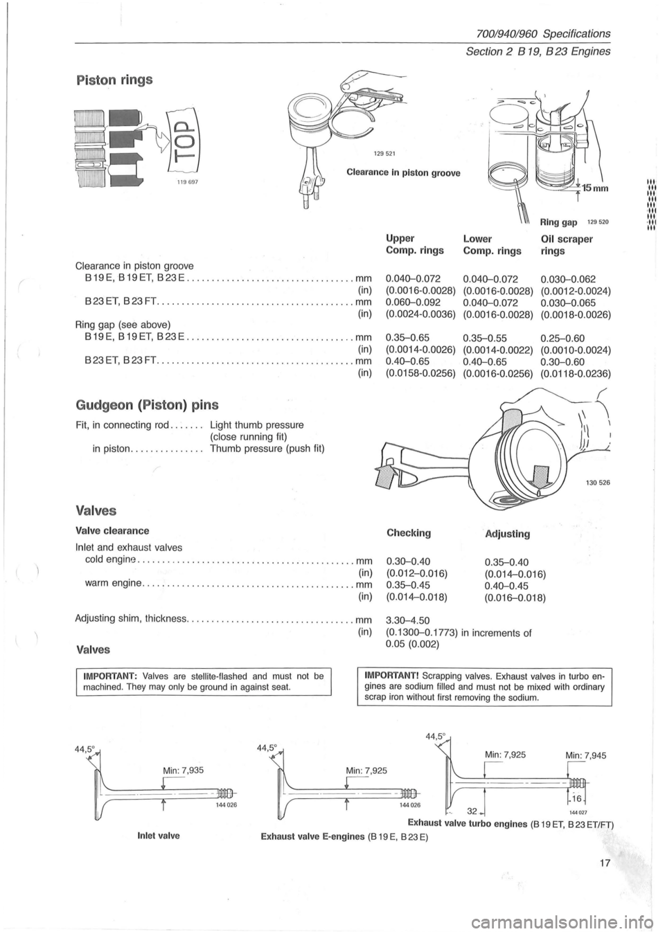
P iston rings
129521
Clearance In piston groove
Clearance in piston groove
819 E, 819 ET, 823 E .................................. mm
(in)
823ET, 823FT .............. .......................... mm
(in)
Ring gap (see above)
819E, 819ET, 823E .................................. mm
(in)
823ET, 823FT ................ .......... .............. mm
Gudgeon (Piston ) pins
Fit, in connecting rod. . . . . .. Light thumb pressure
(close running fit)
in piston. . . . . . . . . . . . . .. Thumb pressure (push fit)
Valves
Valve clearance
Inlet
and exhaust valves
(in)
cold engine ............................................ mm
(in) warm engine ........................................... mm
(in)
Adjusting shim, thickness .................................. mm
(in)
Valves
Upper
Camp.
rings
0.040-0 .072
(0. 0016-0.0028)
0.060-0 .092
(0.0024-0.0036)
0 .35-0.65
(0.0014 -0 .0026)
0.40-0 .
65
(0.0158-0.0256)
Checking
0.30-0.40
(0.012-0.Q16)
0.35-0.45
(0.014-0.018)
3 .
30-4.50
Ring gap 129 520
Lower Oil scraper
Camp.
rings rings
0.040-0.072 0.030-0.062
(0.0016 -0 .0028) (0.0012 -0.0024)
0.040-0.072 0.030-0.065
(0.0016-0.0028) (0.0018-0.0026)
0.35-0.55 0.25-0.60
(0.0014-0.0022) (0.0010-0.0024)
0.40-0.65 0.30-0.60
(0.0016-0.0256) (0.0118-0.0236)
'Adjusting
0.35-0.40
(0. 014-0 .016)
0.40-0.45
(0. 016-0.018)
(0.1300-0 .1773)
in increments of
0.05 (0.002)
IMPORTANT: Valves are stellite-flashed and must not be machined . They may only be ground in against seat. IMPORTANT! Scrapping valves. Exhaust valves in turbo engines are sodium filled and must not be mixed with ordinary
scrap iron without first removing the sodium.
Min: 7,935
Inlet valve
44,5°
44,5 °
Min: 7,945
144027
Exhaust valve turbo engines (8 19 ET, 823 ET/FT)
Exhaust valve E-engines (8 19 E, 823 E)
17
III' III III
III
III ,111 III ·111 III
Page 22 of 168
70019401960 Specifications
Section 2 B
19, B 23 Engines
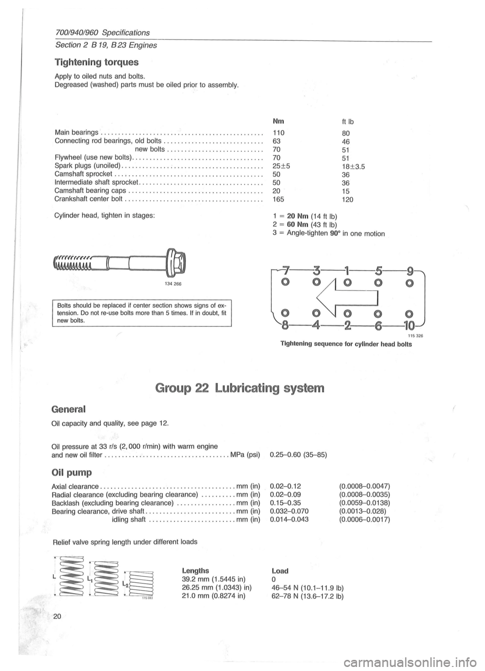
Tightening torques
Apply to oiled nuts and bolts.
Oegreased (washed) parts must be oiled prior to assembly.
Main bearings ....................... ' ....................... .
Connecting rod bearings,
old bolts ............................ .
new
bolts ......... .................. .
Flywheel (use new bolts) ..................................... .
Spark
plugs (unoiled) .............. ; ......................... .
Camshaft sprocket
............... ........................... .
Intermediate shaft sprocket ................................. .. .
Camshaft bearing caps .
............................ ......... .
Crankshaft center
bolt ....................................... .
Cylinder head , tighten in stages:
134266
Bolts should be replaced if center section shows signs of extension. Do not re-use bolts more than 5 times . If in doubt, fit
new bolts.
Nm
110
63
70
70
25±5
50
50 20
165
1 = 20 Nm (14 ft Ib)
2 = 60 Nm (43 ft Ib)
ft Ib
80
46
51
51
18±3.5
36
36 15
120
3 = Angle-tighten 900 in one motion
'7--3---
o 0
000
8-4-2-
--9
o
115326
Tightening sequence for cylinder head bolts
Group 22 Lubricating system
General
Oil capacity and quality, see page 12.
Oil pressure at 33 rls (2,000 r/min) with warm engine
and new
oil filter ...... .............................. MPa (psi) 0.25-0.60 (35-85)
Oil pump
Axial clearance .................. ..................... mm (in)
Radial clearance (excluding bearing clearance) .......... mm (in)
Backlash (excluding bearing clearance) ................. mm (in)
Bearing clearance, drive shaft
.......................... mm (in)
idling shaft ..... ........... .......... mm (in)
Relief valve spring length under different loads
~~~ 115083
20
Lengths
39.2 mm (1.5445 in)
26.25 mm (1.0343) in)
21.0 mm (0.8274 in)
0.02-0.12
0.02-0.09
0.15-0.35
0.032-0.070
0.014-0.043
Load
o
(0.0008-0 .0047)
(0.0008-0.0035)
(0.0059-0.0138)
(0.0013-0. 028)
(0.0006-0.0017)
46-54 N (10.1-11.9 Ib)
62 -78 N (13.6-17.2 Ib)
(
Page 38 of 168
70019401960 Specifications
Section 2 B 200, B 230 Engines
Other General Data
Number of cylinders ......................................... .
80re .................................................... mm
Stroke .................................................. mm
Displacement. ..................................... dm3 (litres)
Firing order ................................................. .
Compression pressure
.............................. MPa (psi)
Max deviation between
cylinders ................... MPa (psi)
Weight
.................... ..................... .......... kg
(Ib)
B200
B204
4 88.9
80
B230
B234
4
96
80
2.32 1-3-4-2
0.9 (128)
0.2 (28)
140-150
(308-330)
with turbocharger .................................... kg
1.99
1-3-4-2
0.9 (128)
0.2 (28)
140-150
(308-330)
165 (363) 160-165 (352-363)
1) With hot engine throttle wide open and starter motor cranking at 4.2-5.0 rls (250-300 r/min).
Cylinder block
Bore
Group 21 Engine block
Standard, C ............................................. mm
(in)
o .... ............ ..................... ........ mm
(in)
E
.... ......................................... mm
(in)
G .
............................................ mm
(in)
Oversize
1 .......... . ........... ........................ mm
(in)
2 ............ -.................................. mm
(in)
B200
88.90-88.91
(3.5027-3.5031 )
88.91-88.92
(3.5031-3.5034)
88.92-88.93
(3.5034-3 .5038)
88.94-88.95
(3.5042-3.5047)
89.29-89.30
(3.5180-3.5184)
89 .
67-89.68
(3.5303)
Rebore if wear exceeds 0.1 mm (0.004 in) and oil consumption is very high.
Pistons
Piston diamete r (A)
Standard (C) ............................................. mm
(D) ............................................. mm
(E)
....................................... ...... mm
(G) ........ .................................... mm
Oversize 1 .............................................. mm
2 ................................ ······· ·······mm
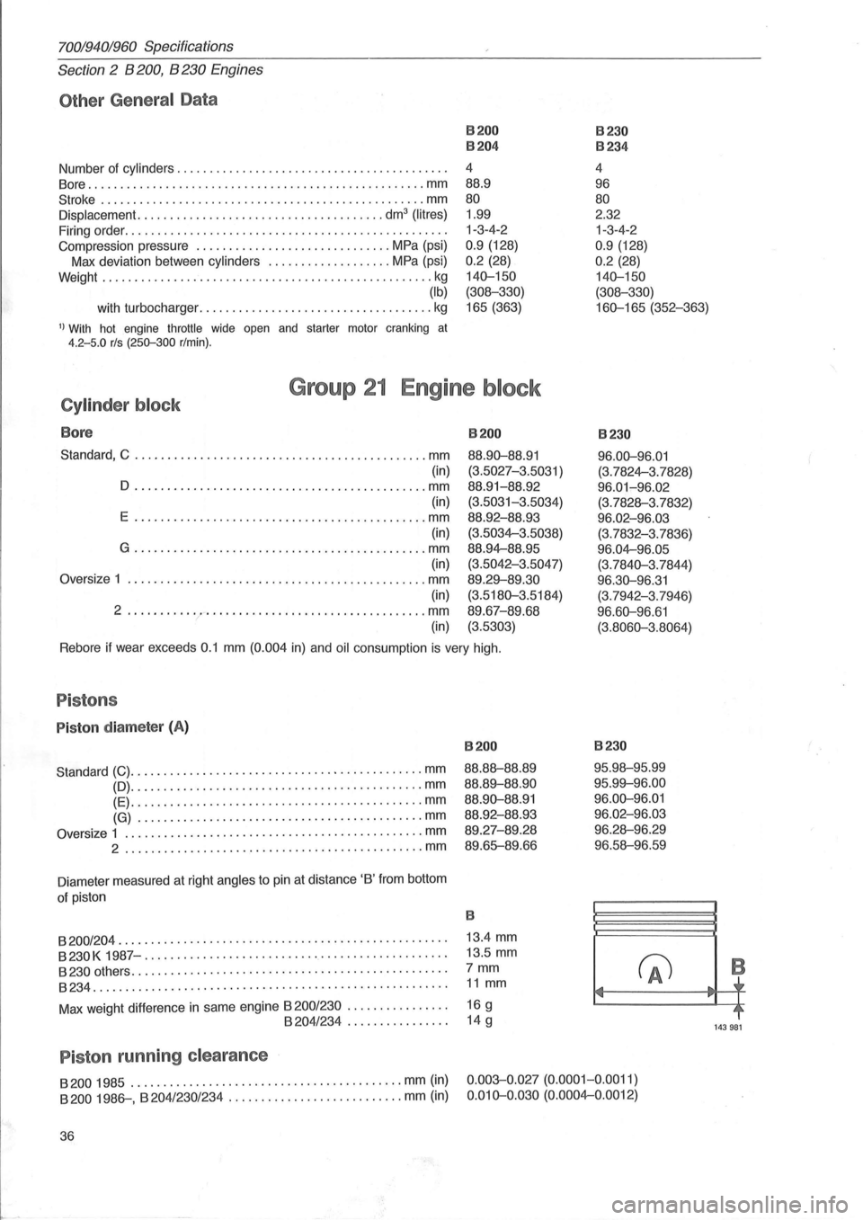
Diameter measured at right angles to pin at distance 'B' from bottom
of piston
B200
88.88-88.89
88.89-88.90
88.90-88.91
88.92-88.93
89.27-89.28
89.65--89 .66
B
8200/204 . . . . . . . . . . . . . . . . . . . . . . . . . . . . . . . . . . . . . . . . . . . . . . . . . . . 13.4 mm
B230K 1987-..... ...... ................. ................... 13 .5 mm
8230 others. . . . . . . . . . . . . . . . . . . . . . . . . . . . . . . . . . . . . . . . . . . . . . . . . 7 mm
8234....................................................... 11 mm
Max weight difference in same engine 8200/230 . . . . . . . . . . . . . . . . 16 g 8204/234 ................ 14 g
P iston running clearance
B230
96.00-96.01
(3.7824-3.7828)
96.01-96.02
(3.7828-3.7832)
96.02-96.03
(3.7832-3.7836)
96.04-96.05
(3.7840-3.7844)
96.30-96.31 (3.7942-3.7946)
96.60-96.61
(3.8060-3.8064)
B230
95.98-95.99
95.99-96.00
96.00-96.01 96.02-96.03
96.28-96.29
96.58-96.59
(fJ .... .,
8200 1985 .......................................... mm (in)
8200 1986--, B 204/230/234 ..... ...................... mm (in)
0.003-0.027 (0.0001-0.0011)
0.010-0.030 (0.0004-0.0012)
36
... -,.
B
~r
~~
143981
Page 39 of 168
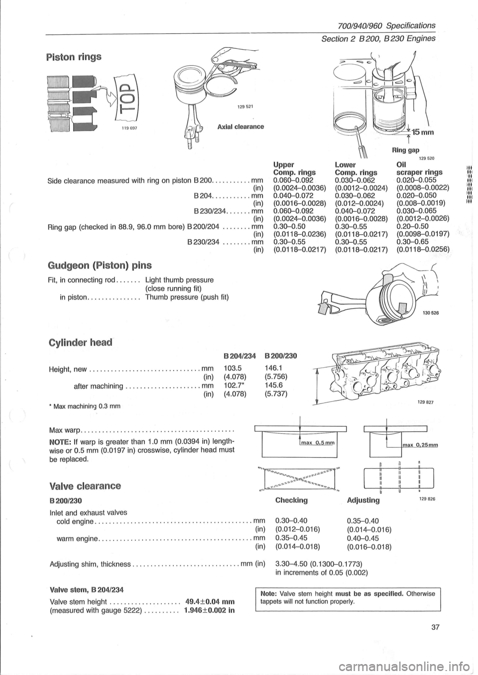
Piston rings
129521
Axial clearance
Side clearance measured with ring on piston 8200 ........... mm
(in)
8204 ........... mm
(in)
8230/234 ....... mm (in)
Ring gap (checked
in 88.9, 96.0 mm bore) 8200/204 ........ mm (in) 8230/234 ........ mm
Gudgeon (Piston) pins
Fit, in connecting rod. . . . . .. Light thumb pressure
(close running fit) (in)
in piston.
. . . . . . . . . . . . .. Thumb pressure (push fit)
Cylinder head-
Height, new ............................... mm
(in)
after machining
..................... mm
(in)
• Max machining 0.3 mm
B204/234
103.5
(4.078)
102.7*
(4.078)
Max warp .......................................... .
NOTE: If warp is greater than 1.0 mm (0.0394 in) length
wise or 0.5 mm (0.0197 in) crosswise, cylinder head must
be replaced.
Valve clearance
B200/230
Inlet and exhaust valves
cold
engine ............................................ mm
(in)
warm engine
........................................... mm
(in)
70019401960 Specifications
Section 2 B 200, B 230 Engines
Upp er Compo rings 0.060-0.092
(0.0024-0.0036)
0.040-0.072 (0.0016-0.0028)
0.060-0.092 (0.0024-0.0036)
0.30-0.50
(0.0118--0.0236)
0.30-0.55
(0.0118--0.0217)
B200/230
146.1
(5.756)
145.6
(5.737)
Checking
0.30-0.40 (0.012-0.Q16)
0.35--0.45 (0.014-0.018)
Lower Compo rings 0.030-0.062 (0.0012-0.0024)
0.030-0.062 (0.012-0.0024)
0.040-0.072 (0.0016-0.0028)
0 .30-0.55
(0.0118--0.0217)
0.30-0.55
(0.0118--0.0217)
Adjusting
0.35--0.40
(0.014-0.016)
0.40-0.45 (0.016-0.018)
Ring gap 129520 Oil scraper rings 0.020-0.055
(0.0008--0.0022)
0.020-0.050 (0.008--0.0019)
0.030-0.065 (0.0012-0.0026)
0.20-0.50 (0.0098--0.0197)
0.30-0.65 (0.0118--0.0256)
max o 25mm
129 826
Adjusting shim, thickness .............................. mm (in) 3.30-4.50 (0.1300-0.1773)
in increments of 0.05 (0.002)
Valve stem, B 204/234
Valve stem height . . . . . . . . . . . . . . . . . . .. 49.4±0.04 mm
(measured with gauge 5222) . . . . . . . . .. 1.946±0.002 in
Note: Valve stem height must be as specified. Otherwise
tappets will not function properly.
37
III III
ill III ill
IN liN
t·
Page 44 of 168
70019401960 Specifications
Section 2 B 200, B 230 Engines
8204/234
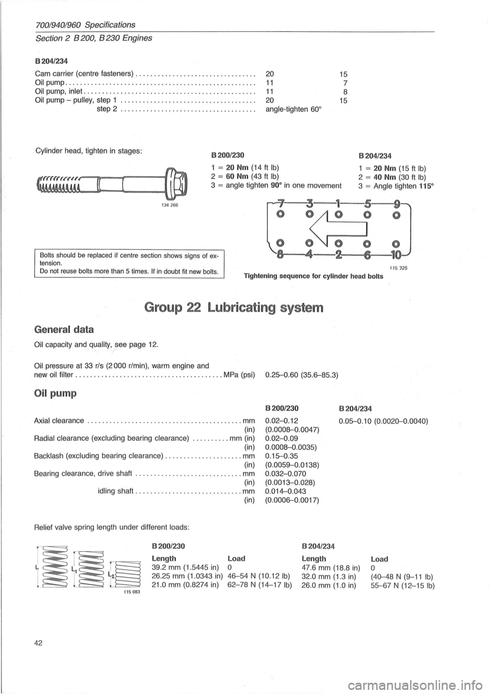
Cam carrier (centre fasteners) . . . . . . . . . . . . . . . . . . . . . . . . . . . . . . . . . 20 15
Oil pump. . . . . . . . . . . . . . . . . . . . . . . . . . . . . . . . . . . . . . . . . . . . . . . . . . . . 11 7
Oil pump, inlet ..... , . . . . . . . . . . . . . . . . . . . . . . . . . . . . . . . . . . . . . . . . . 11 8
Oil pump -pulley, step 1 ..................................... 20 15
step 2 .......... . . . . . . . . . . . . . . . . . . . . . . . . . . . angle-tighten 60 °
Cylinder head , tighten in stages : 8200/230
1 = 20 Nm (14 ft Ib)
2 = 60 Nm (43 ft Ib)
3 = angle tighten 90° in one movement
8204/234
1 = 20 Nm (15 ft Ib)
2 = 40 Nm (30 ft Ib)
3 = Angle tighten 115°
134 266 ~'--~3---1---5,---w9'~
Bolts should be replaced if centre section shows signs of ex
tension.
o ~O
o O~ 0
-~8,---..... 4-2 6 1
ns 125 Do not reuse bolts more than 5 times . If in doubt fit new bolls . Tightening sequence for cylinder head bolts
Group 22 Lubricating system
General data
Oil capacity and quality, see page 12.
Oil pressure at 33 rls (2000 rim in), warm engine and
new oil
filter ........ ; ............................... MPa (psi) 0.25-0.60 (35.6-85.3)
Oil pump
8200/230
0.02-0. 12
(0.0008-0.0047)
0 .
02-0.09
0.0008-0.0035)
0 .
15-0.35
(0.0059-0.0138)
0 .
032-0.070
(0.0013-0.028)
0 .
014-0.043
(0.0006-0.0017)
8204/234
Axial clearance ................ ... ....................... mm
(in)
Radial clearance (excluding bearing clearance) . ......... mm (in)
(in)
Backlash (excluding bearing clearance) ..................... mm
(in)
Bearing clearance , drive shaft
............................. mm
(in)
idling shaft .................... ......... mm
Relief valve spring length under different loads:
115083
42
8200/230
Length
39.2 mm (1.5445 in)
26.25 mm (1. 0343 in)
21.0 mm (0.8274 in) (in)
Load
o
46-54 N (10.12 Ib)
62-78 N (14-17 Ib)
0.05-0.
10 (0.0020-0.0040)
8204/ 234
Length
47.6 mm (18.8 in)
32.0 mm (1.3 in)
26 .0 mm (1.0 in)
Load
o
(40-48 N (9-11 Ib)
55-67 N (12-15 Ib)
Page 66 of 168
700/940/960 Specifications
Section 2' 8200,8230 Engines
Group 25 Intake and exhaust systems
Turbo engines
'-198~
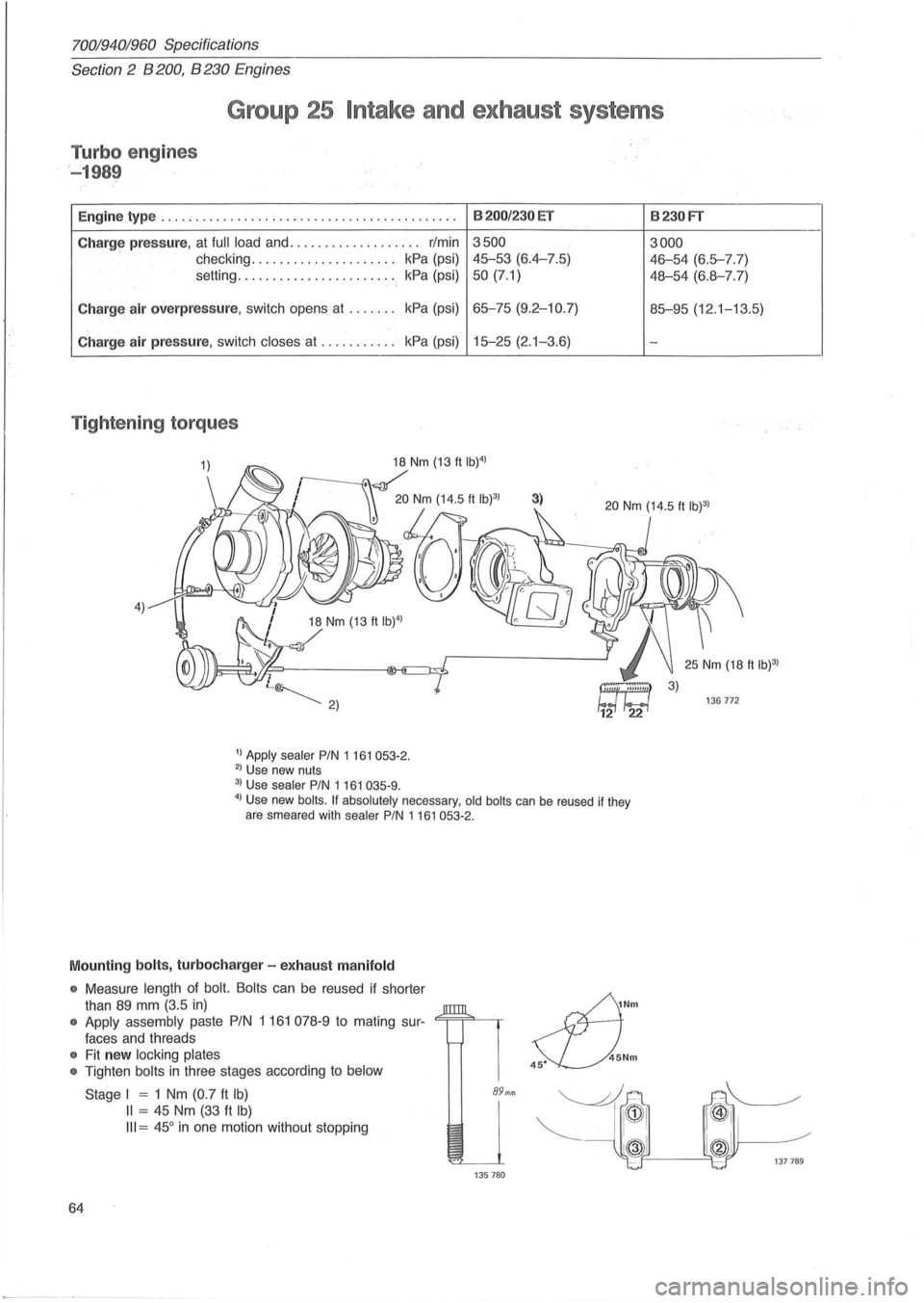
Engine type .... ; ......... . , ............ .. .............
Charg~ pressure, at full load and ................... r/min
checking
.. ................... kPa (psi)
setting. . . . . . . . . . . . . . . . . . . . .
.. kPa (psi)
Charge air overpressure, switch opens at ....... kPa
(psi)
Charge air pressure, switch closes at ........... kPa (psi)
Tightening torques
4) 18 Nm (13 ft IW)
/
1) Apply sealer PIN 1 161 053-2. 2) Use new nuts
3) Use sealer PIN 1161 035-9.
8200/230 ET
3500
45-53 (6.4-7.5)
50 (7.1)
65-75 (9.2-10.7)
15-25 (2. 1-3.6)
3)
4) Use new boils. If absolutely necessary, old boils can be reused if they
are smeared with sealer PIN 1161053-2.
Mounting bolts, turbocharger -exhaust manifold
• Measure length of bolt. Bolts can be reused if shorter
than
89 mm (3.5 in)
• Apply assembly paste PIN 1 161 078-9 to mating sur-<=;==;=""-~
faces and threads
• Fit new locking plates
•
Tighten bolts in three stages according to below
64
Stage I = 1 Nm (0.7 ft Ib)
II = 45 Nm (33 ft Ib)
III = 45° in one motion without stopping
89mm
135780
~Nm
s::L).Nm
8230FT
3000
46-54 (6.5-7.7)
48-54 (6.8-7.7)
85-95 (12 .1-13.5)
-
136772
Page 76 of 168
70019401960 Specifications
Section
2 B 28 Engine
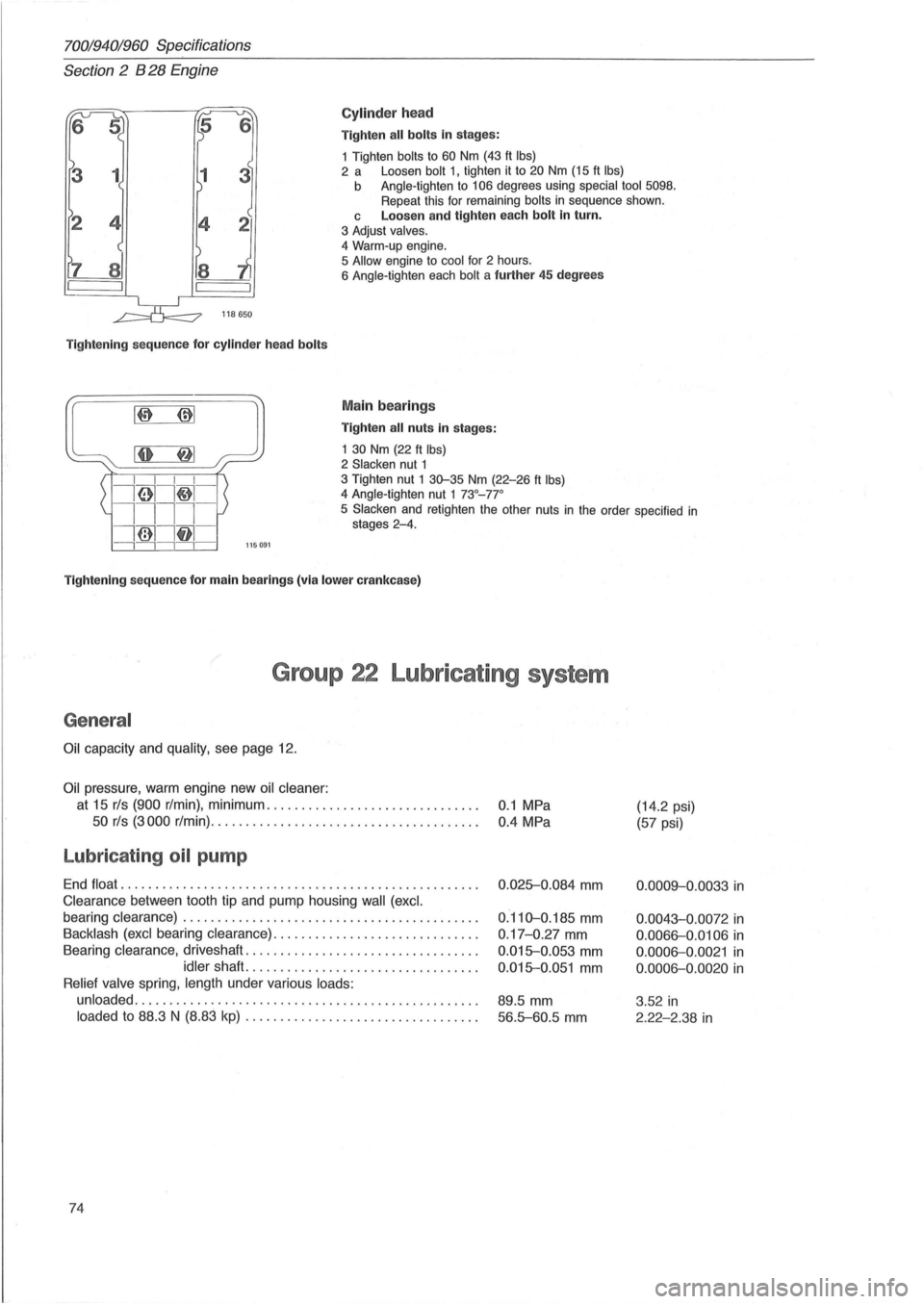
Cylinder head
Tighten all bolts in stages:
1 Tighten
bolts to 60 Nm (43 ft Ibs) 2 a Loosen bolt 1, tighten it to 20 Nm (15 ft Ibs) b Angle-tighten to 106 degrees using special tool 5098. Repeat this for remaining bolts in sequence shown.
118650
Tightening sequence for cylinder head bolts
L~~::~:~' ~I ~: I I I I
i61I~-
c Loosen and tighten each bolt in turn.
3 Adjust valves.
4
Warm-up engine.
5 Allow engine to cool for 2 hours.
6 Angle-tighten each bolt a further 45 degrees
Main bearings
Tighten all nuts in stages:
1
30 Nm (22 ft Ibs) 2 Slacken nut 1 3 Tighten nut 1 30-35 Nm (22-26 ft Ibs) 4 Angle-tighten nut 1 73°_77 °
1111-
i@1lf11 -
5 Slacken and retighten the other nuts in the order specified in stages 2-4.
---,---,---,---,-115091
Tightening sequence for main bearings (via lower crankcase)
Group 22 Lubricating system
General
Oil capacity and quality, see page 12.
Oil pressure, warm engine new oil cleaner:
at 15 rls (900 r/min), minimum .............................. .
50 rls (3000 r/min) .......... ....... ......... ............ .
Lubricating oil pump
End float ................................................... .
Clearance between tooth tip and pump housing wall (excl.
bearing clearance) .......................................... .
Backlash (excl bearing clearance) ................ ............. .
Bearing
clearance, driveshaft ................................. .
idler shaft. ................................ .
Relief valve spring, length under various loads:
unloaded
................................................. .
loaded to 88.3 N (8.83 kp) ............ ... .... .............. .
74
0.1 MPa
0.4 MPa
0 .
025-0.084 mm
0.110-0.185 mm
0 .17-0.27 mm
0.015-0.053 mm
0.015-0.051 mm
89.5 mm
56.5-60.5 mm
(14.2 psi)
(57 psi)
0.0009-0.0033 in
0.0043-0.0072 in
0.0066-0.0106 in
0 .0006-0.0021 in
0.0006-0.0020 in
3 .52 in
2.22-2.38 in
Page 94 of 168
70019401960 Specifications
Section 2 B 280 Engine
Group 22 Lubricating system
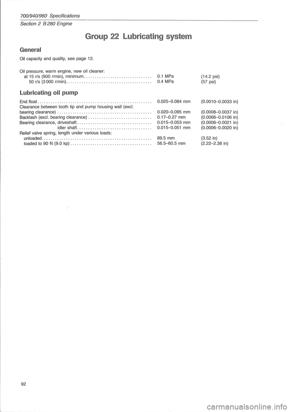
General
Oil capacity and quality, see page 12.
Oil pressure, warm engine , new oil cleaner:
at 15 rls (900 r/min), minimum. . . . . . . . . . . . . . . . . . . . . . . . . . . . . . . 0.1 MPa
50 rls (3000 r/min). . . . . . . . . . . . . . . . . . . . . . . . . . . . . . . . . . . . . . . 0.4 MPa
Lubricating oil pump
End float ...... ........................ ..................... .
Clearance between tooth tip and pump housing wall (excl.
bearing clearance) .
......................................... .
Backlash (excl. bearing clearance) ............................ .
Bearing clearance , driveshaft ....
............................. .
idler shaft ................................. .
Relief valve spring, length under various loads:
unloaded
..................... ................. ........... .
loaded to 90 N (9.0 kp) .................................... .
92
0.025-0.084 mm
0.020-0.095 mm
0.17 -0.27 mm
0.015-0.053 mm
0.015-0.051 mm
89.5 mm
56.5-60.5 mm
(14.2 psi)
(57 psi)
(0.0010-0 .0033 in)
(0.0008-0 .0037 in)
(0.0066-0 .0106 in)
(0.0006-0 .0021 in)
(0.0006-0.0020 in)
(3.52 in)
(2.22-2.38 in)